Project 1
1. Create Civil 3D Design File.
2. Create surface File & Create Surface by using given Survey Data.
3. Create Alignment by Using Proper Geometry Standard & apply Supeelevation.
4.Create View frames & sheet & create seperate .dst file for the same.
5. Workout quantity by using civil 3d.
1. Create Civil 3D Design File.
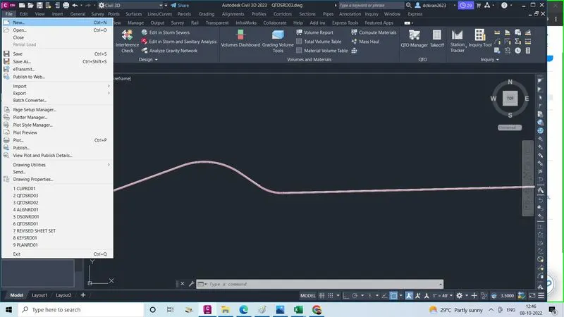
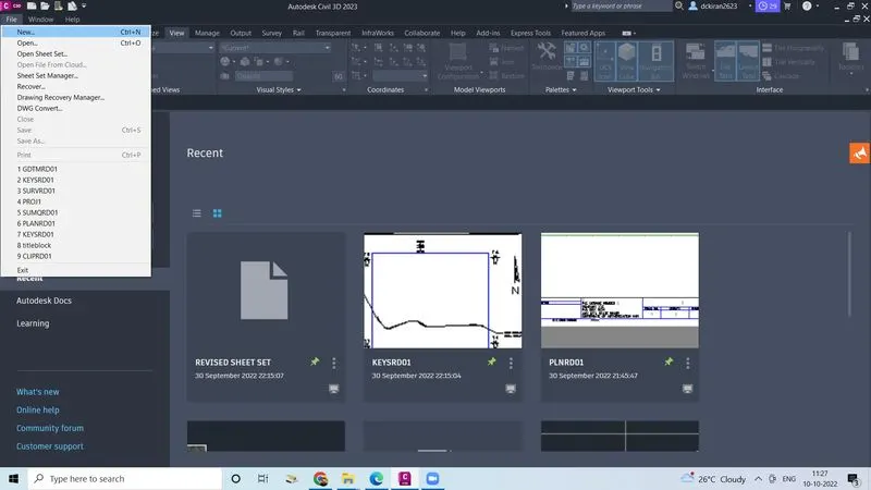
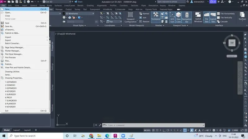
- Go to file
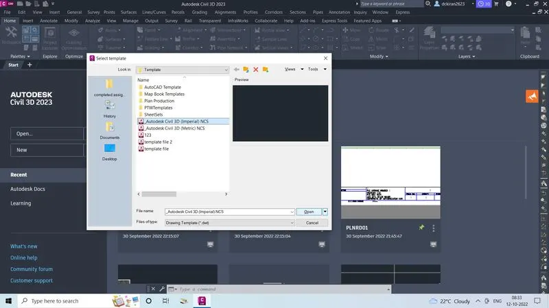
- Click on the new
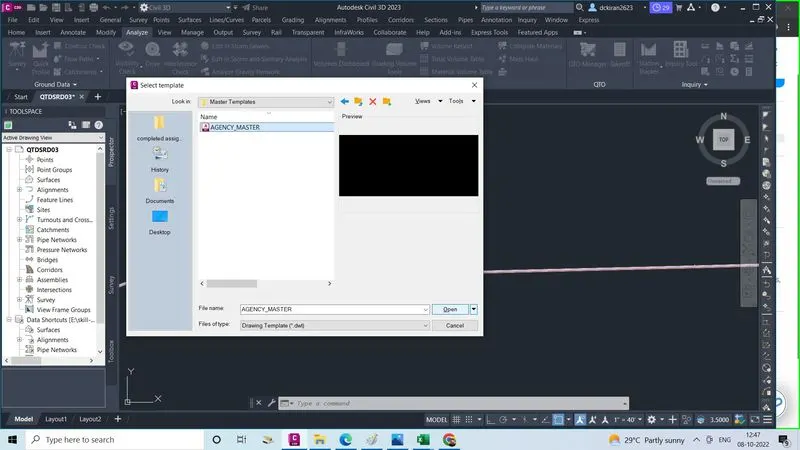
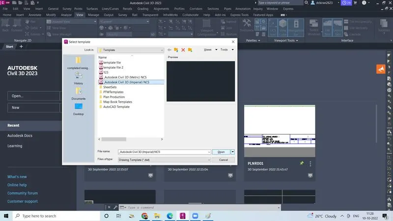
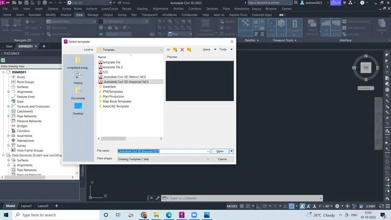
- Select one template file ( imperial,metric) as in the civll 3d
- Click open
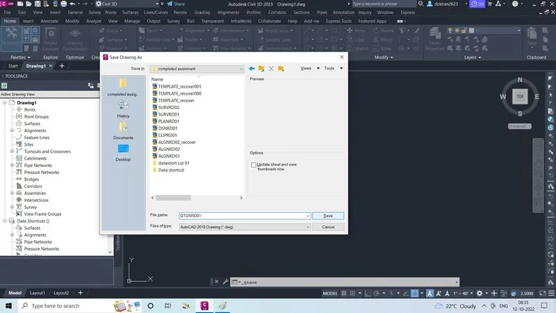
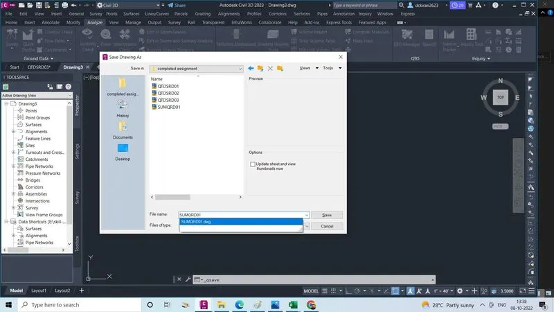
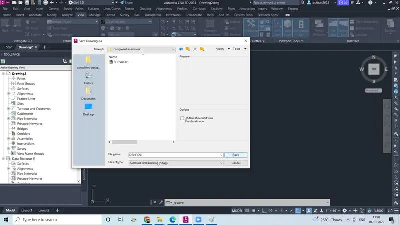
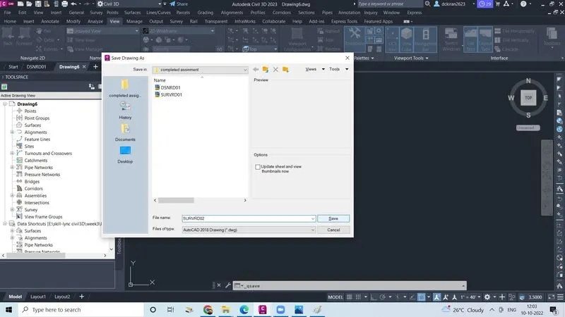
- Type command CTRL+S saving file will open in that give name as DSNRD01 as .dwg form and save in the proper folder ( Skill-lync civil 3d/project 1/completed assignment)
- Click on the save
- Now design file created
2. Create surface File & Create Surface by using given Survey Data.
- Go to file
- Click on the new template file (imperial or metric)as in the civil 3d
- Click open
- Type command CTRL+S to save
- Give a name as (SURVRD) as .dwg form save in the proper folder ( skill-lync civil3d/ project/completed assignment )
- Click on the save
- Now surface file is created
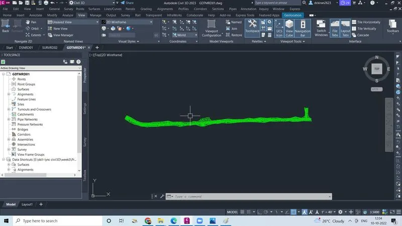
- Open the survey data (GDTMRD01) file which is provided by the company
- Copy all the survey data from GDTMRD01 file
- Go in the SURVRD file
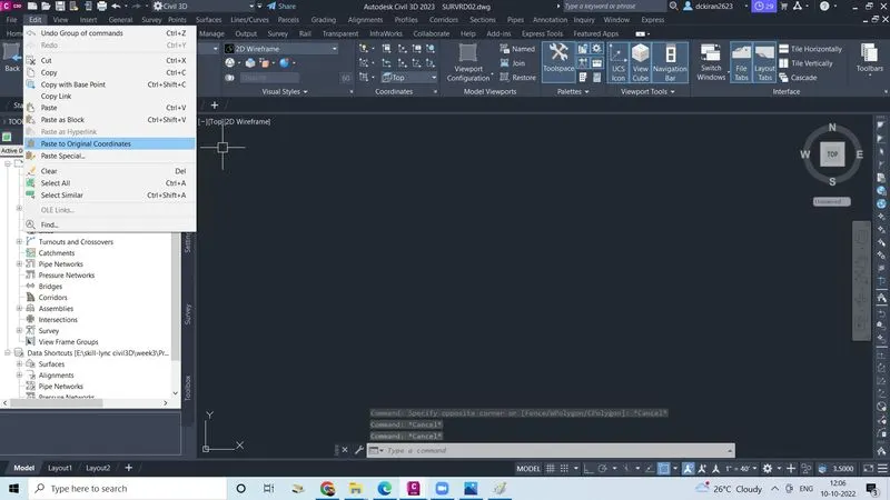
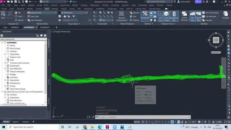
- Click on the paste to original co-ordinates
- ZE enter
- Now in (SURVRD)file toolspace/prospectror
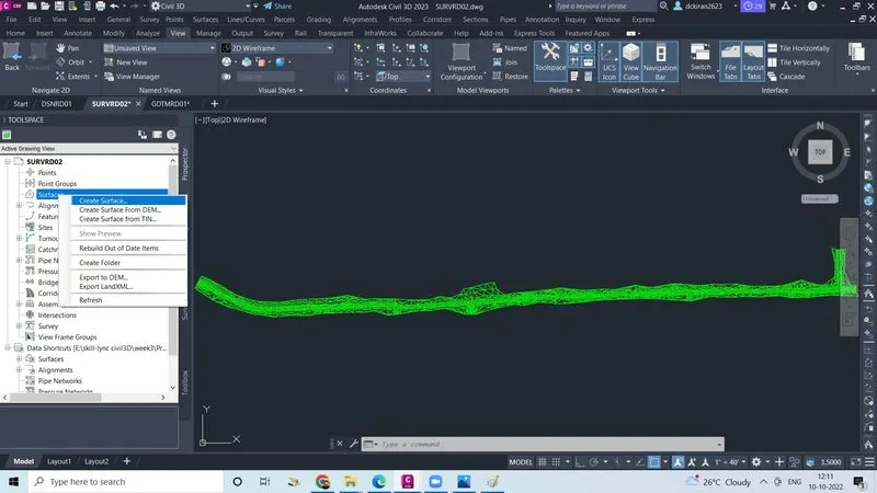
- Select the surface and righg click on the surface
- Click on the create surface
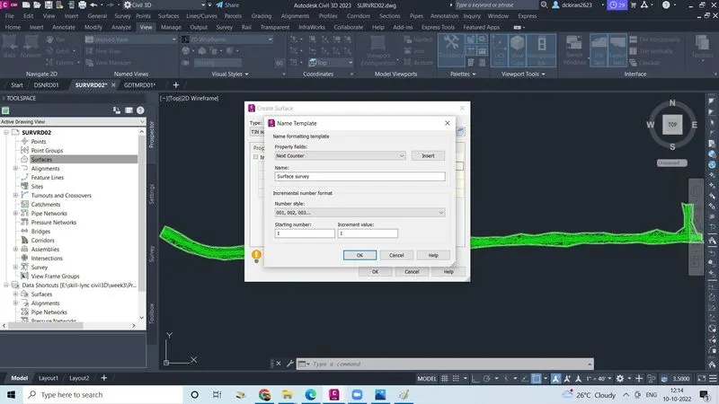
- One sheet will open, in the give name and discription
- Click ok
- Now surface is created
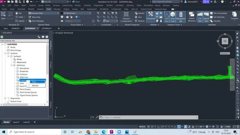
- Now click on surface /definition
- Select drawing objects and right click
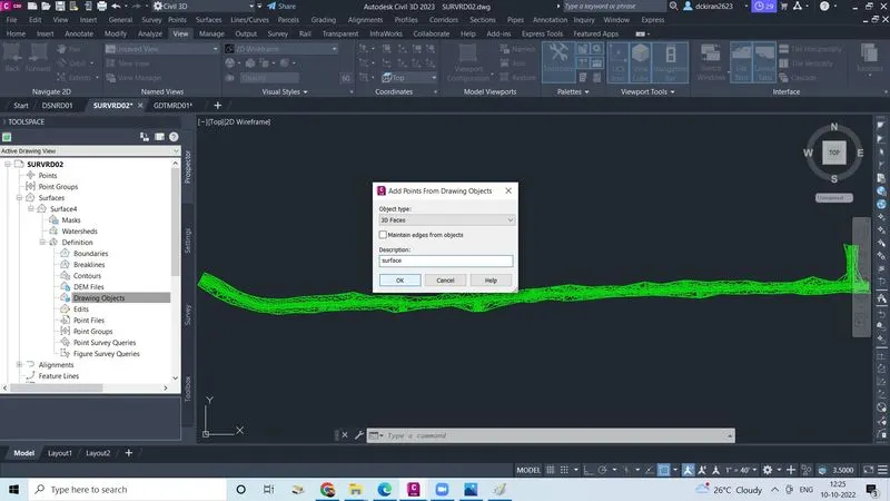
- Click add, select object type as 3d faces description as surface
- Click ok, it shows select the object
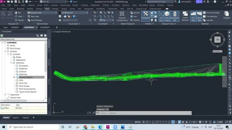
- Then select the object click enter
- Now surface is created using survey data
3. Create Alignment by Using Proper Geometry Standard & apply Supeelevation.
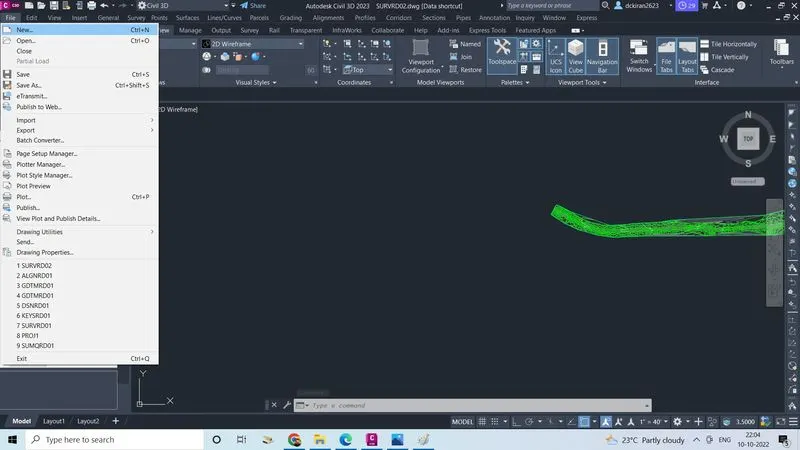
- Go to file
- Click on new
- Select one template file ( imperial, or metric)
- Click open
- Type command CTRL+S one file will open
- Give a name as (ALGNRD01) as ,dwg form
- Save in a proper folder (skill lync civil 3d/ project1/ completed assignment)
- Click on save
- Alignment file is created (ALGNRD)
- Open (GDTMRD) survey data file in the civil 3D file
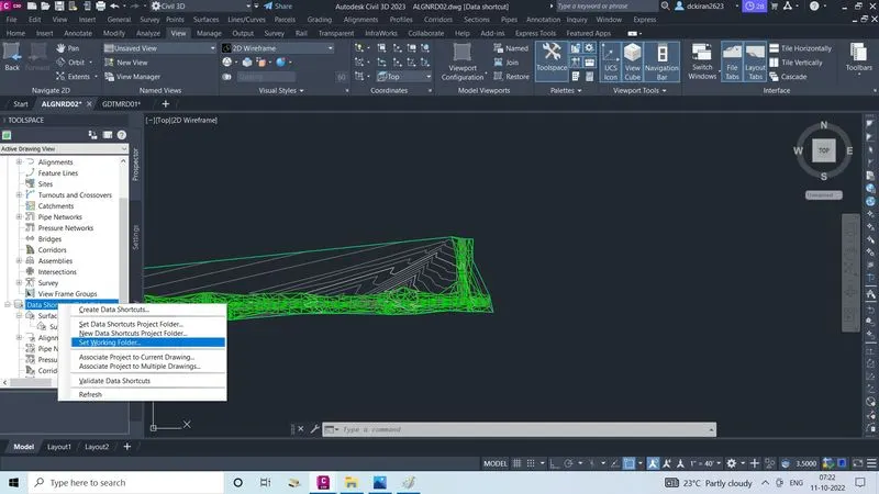
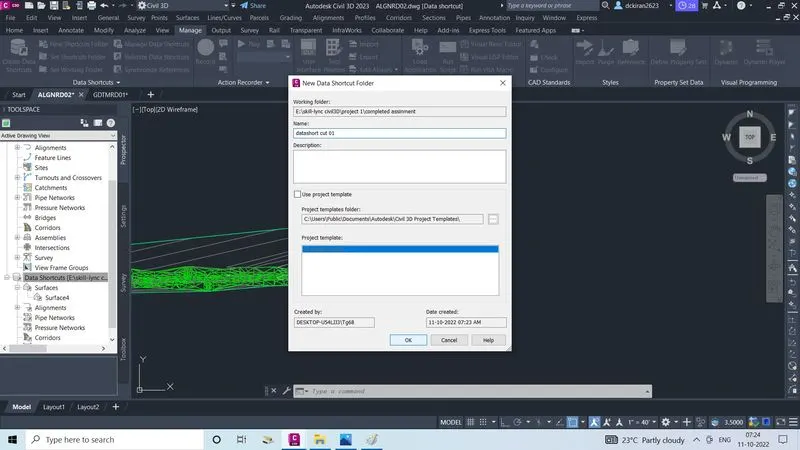
- Create data shortut in alignment file(ALGNRD)
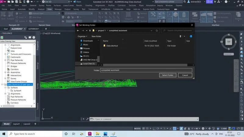
- Go to manage
- Click on the set working folder first ,select the folder as a completed assignment
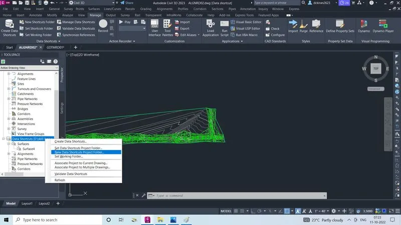
- After click on the new new short cut,created folder exist there
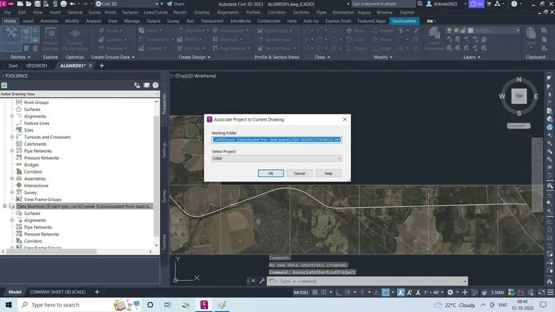
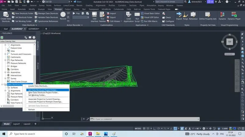
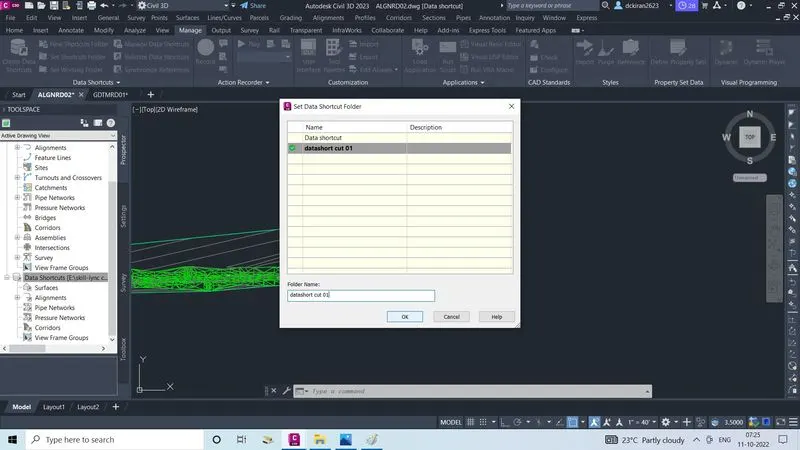
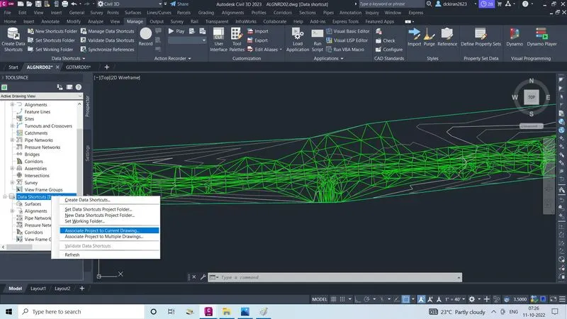
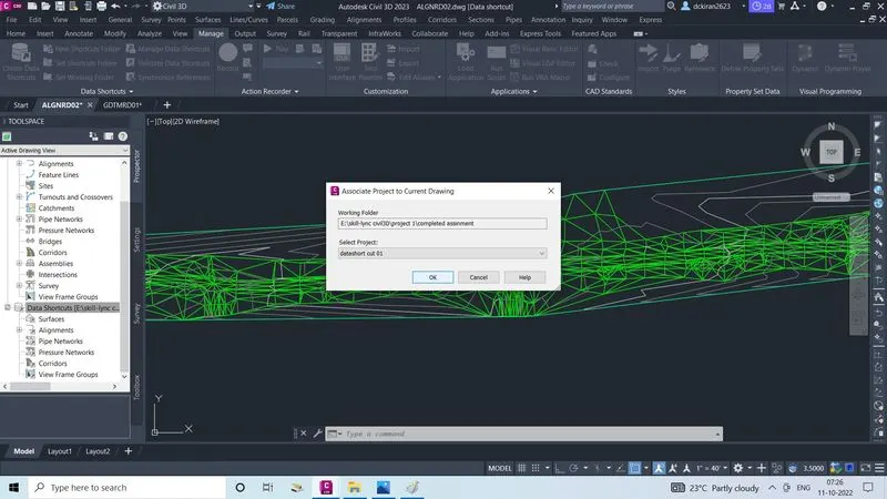
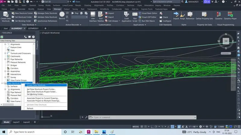
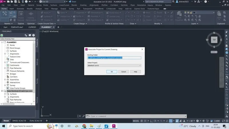
- Select and right click on data shortcut ,click on associate to current drawing
- Select the project and click ok
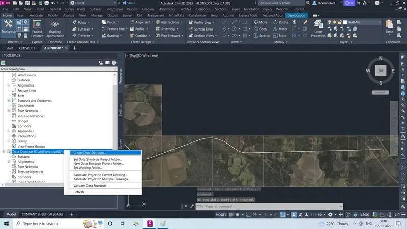
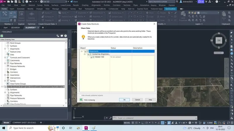
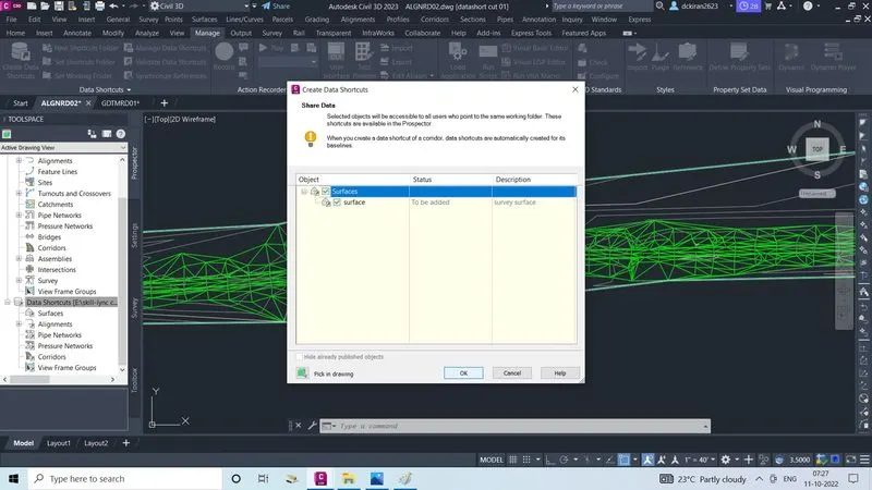
- Lastly right click on data shortcut click on creat data shortcut, select the object and click ok
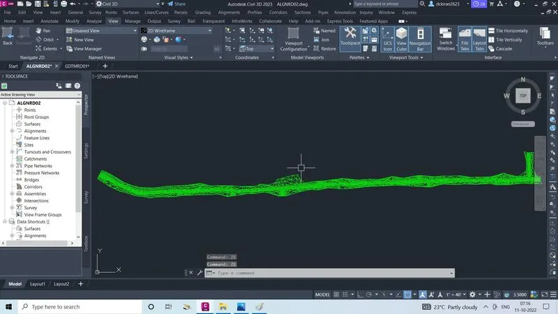
- Now data shortcut is created,copy the survey data from (GDTMRD) file
- Go to (ALGNRD) file, go to edit, click on paste to original coordinates
- ZE enter
- Select the surface and right click on create surface
- Give name and description
- Click ok
- Now surface is created
- Click on the surface /definition/select drawing object and right click
- Click on add, select the object type as 3D faces and click
- Select the object and click ok
- Now surface and counter is reflacted
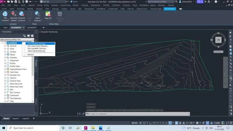
- Go to ALGNRD tool space/setting
- Right click on the (ALGNRD) click on edit drawing setting
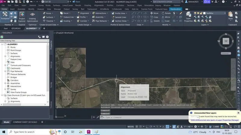
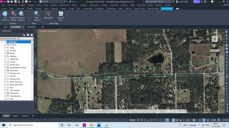
- Add the geo-location as FL83-NF to turn on geo-location in order to check wheater it is in the correct location or not and draw the alignment perfectly
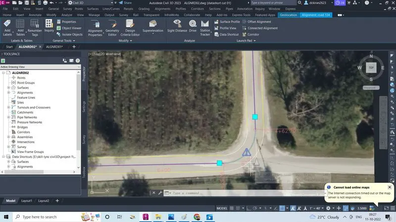
- Now start drawing the alignment
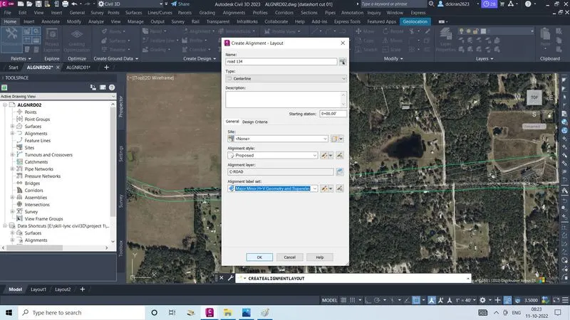
- Go to home click on alignment, create alignment layout will open
- Give the alignment name as Road-134, we can set alignment label set,click ok
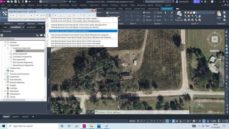
- Click on tangent-tangent no curve to draw alignment
- Click on the free sprial-curve -sprial(b/w two entites) to draw the curve b/w the two entites
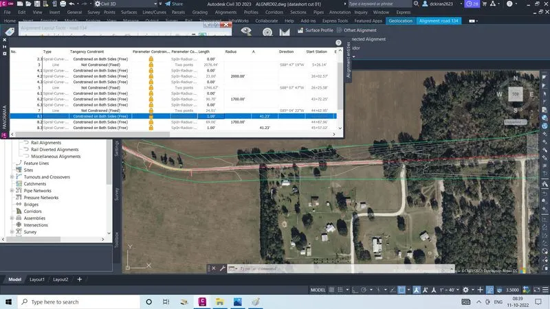
- Select the first entites then second entites then enter the radius, lenght now curve is setted
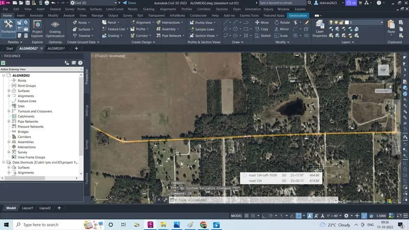
- Alignment is drawn
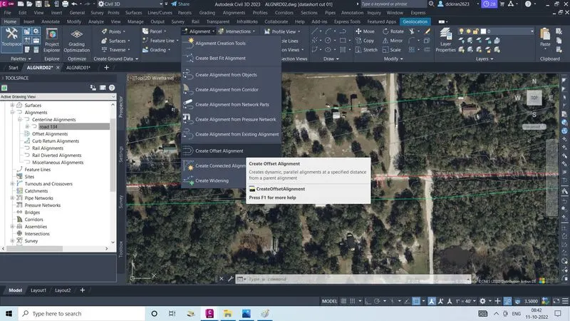
- Now go to alignment click on create offset alignment to draw offset of the alignment
- Select to alignment one dailog box will activate
- Enter the offset of the alignment and click ok
- Or else we can increase the no of offset or we can do change the alignment style
- Now we have to apply super elevation
- Superelevation is represanted by E and its formula E=V2/225R (v) speed and (R) radius are the parameters of superelevation
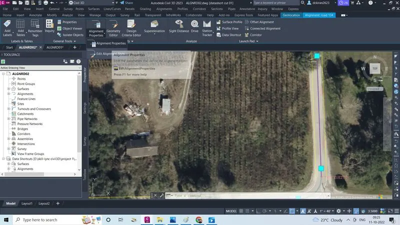
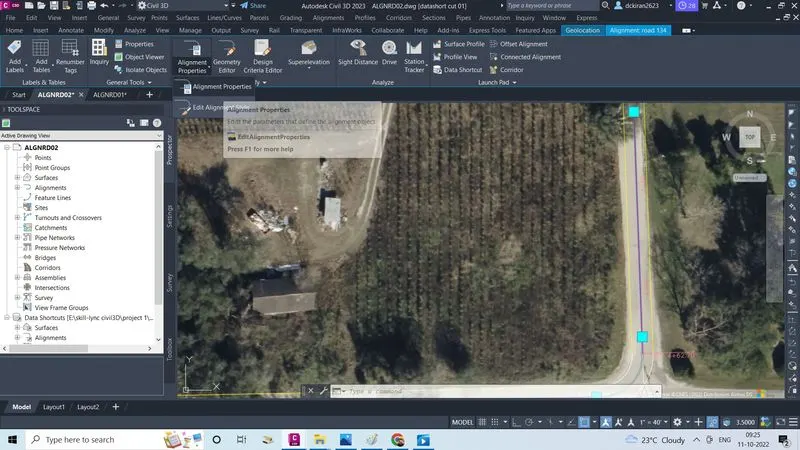
- Select the alignment, dailog box will get activated
- Now go to alignment properties click on that again click on sub alignment properties option
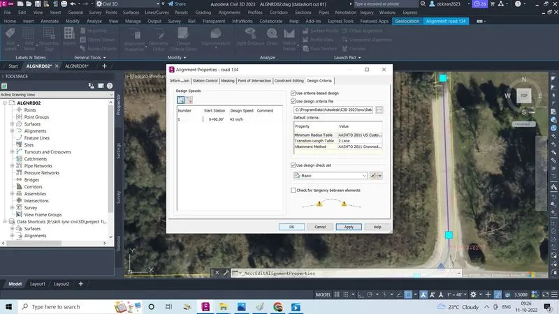
- Again one dailog box will open
- Click on design criteria, check mark on use criteria-based design,and uncheck on check for tangency b/w elements
- Set the speed as 45m/h and click apply and ok
- Now speed ia assigned to a entire alignment
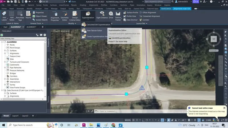
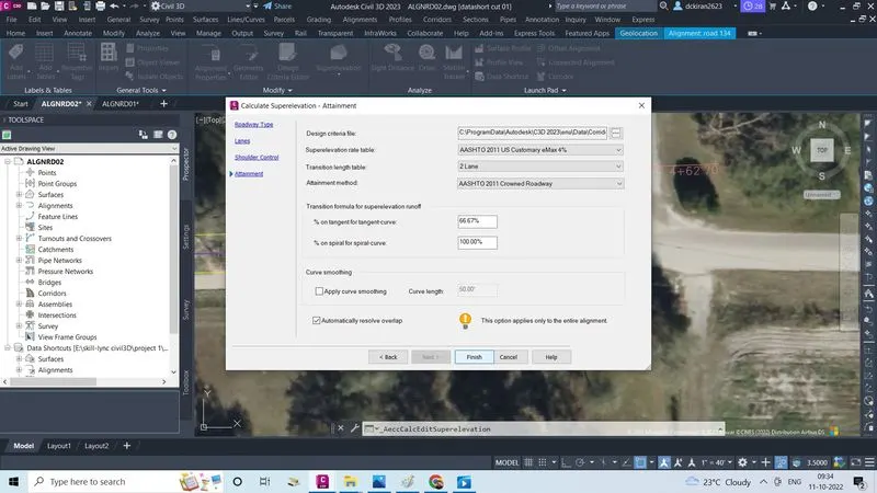
- Now click on the superelevation , click on the caluclate/edit superelevation
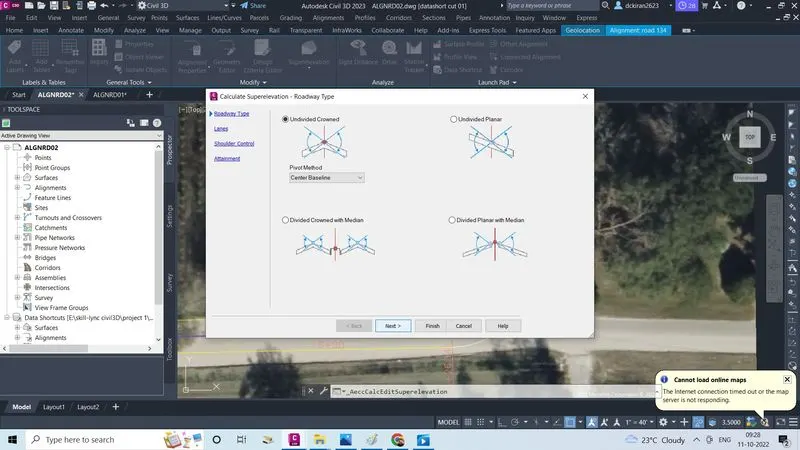
- Select undivided crownes, click next
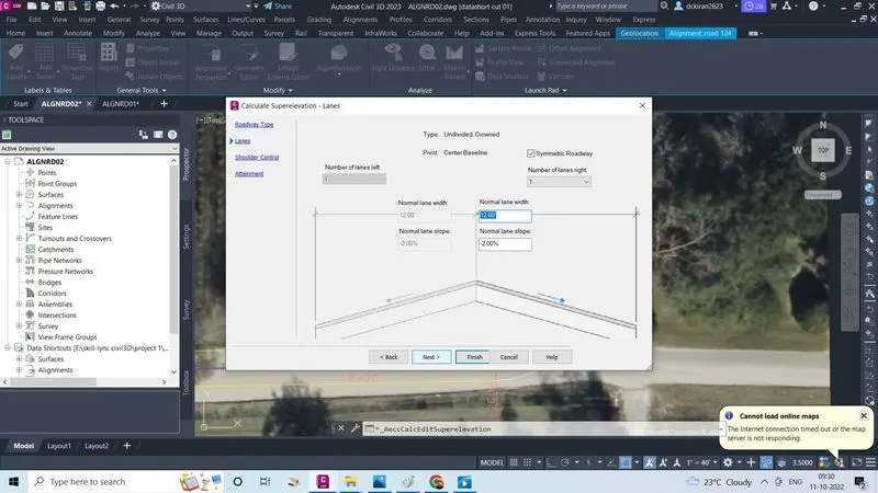
- select the symetric, so no of canes on left and right is same
- Give the normal lane width is 12 and normal lane slope is -2%, click next
- As our typical selection our sholder with is 6' give width is 6'and normal sholder slope is -6%, click next
- Now check mark on the automaticaly resolve over lap
- and Click finish
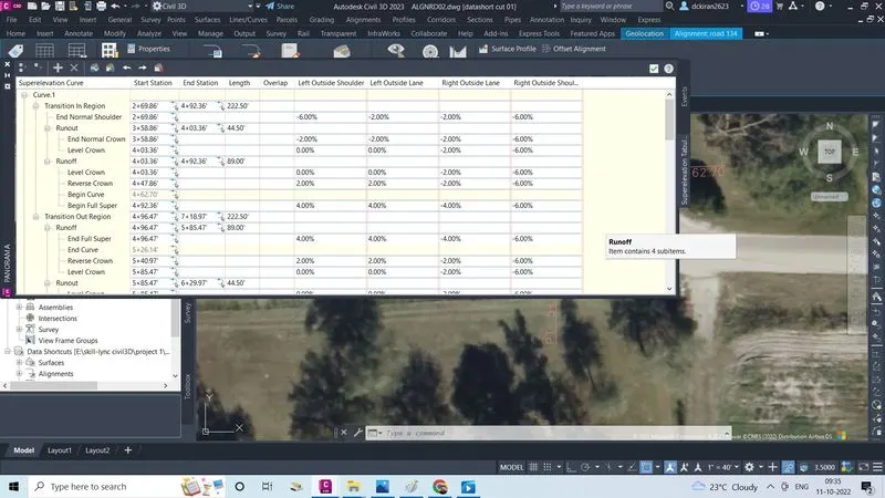
- Now super elevation also applied to the alignment
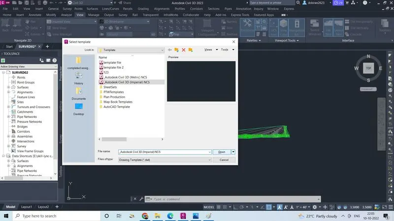
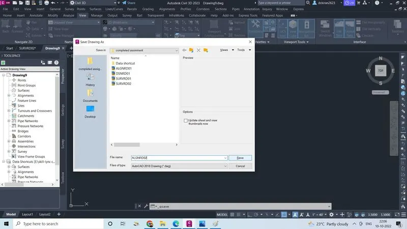
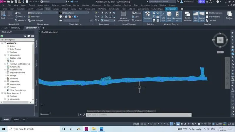
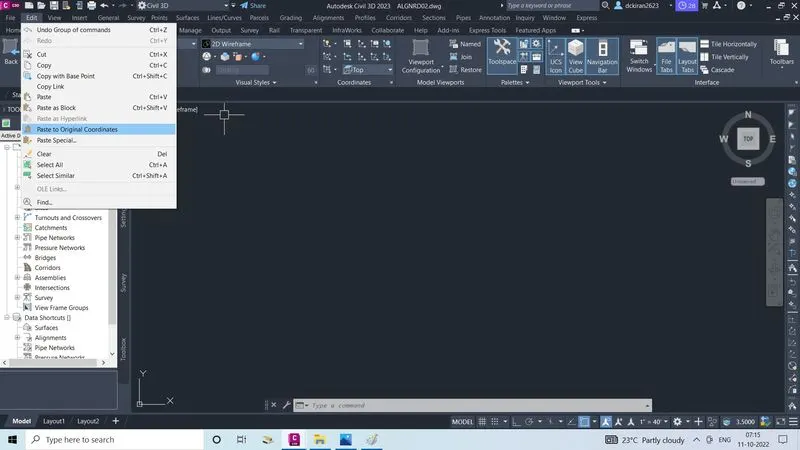
4.Create View frames & sheet & create seperate .dst file for the same.
- To create view frame first we have to create template file, .DST file, CLIPRD file, then after view frame sheets is created in PLANRD file so
- First click on file
- Click on new
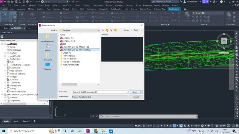
- Select one template file (imperial or metric )
- Click open
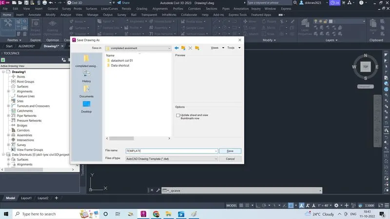
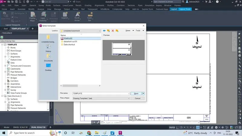
- Type command CTRL+S and give name as TEMPLATE in .dwt form save in a proper folder (skill lync civil3d/project 1/completed assignment )
- click on save
- Type command CTRL+4 sheet set manger will open
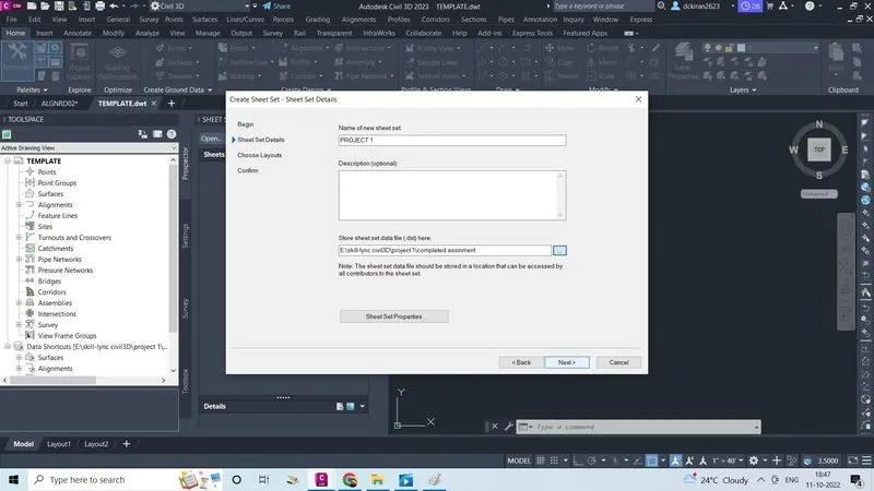
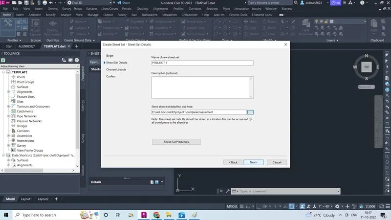
- Click on new sheet set, click on either (sheet set or existing drawing )and click next
- And give new sheet set name as PROJECT 1 and that .dst file will store in (Skill lync civil3d/project 1/completed assignment) click next,next
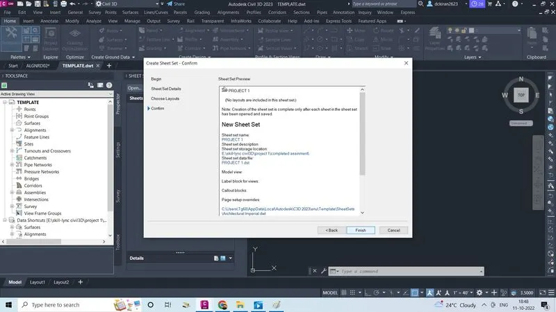
- In confirm option sheet set preview will see click finish
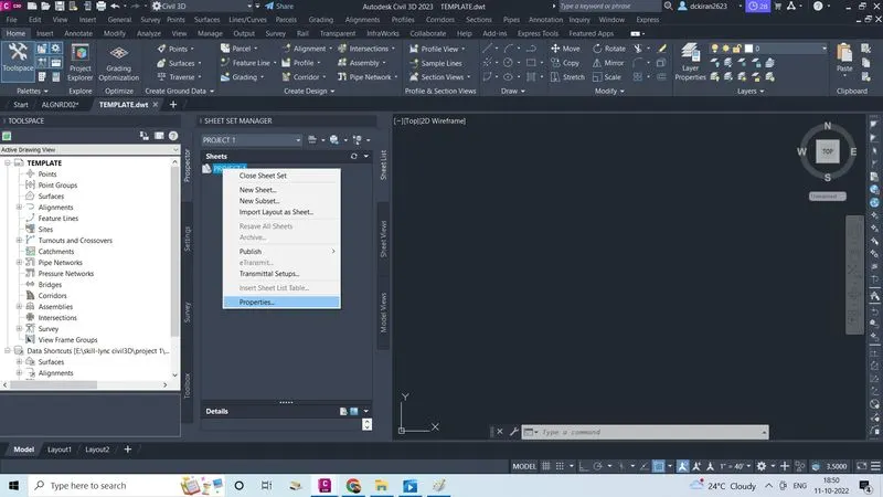
- Select and right click on the created new sheet set
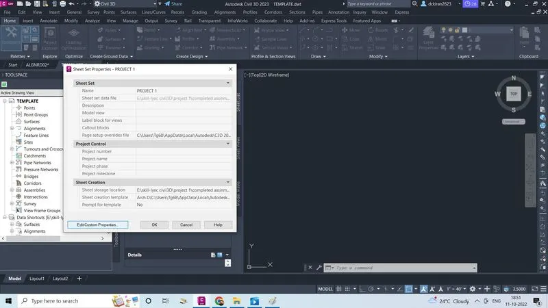
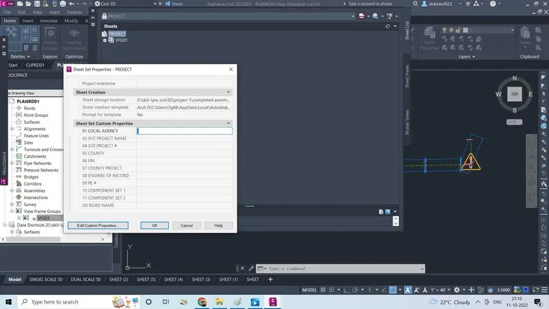
- Click on the properties,project 1 properties will open
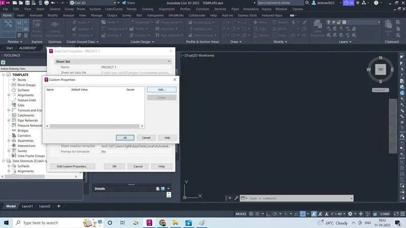
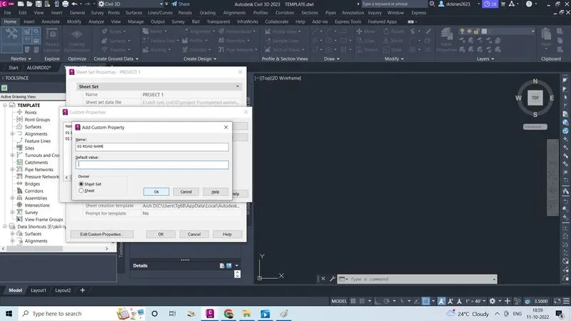
- Click on edit custom properties
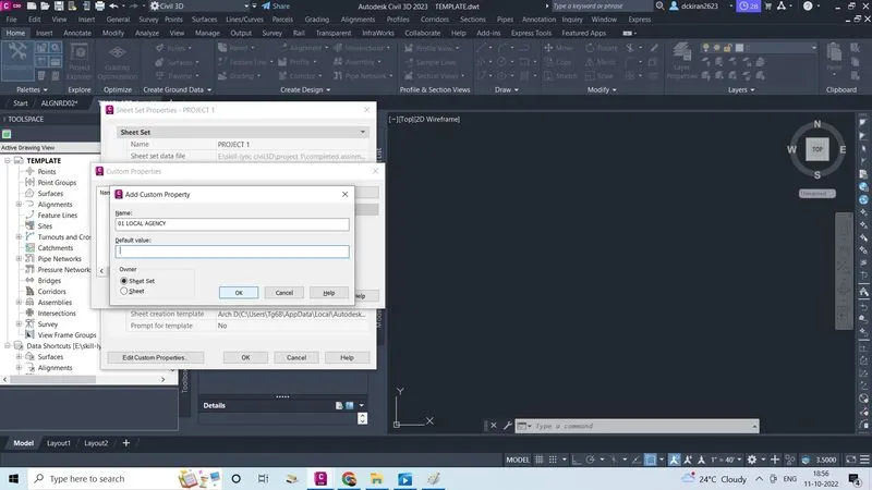
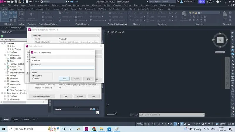
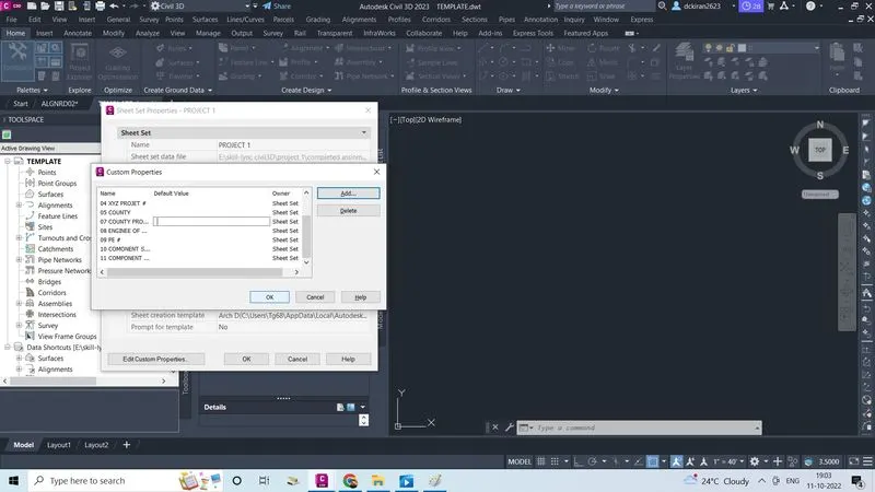
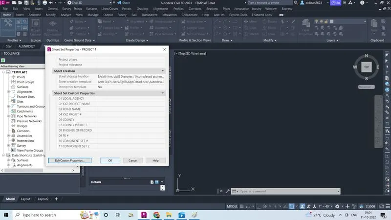
- There we have to add the custom properties like 01 LOCAL AGENCY, 02 PROJECT NAME ,03 ROAD NAME #, 04 XYZ PROJECT #,05 COUNTY, 06 FIN ,07 COUNTY PROJECT,08 ENGINEE OF RECORD, 09 PE#10COMPONENT SET 1, 11 COMPONENT SET 2
- First give the name as o1 LOCAL AGENCY
- Give defualt value as ATL+0160
- Click ok
- Do the same procedure for all custome properties
- Last click ok,ok
- Now we have to set layout sheet
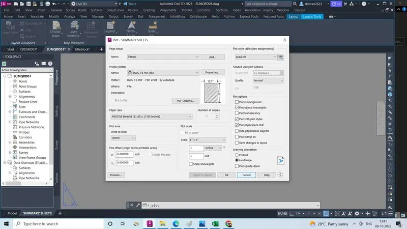
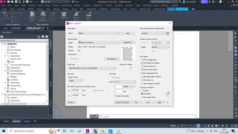
- CTRL+P, plot will open give name as DWG to PDF, paper size id Ansi full bleed B(11*17 inches) plot style table as acad.ctb
- Click on apply to layout and cancle
- Now we have to open titleblock in the civil3D which is provided by the company
- Copy that titleblock and paste in the template file in layout sheet, with a proper center of paper sheet
- We have to create single scal 50' as well as dual scale 50'layout
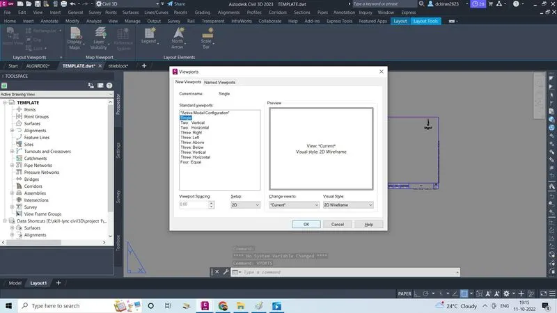
- Type command VPORTS select first single
- Click ok
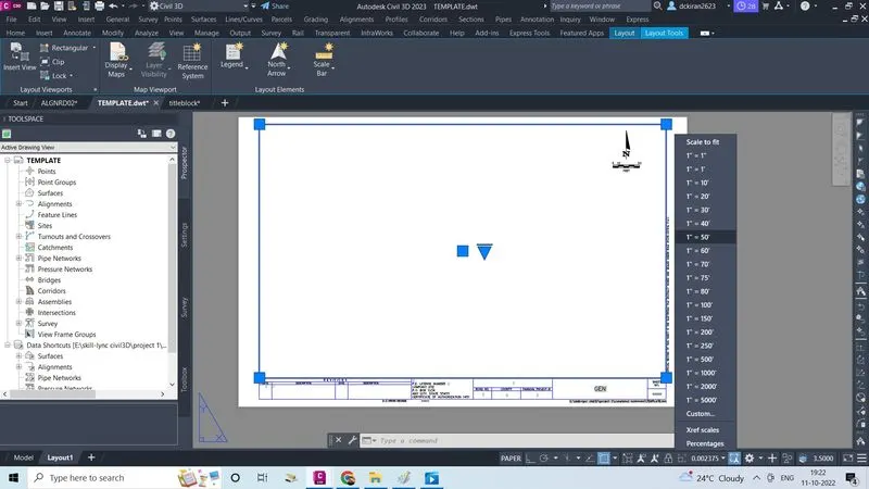
- Set the scale as 1"=50' and lock it
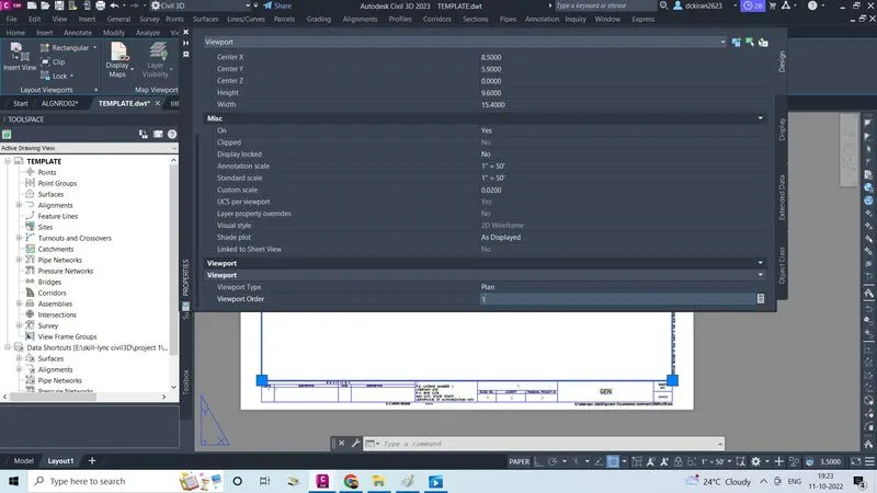
- Type command properties in viewport select view type as plan and view order is 1 as do the same procedure to create dual plan scale 50'
- Now we have to create new file called CLIPRD
- Go to file
- Click on new
- Select one template file which we created now as (TEMPLATE) it is in the skill lync civil3d/project/completed assignment
- Click open
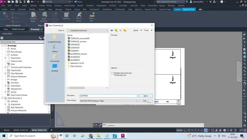
- Type command CTRL+S give name as (CLIPRD01) as .dwg form store in the proper folder
- Click on save
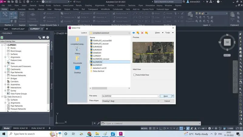
- To create view frame we required alignment file id required and already data shortcut is created in the alignment file (ALGNRD)
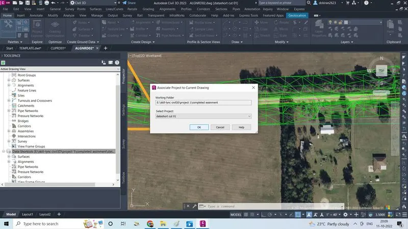
- In Alignment file (ALGNRD) right click on the data shortcut select the project as datashort o1
- Click ok
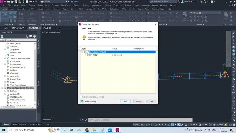
- Right click on data shortcut, click on create data shortcut
- Select the object ,click ok
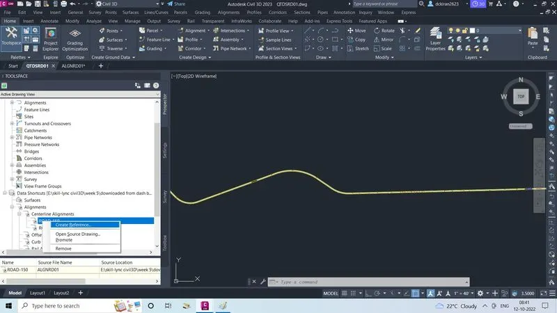
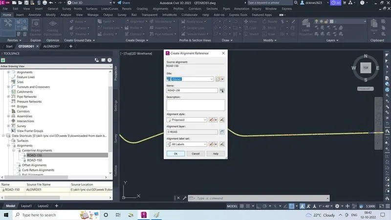
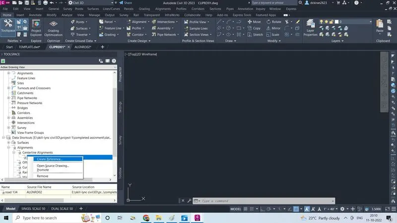
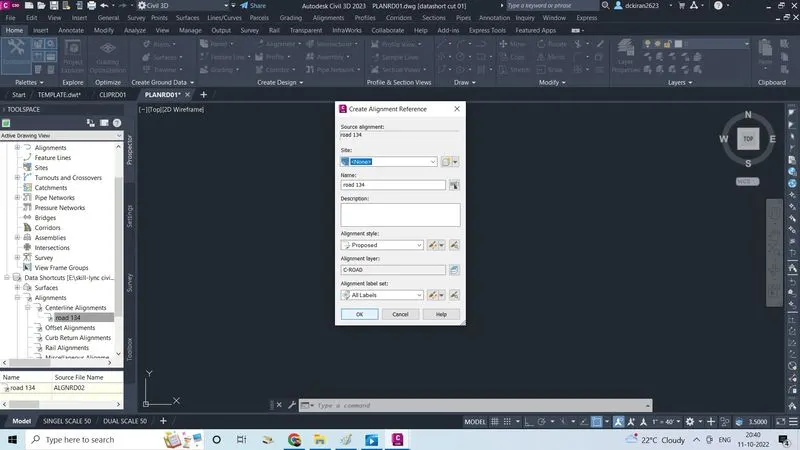
- In (CLIPRD01) file data shortcut/alignment/center alignment/road 134 right click
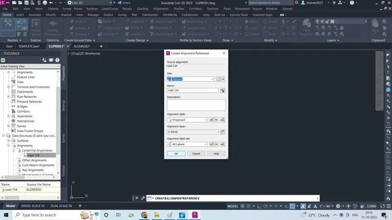
- Click on create reference
- Click ok
- In (CLIPRD01) prospector/view frame groups
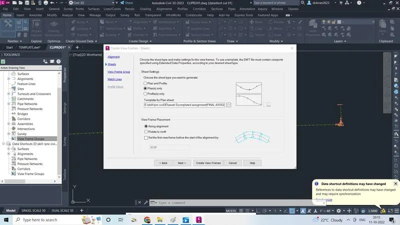
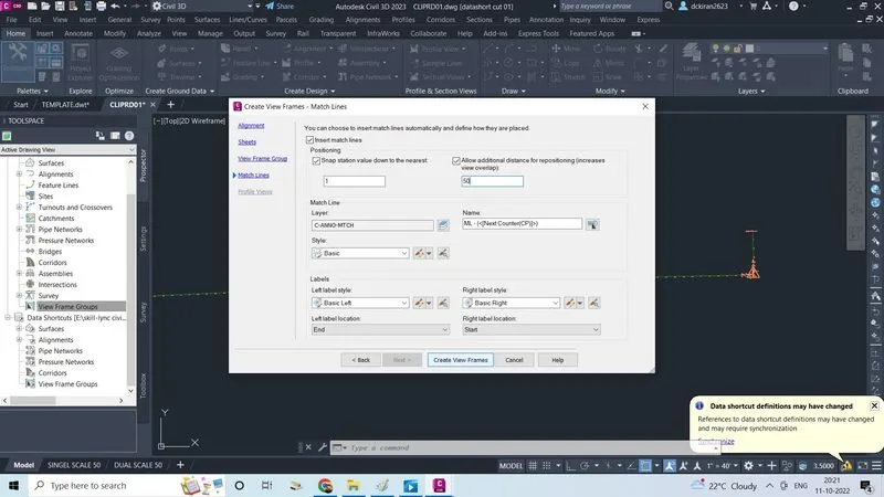
- Right click on view frame groups ,click on create view frames
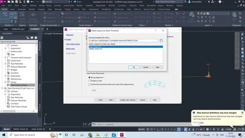
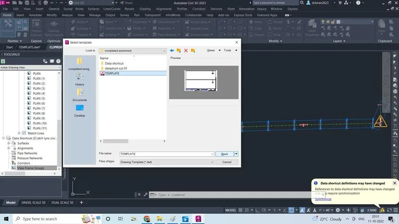
- Select the template folder, select the dual scale 50',click ok
- In view frame groups give name as VFG01
- Click next
- Check marke on the auditional distanec for responition increase view overlap give 50
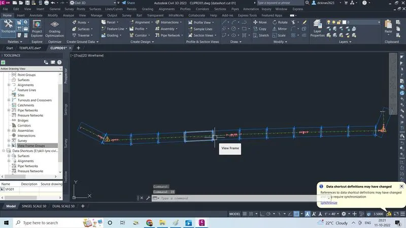
- Click on create view frame
- View frame is created in CLIPRD file
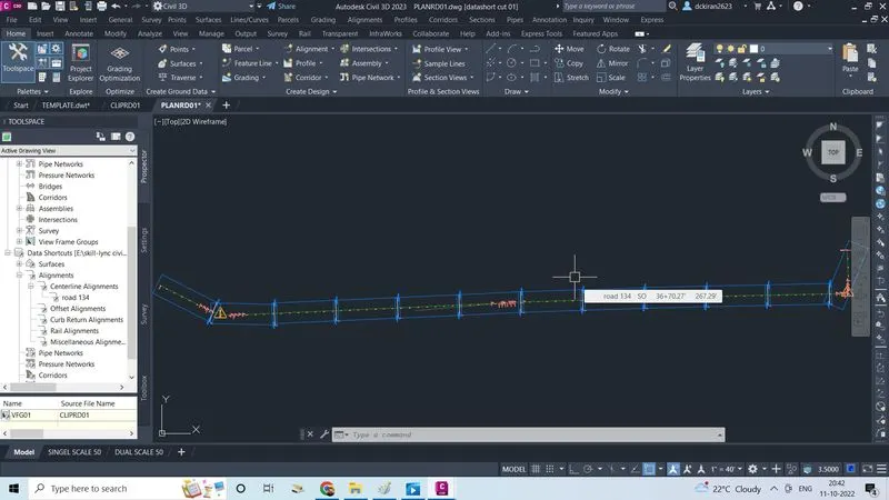
- View frame sheet are actualy shown in (PLANRD)
- Click on new
- Select a template file (TEMPLATE ) which is in (skill lync civil3d/project 1 /completed assignment )
- Click open
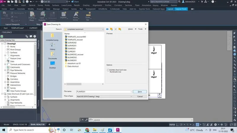
- Type command CTRL+S give name (PLANRD01) store in a proper folder
- Click on save
- In CLIPRD01 right click on the data shortcut, click on associate to current drawing select project , click ok
- Right click on CLIPRD01 click on create data short ,select the object ,click ok
- In PLANRD01 data shortcut/ alignment/center alignment/road 134 right click ,click on create reference ,click ok
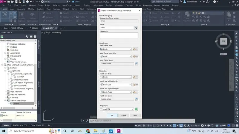
- Lastly right click on the view frame
- Click create reference
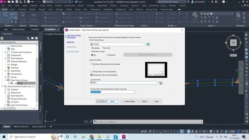
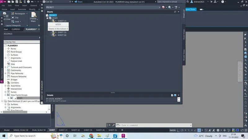
- Right click on the created view frames click on the create sheets
- Check mark on the all layouts in the current drawing
- Give layout name as SHEET click next
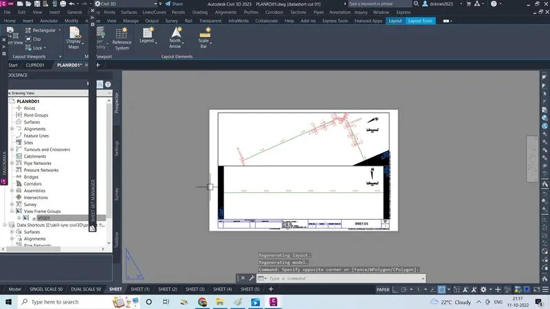
- View frame alignment sheet are created
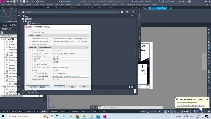
- Select all the right click on the project, click on properties
- Give the discription for the sheet set costum properties as provided by the company click ok
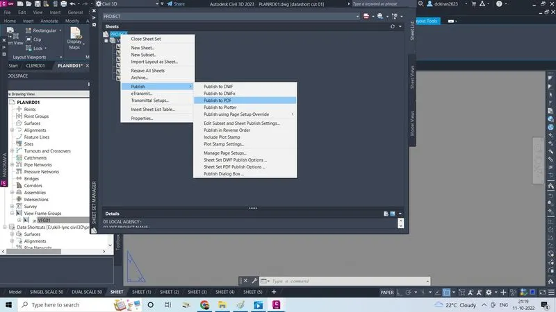
- Select and right click on the project, click on publish to pdf
5. Workout quantity by using civil 3d.
- Go to file
- Click on the new
- Select a template file as (imperialpr metric) as given the civil 3D
- And click open
- Save this file by typing command CTRL+S
- Give a name as QTDSRD in .dwg form
- Click on the save
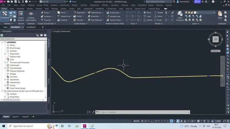
- After creating a quantity file (QTDSRD) file
- Insert DSGNRD file which is provided by the company its in the (skill lync/project 1/downloaded from dash board/CADD/roadway)
- And copy that by CTRL+C
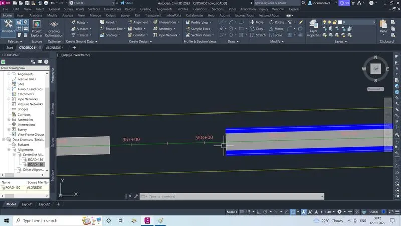
- Paste in the QTDSRD file by clicking on edit click on paste to original co-ordinates
- After copying the DSGNRD file into a QTDSRD file
- Lets open alignment file (ALGNRD) file in the civil3D
- And copy the alignement from (ALGNRD) file
- And paste in the (QTDSRD) file by going on edit option , click on the paste to original coordinates
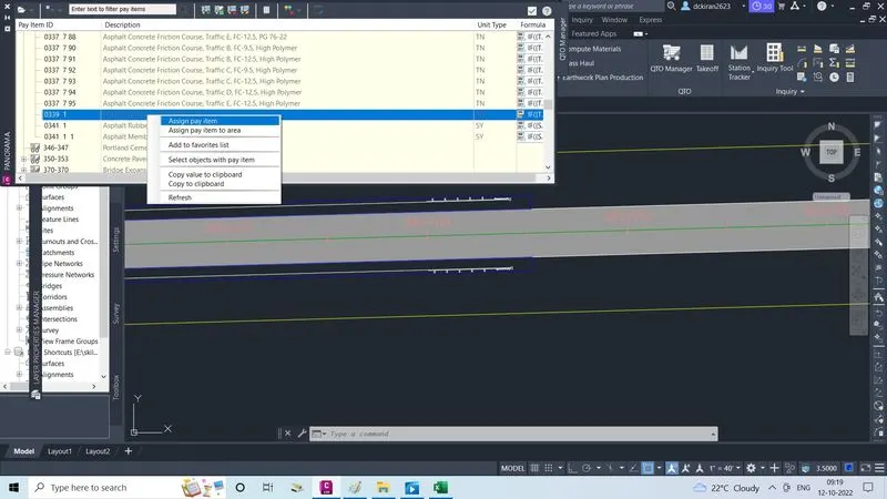
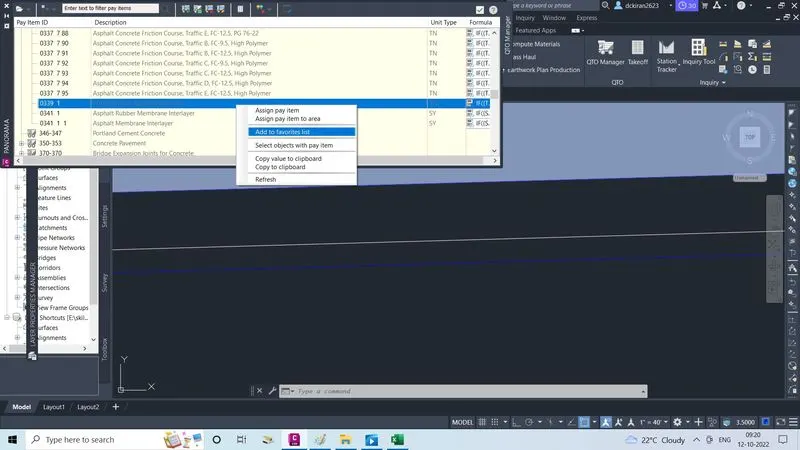
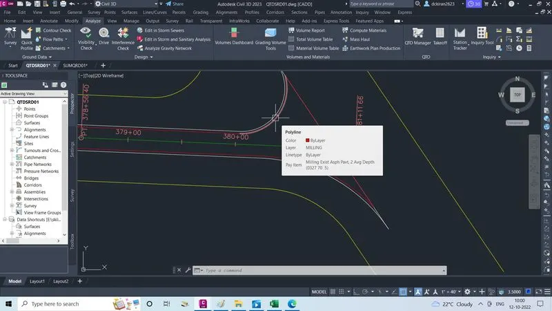
- Now we have to fix pay items by assigning the quantites
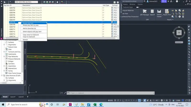
- Go to analysis, click on the QTO manager
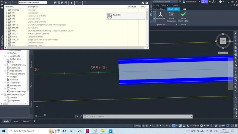
- Then PANORAMA sheet will open, click on file in the panorama sheet
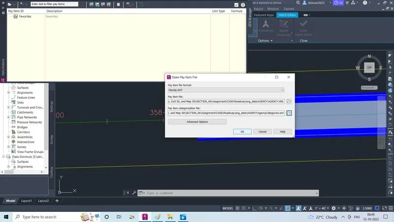
- Click on open pay item file
- Pay items file will open, in that select the formate as Florida to select the pay items
- As agency, which is provided by the company & select pay items categorization as agency categories which is provided by the company
- Click on ok
- After fixing all pay items
- Now we have to assign the quantity, which company iis said to assign the following quantity like a) Guardrial (053610 & 05368524) b) lump sump [mobilization{01011},maintanence of trafic{010211}c) misc asphalt{03391}d) pavement (type B stabilization,optional base,base group 08,milling exist asph pavt,2"avg dept ,superpave ASPHALITC conc traffic Be) turf f) turnouts
- First we assign the guardrial as per the company provided
- First we will check the item ID (number) of gurdrail
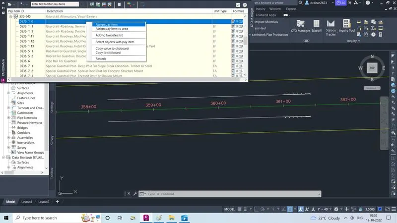
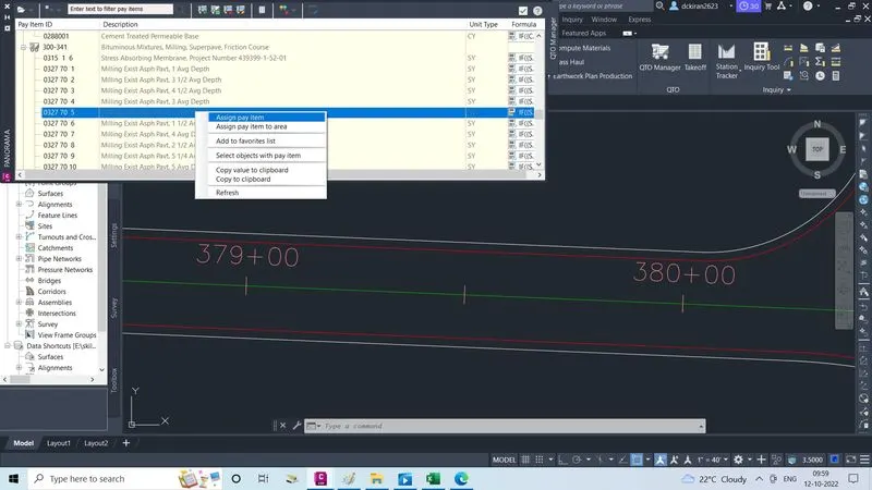
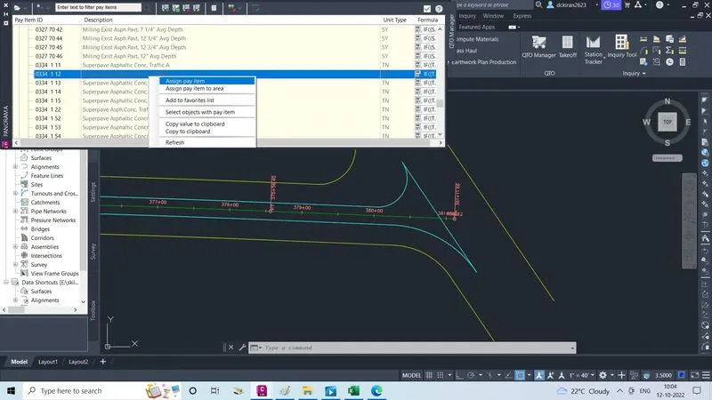
- Select the guardrial roadway general/low speed It -2 right click on that click on the assign pay item
- Select the objects click enter
- Like wise select guardrial end treatment parallel approach terminal right click on that, select the those objects & clcik enter
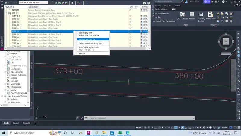
- After assigning select & right click on both
- Now lump-sump (mobilization,maintance of traffic ) for this there is no any quantity to assign , so we will add this un a percentage
- Now misc asphalt
- Do the same procedure by seeing the typical section diagram there they gave how much we have to do for asphalt
- Know the item no of asphalt
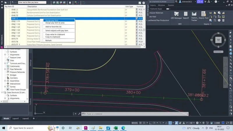
- Select miscellaneouss asphalt pavement right click on that
- Click on assign pay item to area, because it is a untis area so we selected that
- Select the objects & click enter
- Like wise do the same for all
- After assigining all the quantities
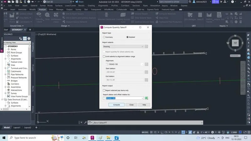
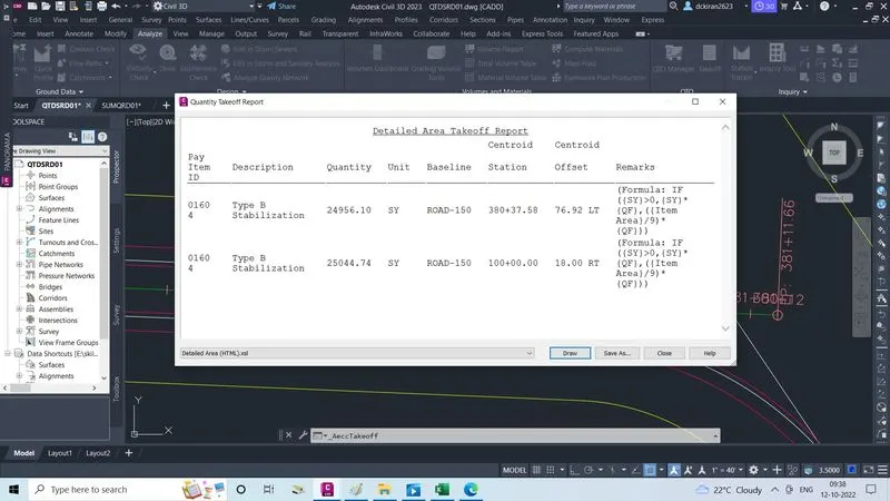
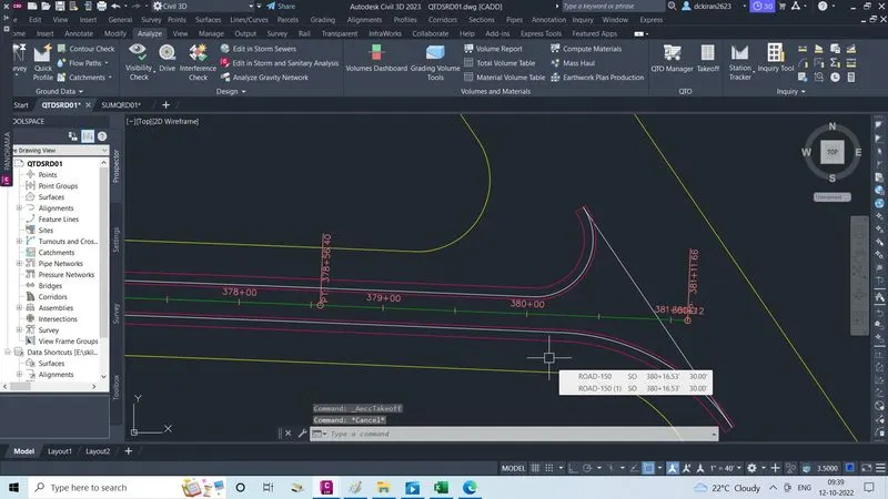
- Go to take off & click on that
- One fill will open
- Select report type summary or detailed
- Select report extents as drawing
- Select station & offset relative to as road-150
- Click on compute
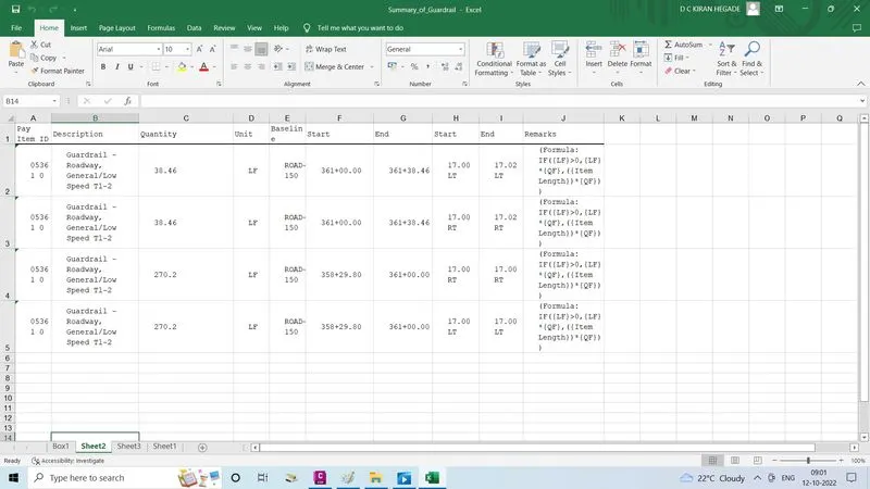
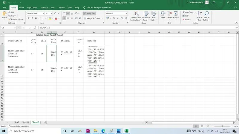
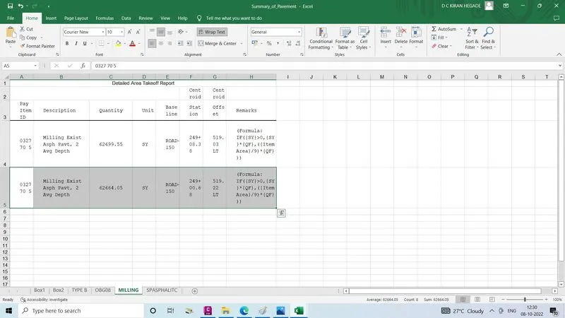
- Quantity takeoff report will open
- Select the file type
- Copy those thing & paste in the excel sheet with a respect folder or click on the save as
- Now create new file called (SUMQRD)
- Go to file, click new, select one template file & click open
- Type command CTRL+S give name SUMQRD save itin the particular folder skill-lync/project 1/completed assignment
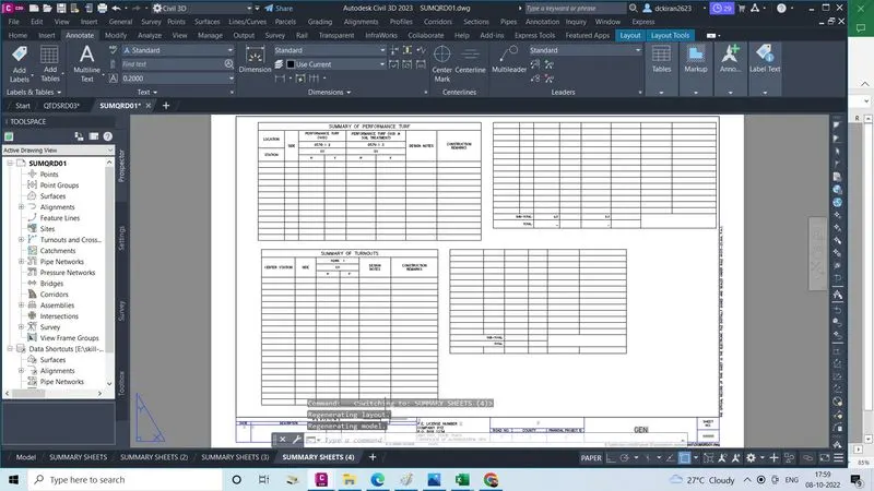
- Create a layout sheet by open in the title block into a civil3d ,& do all the procedure to be a correct size
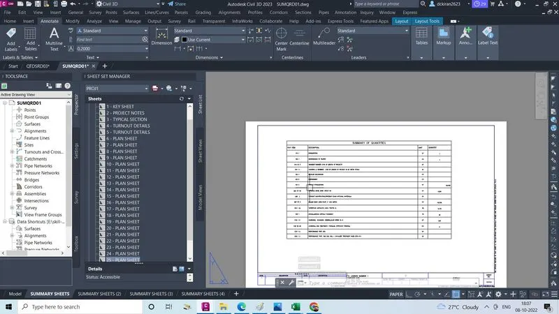
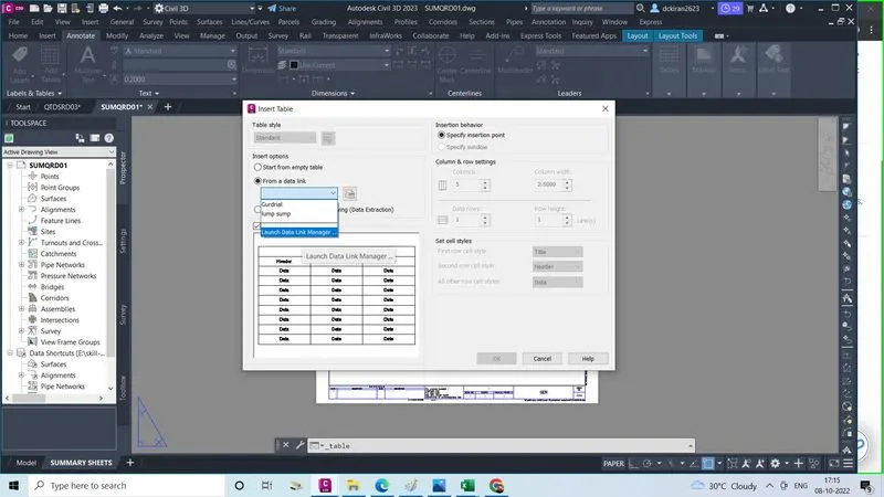
- Now go to annotate option ,in ribben, click on the table option, and click sub table option
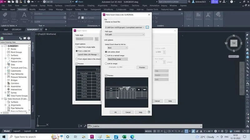
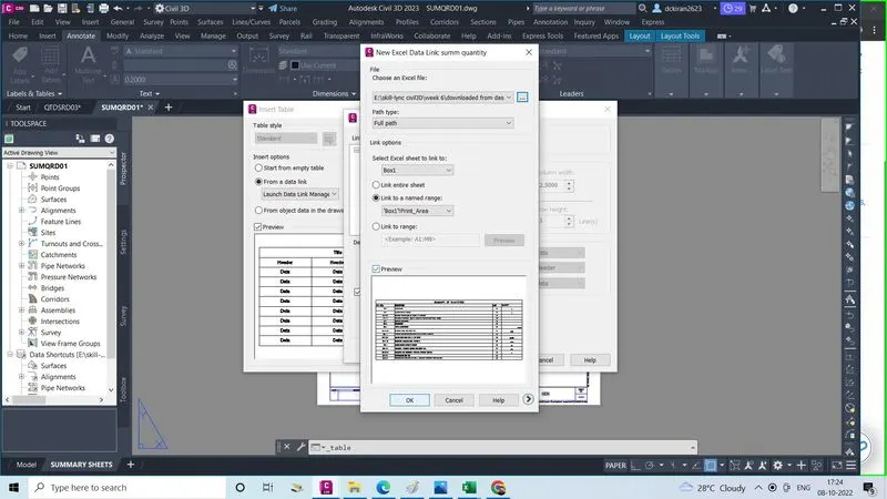
- Insert table sheet will open, in insert options select a data link,click lunch data link manager
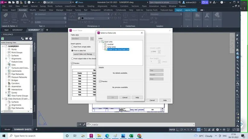
- One link type sheet will open in that
- Click on a "create a new excel data link"
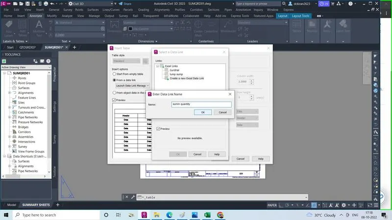
- Again a small sheet will open , in that enter data link name, give name their one bu one click ok
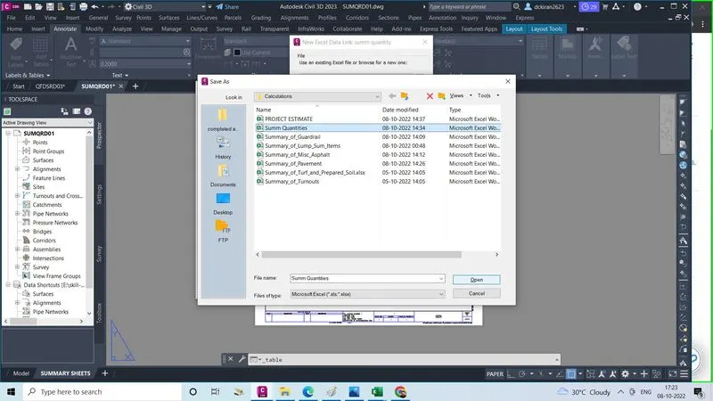
- Again new excel data link summ quantity sheet will open in that select the file ( excel like which name you gave first)
- Select the file summ quantities & Click open,& click on the preview & see,click ok,ok,ok
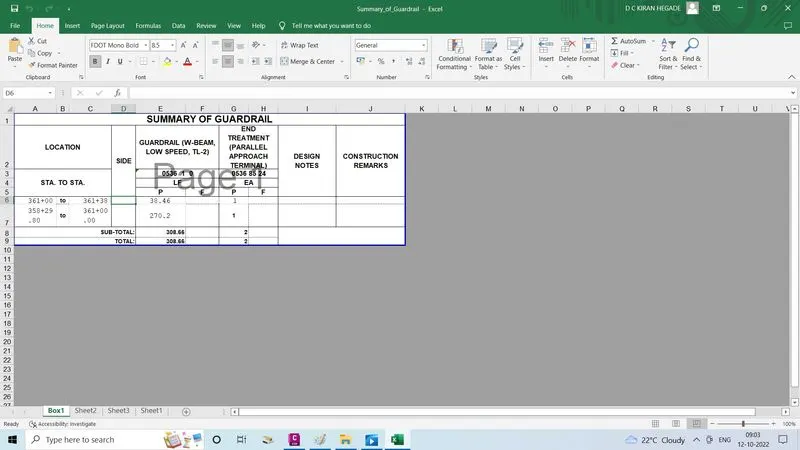
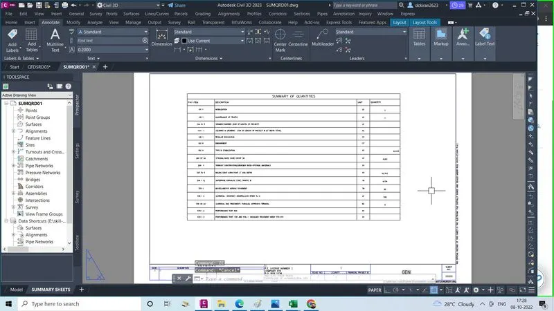
- Paste on the sheet, ZE enter, now quantity summary excel sheets into civil3D & layout is create
- Type command CTRL+4 the sheet set manger will open
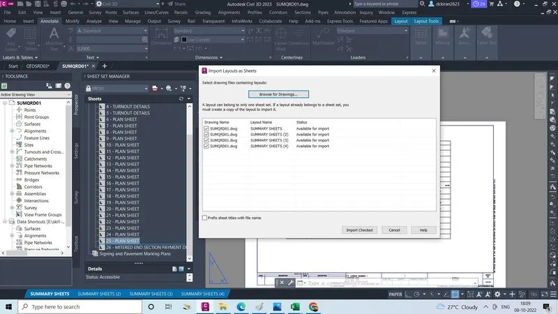
- Then select all layout and drage into a sheet set manager and place it after plan sheets import layout as a sheets ,sheet will open
- All layout is imported and select, click on import checked
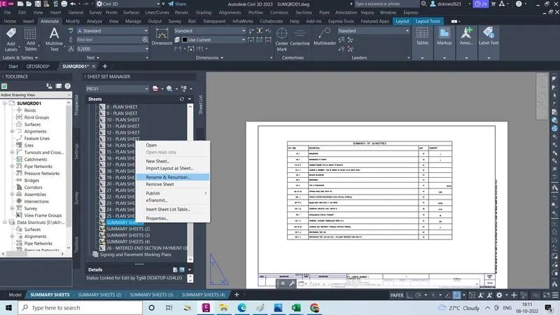
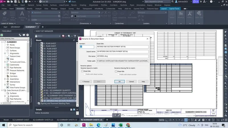
- Right click on these layout
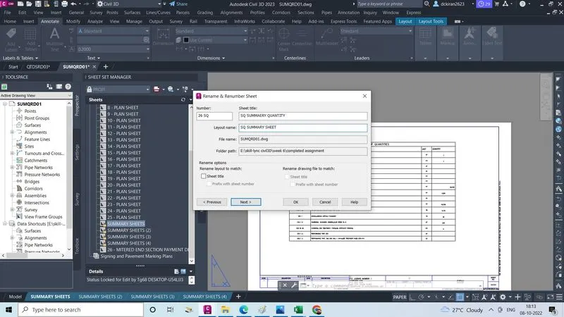
- Click on rename and renumber
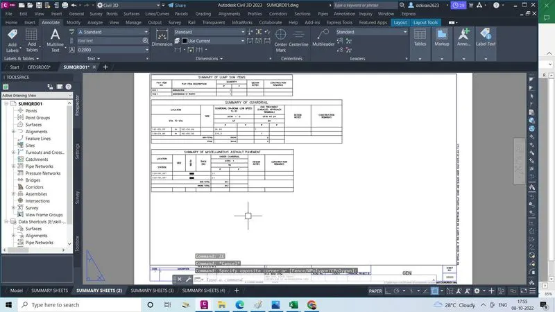
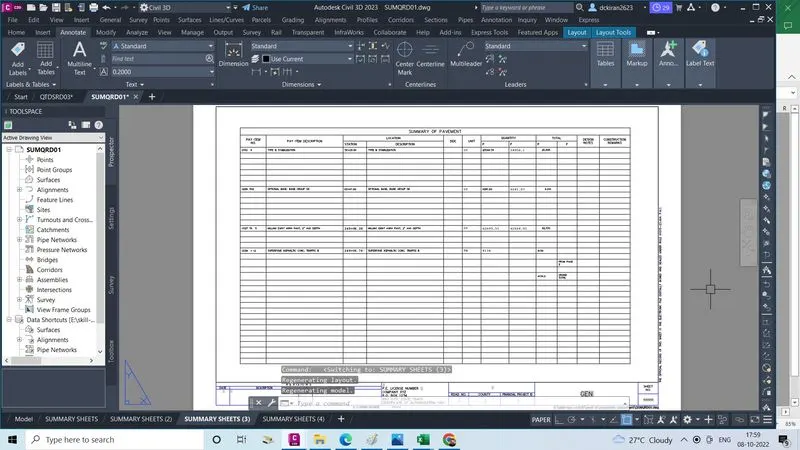
- Now do the same procedure for all quantitesAfter creating summary sheet layout
- After complettion of taking quantities of every items
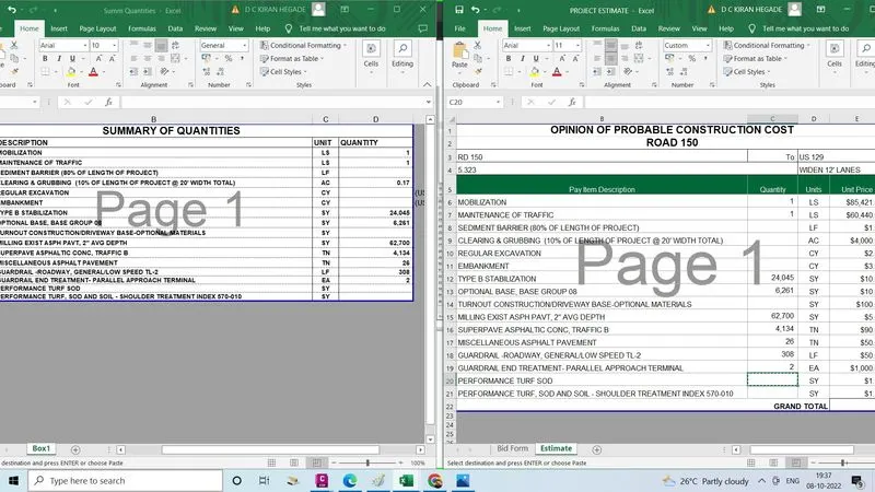
- We will first enter every item quantities "summary of quantities"page , in excel
- After entering in "summary quantites" enter all that quantites in "Estimate"page in excel also by the seing the summary of quantites
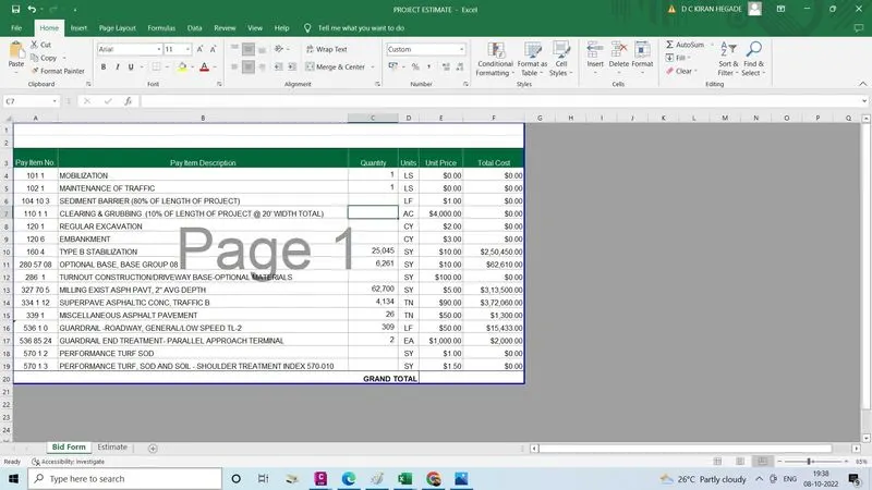
- After that we will only copy the "payitem no,payitem discription, quantities, unites"in the bid form not unit price, total cost because it left to contractor