Week 6 Challenge
Challenge 6
Q.Calculate the Pipe loads for the bridge shown in figure The width of bridge is 3m. The bridge is located in the banks of river Narmada. Two pipes are proposed on the bridge with one being 700 dia NB DI pipe and the other one being 200 dia NB DI pipe. The length of the bridge is 24m. Apply the calculated pipe load in Staad.pro
Answer
AIM: Analysis of the Bridge span of 24 m truss bridge for Pipe line of 700mm dia NB DI pipe and 200 mm dia NB DI as shown in the fig below
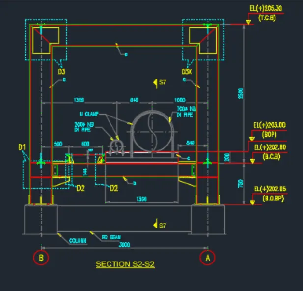
Fig1
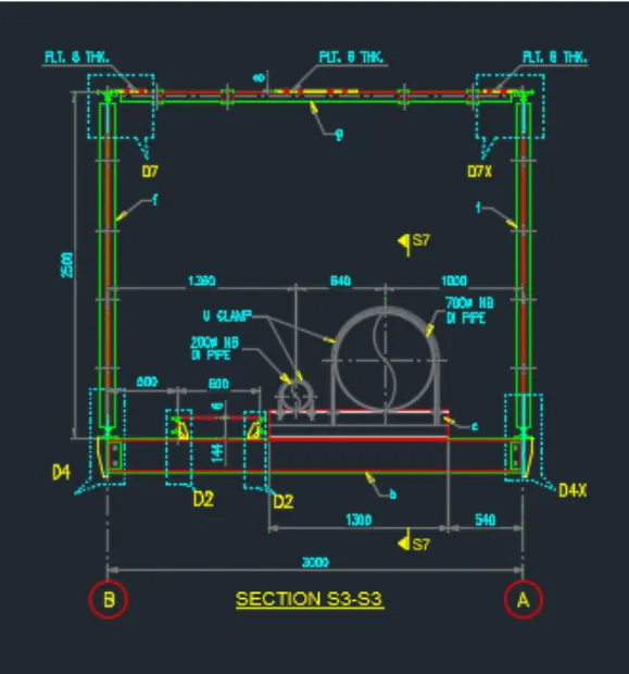
Fig2
INTRODUCTION : A pipeline bridge is a bridge for running a pipeline over a river or another obstacle. Pipeline bridges for liquids and gases are, as a rule, only built when it is not possible to run the pipeline on a conventional bridge or under the river.
However, as it is more common to run pipelines for centralized heating systems overhead, for this application even small pipeline bridges are common.
PROCEDURE:
Given Data
Span of the Bridge =1X 24 m
Width of the bridge =3m
Type of the bridge is truss bridge as shown in the fig3 below
Panel 8X3=24m
Steel bridge resting on 4 Nos of RCC columns and tie beam connected the two colums as shown in the fig
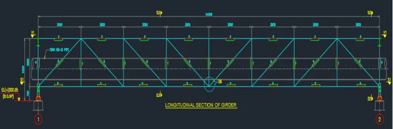
Fig3
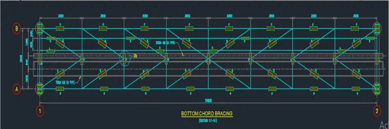
Fig 4
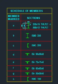
Fig 5
Letus model in Staad pro as per given data
Step-1
Model the bottom chord as shown in fig 4
- Create a node and another node also trough translation repeat at 3 m distance in Z-direction
- Connect the two node with beam element
- Create the beams for cross girder as per requirement at C/C distance of 3m in X direction with help of translation repeat
- Insert the mid node for intermediate gross girders for making bracing as shown in the model and connect the beam element for the same.
Step-2
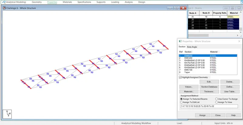
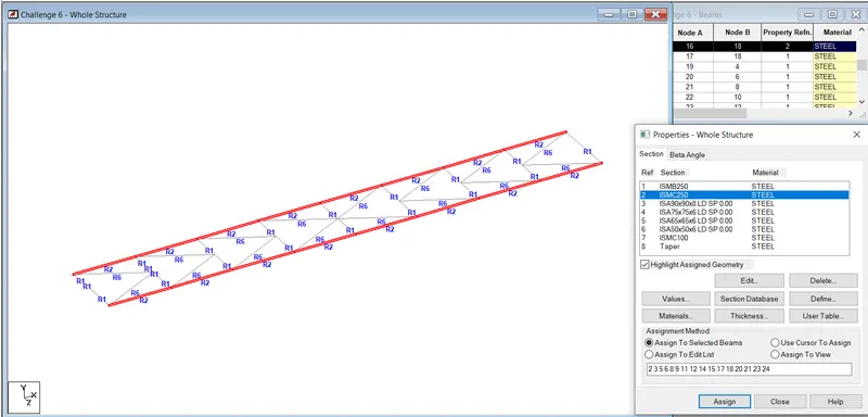
Define and assign section properties ISMC 200 for bottom chord and ISMB 250 for cross girders as shown in the fig below.
Step-3
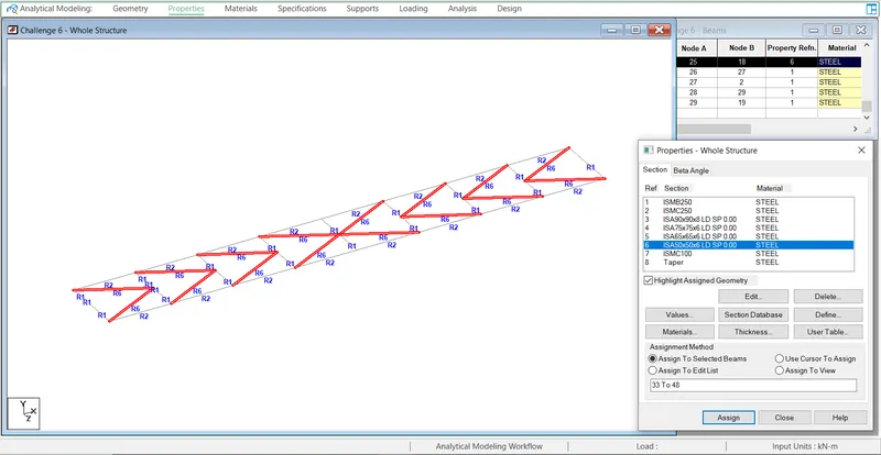
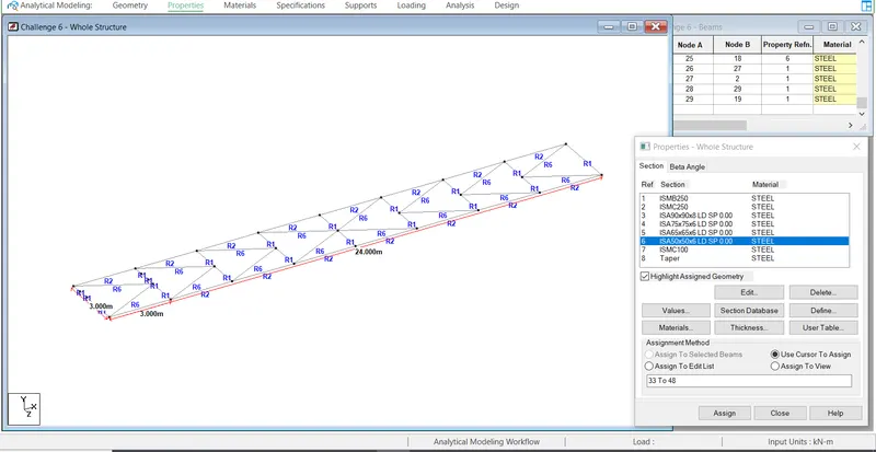
Assigned the ISA 50X50X6 for bottom bracing as per given data.
Step-4
This fig shown the dimension of the bottom chord
Step-5
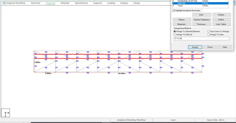
Bottom additional bracing D2 shown fig
Step-6
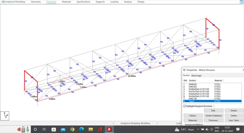
Vertical post for has been developed in the Y-direction from the bottom chord 2.5 m
End vertical post as assigned as per given data as build up section flange 368X16+200X12 mm thick and web 12 mm thick and end connectiong post of end verticals
Step-7
Load Calculation
Weight of 700 dia NB DI pipe 381 Kg/Rmt
Density of water=1000 kg/Cu-m
Weight of water
Pi/4X0.700X0.700X1X1000= 384 kg/rmt
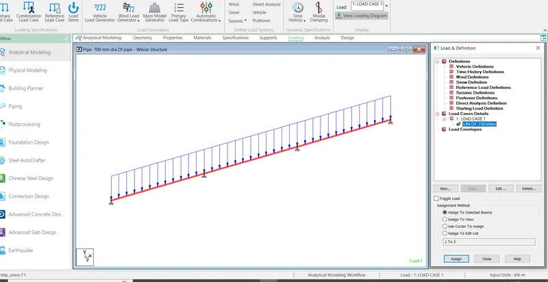
Total Weight of the pipe 381+384= 765kg/Rmt=7.65 KN/M
Weight of 200 mm Dia NB DI pipe 58.8 kg /Rmt
Wt of the water
Pi/4X0.2X0.2X1X1000=31.4 Kg
Total Wt of pipe with water
58.8+31.4=90.21 Kg/m=0.9021 Kn/m
Let us assume the pipe is resting cross girder of truss bridge, so reactions at supports can be loades on the nodes
Pipe can be cosidered as continuious beam with supports
Reactions
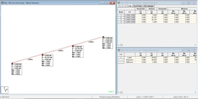
Maximum reaction is 25.197 KN from STAAD as shown fig above
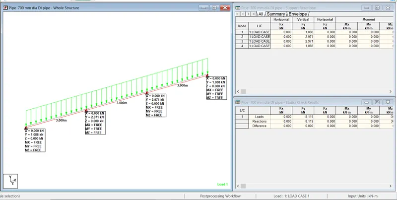
For 200mm pipe DI
The maximum reaction is 2.971 KN from STAAD below.
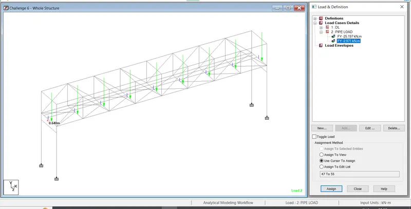
Letus apply the pipe loads on respective nodes
P1=25.197 KN
P2= 2.971 KN
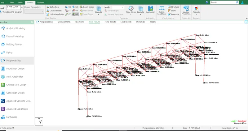
Results
Maxmum deflection 14.418 mm
Reaction at supports 99.81 KN
Maximum BM in Cross-Girder=17.714 KN-M
Maximum SF in Cross Girder=18.076 KN