Week-6 Calculate the Stretch Ratio by comparing the ELFORM (-2,-1,1,2) with Ogden_Material Model.
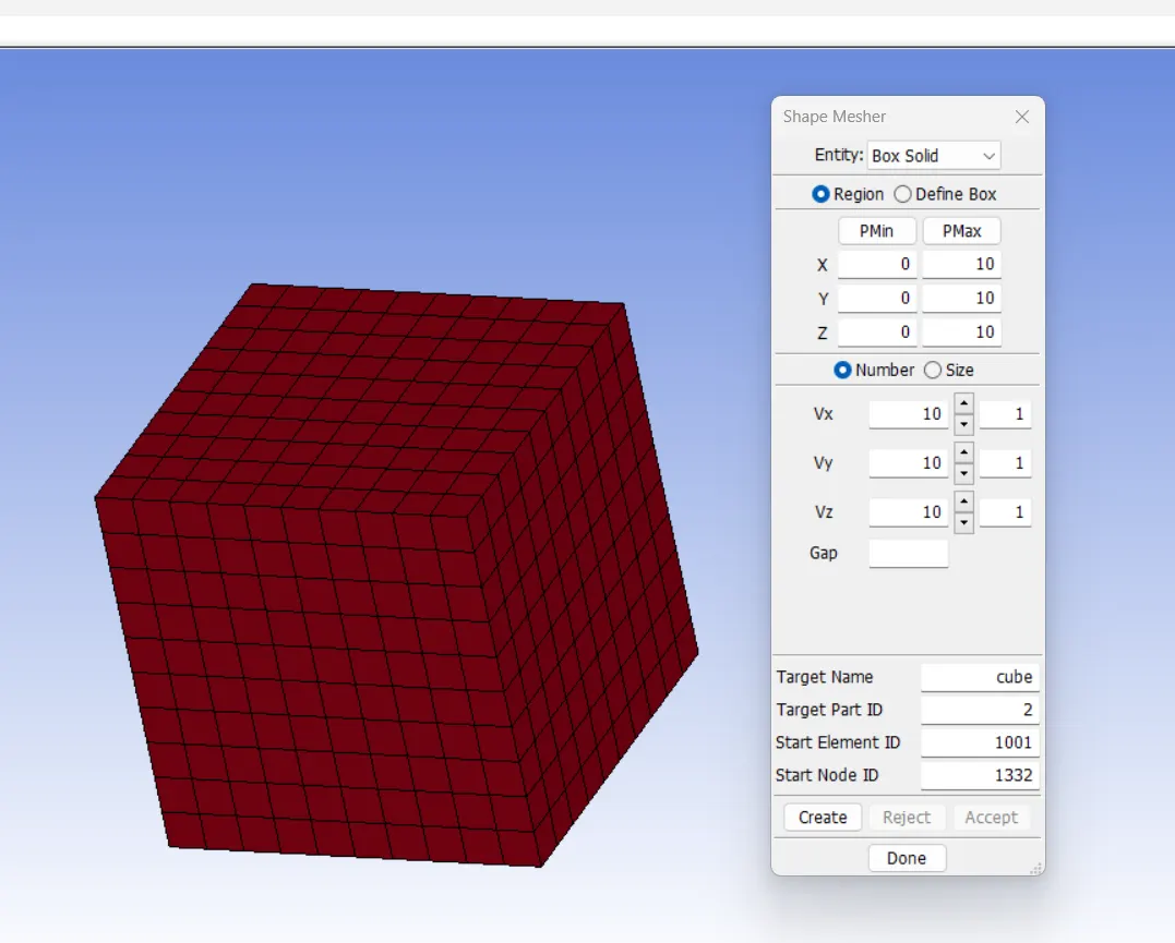
AIM: To create a block of 10mmx10mmx10mm dimension with 10 element for each direction and use the material card that is representative of material property. Compare the results for the simulation using ELFORM 1,2,-1,-2.
STRETCH RATIO: It is basically a ratio of the current length of the part to original length of the part. Then the engineering stress is called Nominal stress which basically considered as the constant area of cross section .Here is Hyperelastic material also the area of cross section reduces as we stretch it.
Stretch ratio= current length/ original length
Stretch ratio= 1+Engineering strain
So stretch ratio will always greater than unity.
True strain= ln(1+Engineering strain)
True stress=Engineering stress(1+Engineering strain)
True stress(nominal stress)= True stress/stretch ratio.
PROCEDURE:
STEP 1: CREATE CUBE.
element and mesh > shape mesher
Entity: Box solid
STEP 2: DEFINE SECTION.
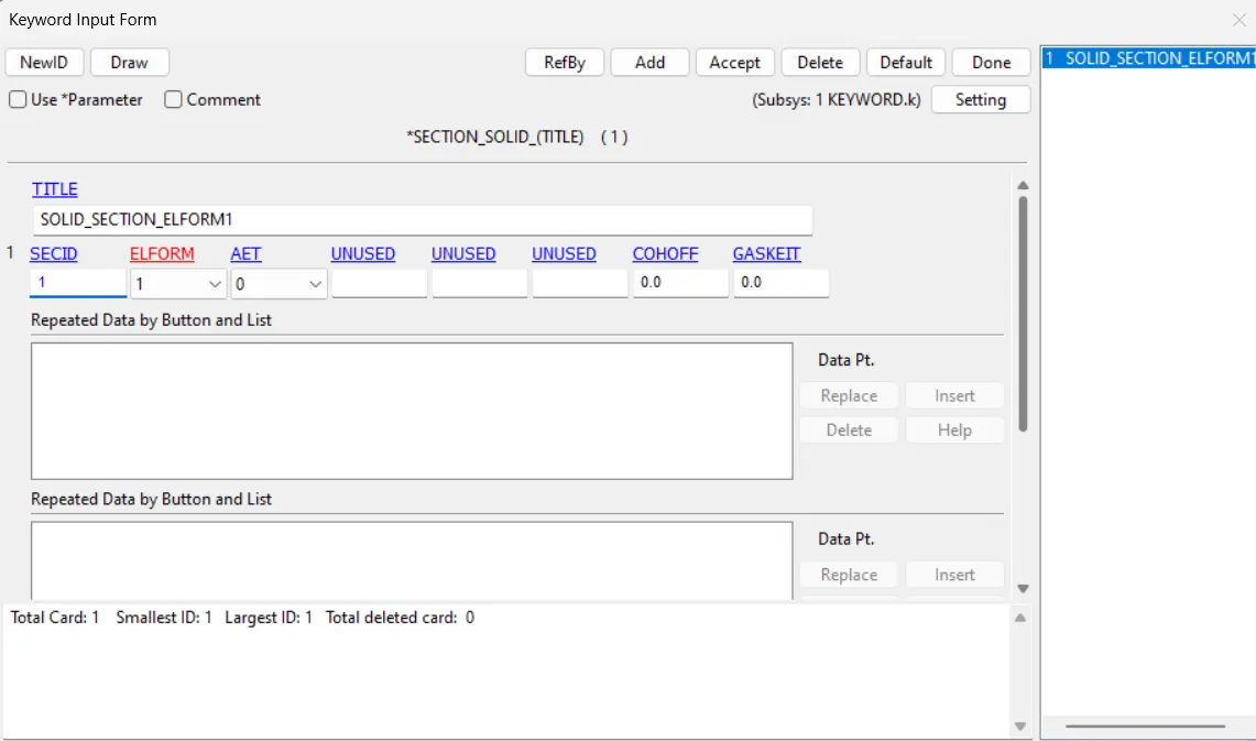
keyword manager > SECTION > SOLID
ELFORM=1
STEP 3: DEFINE BOUNDARY CONDITION.
Here we need to consider compression in other direction of the material , when one direction is pulled by a force.
Here we will fix the bottom and give motion to the set of nodes on the upper face.
For fixing the bottom face.
create entity > Boundary > Spc
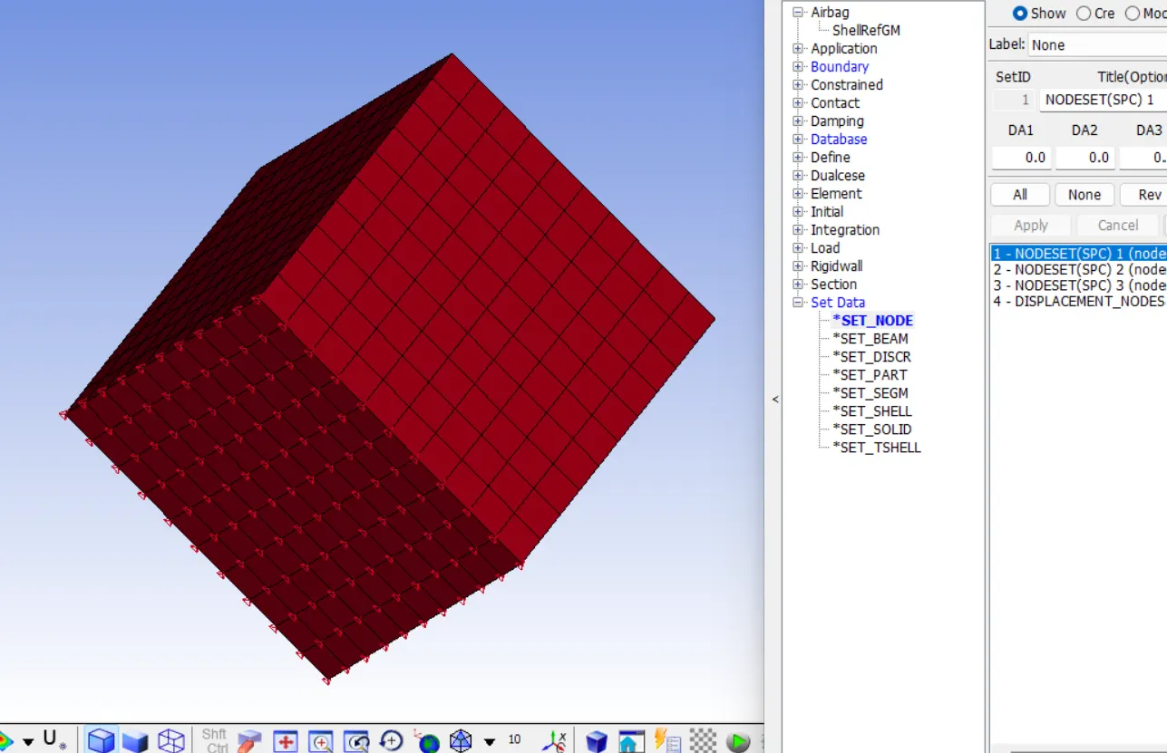
constraints are given for the different set of node in a way that cube can shrink X and Y direction upon tension in Z direction and also stick to its position.
STEP 4: DEFINE DISPLACEMENT.
Stretch ratio= 1+Engineering strain
Lets substitute the stretch ratio as 5 and L=10mm
5= 1+ dL/L
dL= 40mm
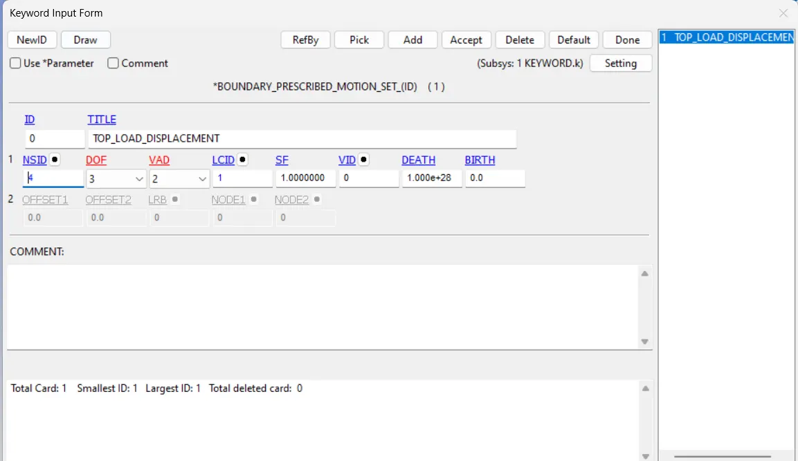
The displacement value for the cube face is 40mm and here we need to input the load curve as 50mm,
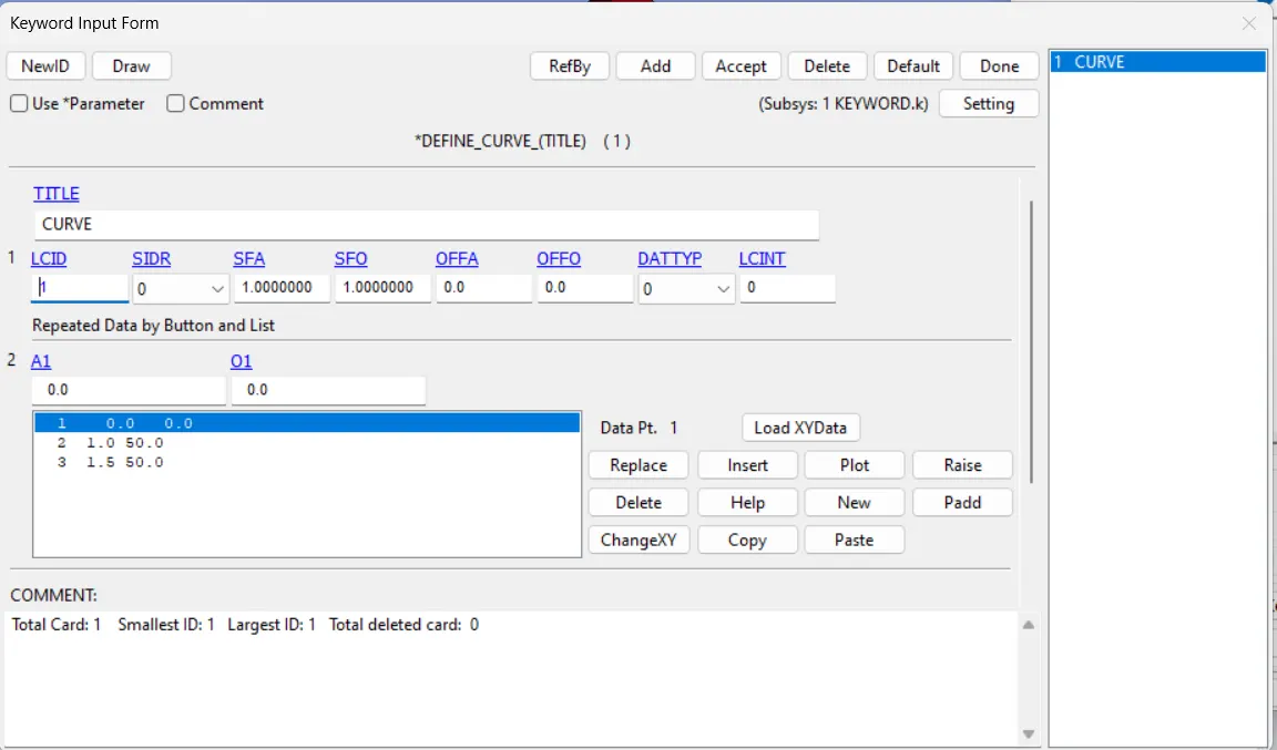
Here we want to define a node set in a face in which we need to apply the displacement.
And we will be defining this node set in the *PRESCRIBED_MOTION_SET. This will be ensure that our model will behave as it is under the real tensile test.
For create node set,
create entity > SetData > *SET_NODE
Then go to , All > BOUNDARY > *PRESCRIBED_MOTION_SET
STEP 5: DEFINE MATERIAL.
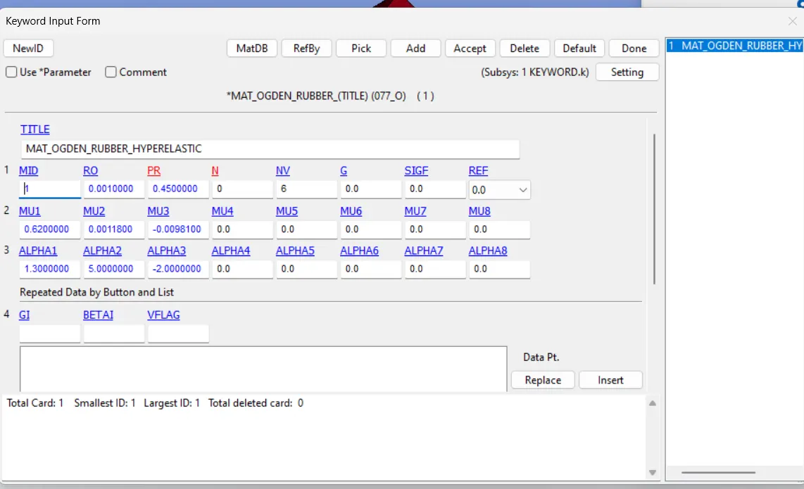
Model > Keyword manager > MAT > OGDEN_RUBBER
Add the parameter from given .k file
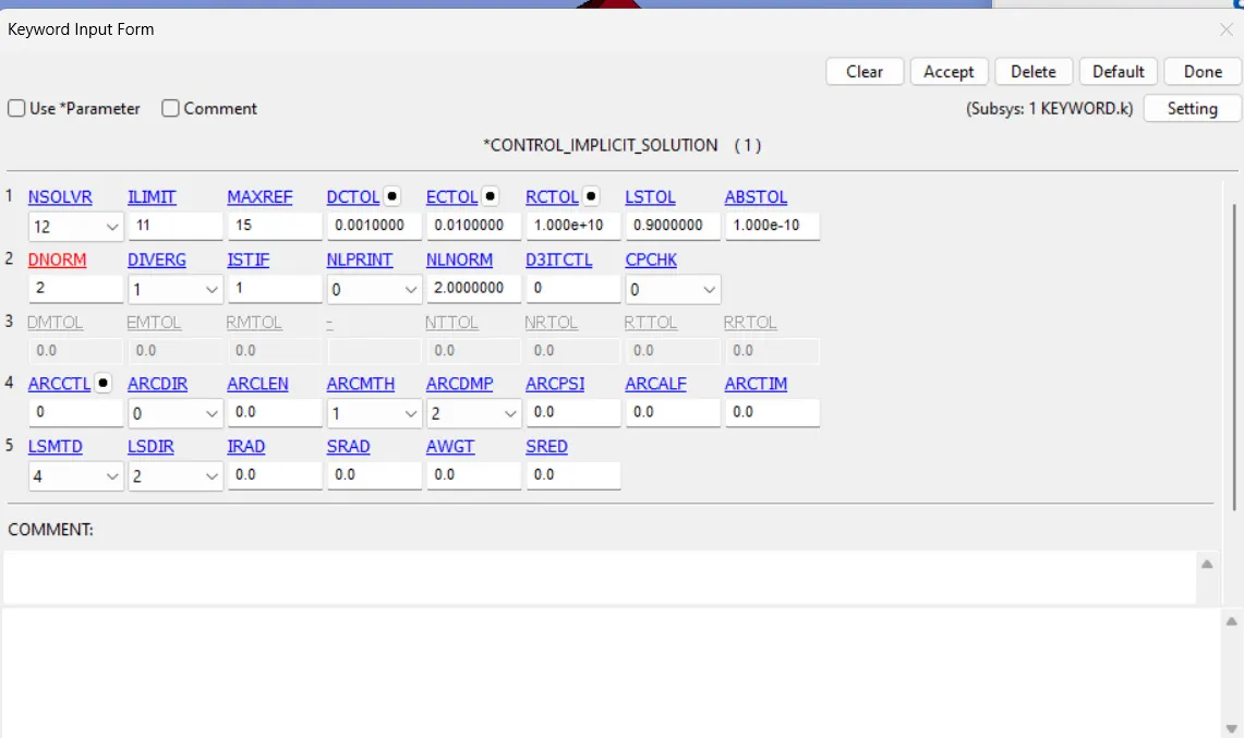
STEP 6: IMPLICIT CARDS.
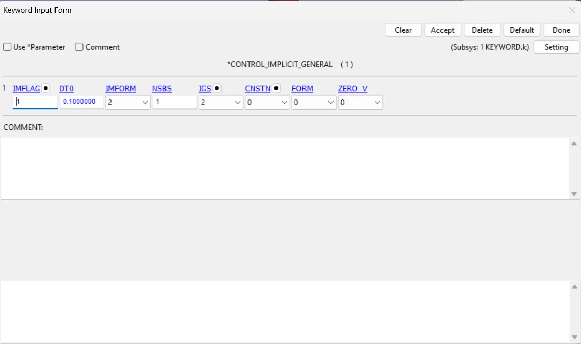
We need to convert the card for Implicit analysis. There are three main cards to be inserted to the system.
1. *CONTROL_IMPLICIT_GENERAL : We need to set IMFLAG as 1 , Which tells the solver to switch to implicit analysis mode.
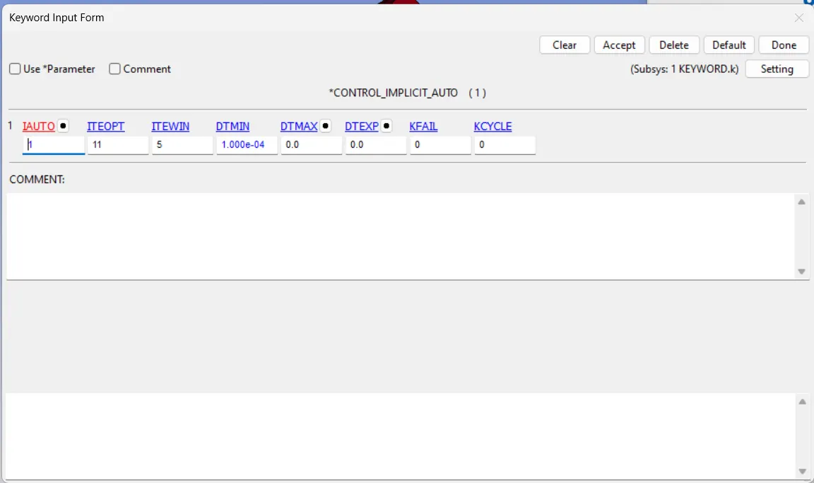
2. *CONTROL_IMPLICIT_AUTO : In this card we need to set IAUTO=1 ,Which basically means automatically adjusted time step size.
3. *CONTROL_IMPLICIT_SOLUTION : This is used for Non linear problems.
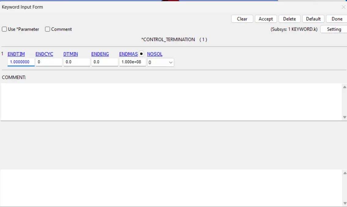
STEP 7: DEFINE TERMINATION TIME.
STEP 8: DEFINE OUTPUT
DATABASE > ASCII and BINARY_D3PLOT, DT = 0.1
And also select an element from the load face and set a card of DATABASE > HISTORY_SOLID. And we can see get the values at the elout file for the data.
=======================CONCLUSION====================================
EXPLANATION:
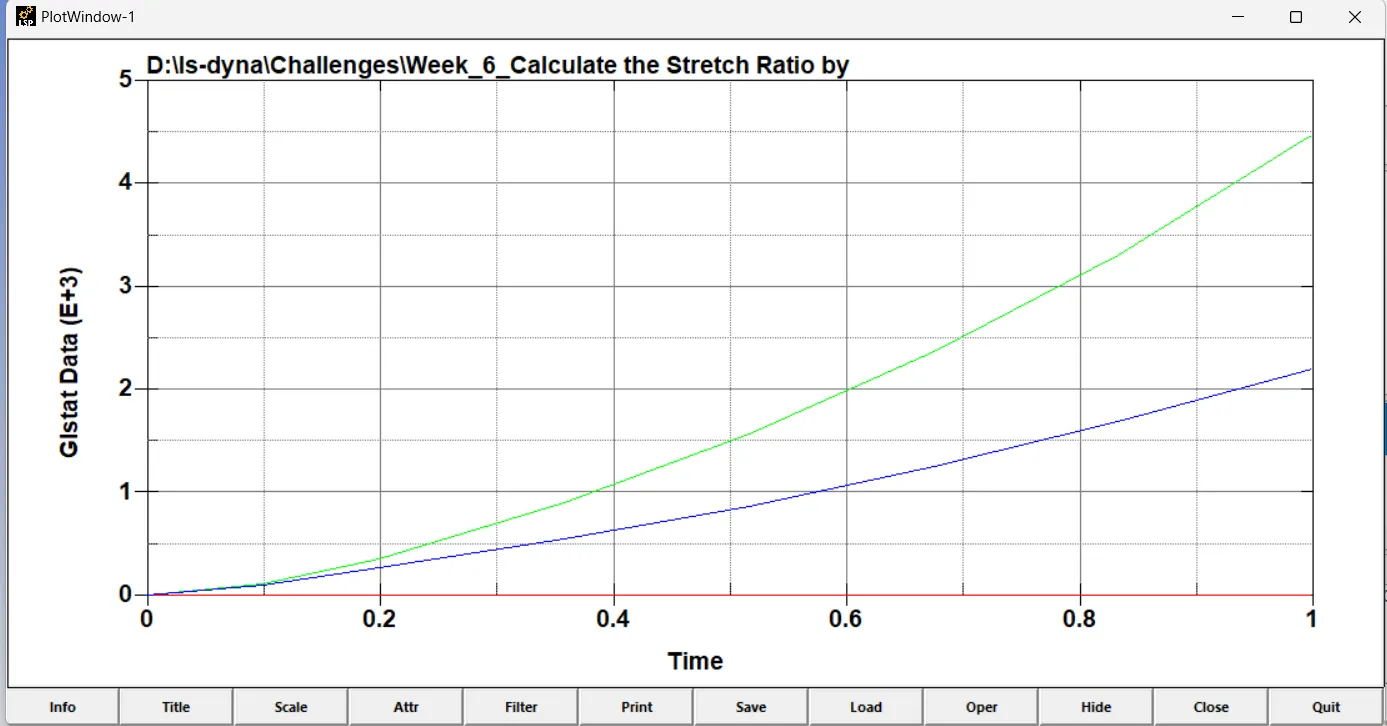
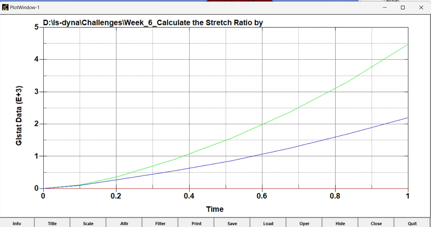
The graph we got here for different ELFORM values is nearly the same. Different ELFORM serves different purposes. Since the problem is not so complex every element formulation succeeds in giving almost the same results. All the plots above show the maximum Engineering stress value of 1Mpa.
GLSTAT GRAPH FOR DIFFERENT ELFORMS(KINETIC,INTERNAL,TOTAL ENERGIES)
ELFORM 1
ELFORM 2
ELFORM -1
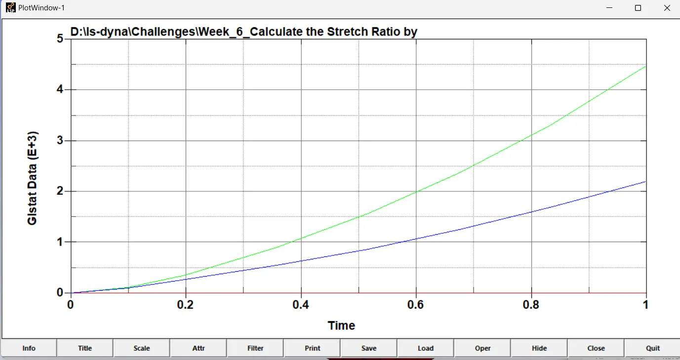
ELFORM -2
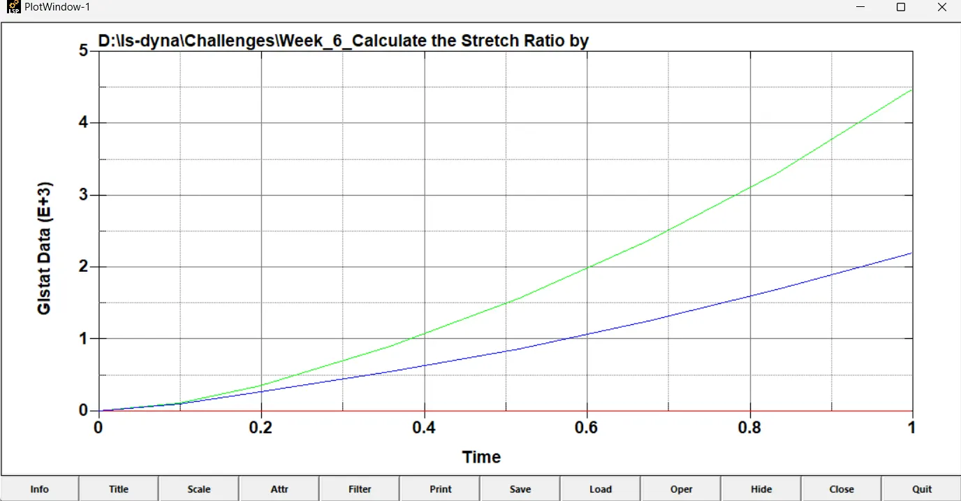
HERE WE CANNOT SEE ANY MUCH DEVIATION FROM THE PLOTS.
------------------------------------------Thank You---------------------------------------------