Week-6 Calculate the Stretch Ratio by comparing the ELFORM (-2,-1,1,2) with Ogden_Material Model.
Aim: To perform the tensile test of the cube and compare the stress and stretch graph for different Element formulation (-2, -1, 1, 2) for Ogden material.
Introduction:- In this challenge, we will perform the tensile test of a cube made up of Ogden material. Ogden material is nonlinear in characteristics. A 3D model with a 10mm*10mm*10mm dimension with 10 numbers of elements on each side is created. An implicit approach is used to analyze stresses and strains. We will compare the Engineering stress and Stretch graph of different element formulation.
In the analysis, the post-processing results contain True stresses and Strains. To convert the True Stress and Strain into Engineering Stress and Strain, the following equation is used-
True Strain `ε_T=ln(1+ε_E)`
Engineering Strain `ε_E= e^(ε_T )-1` ----------------------------------(1)
True Stress `σ_T=σ_E (1+ε_E)`
Engineering Stress `σ_E= σ_T/((1+ε_E))` -------------------------------(2)
Procedure-
1. Modeling and Material- A 3D model is created on the basis of given dimensions.
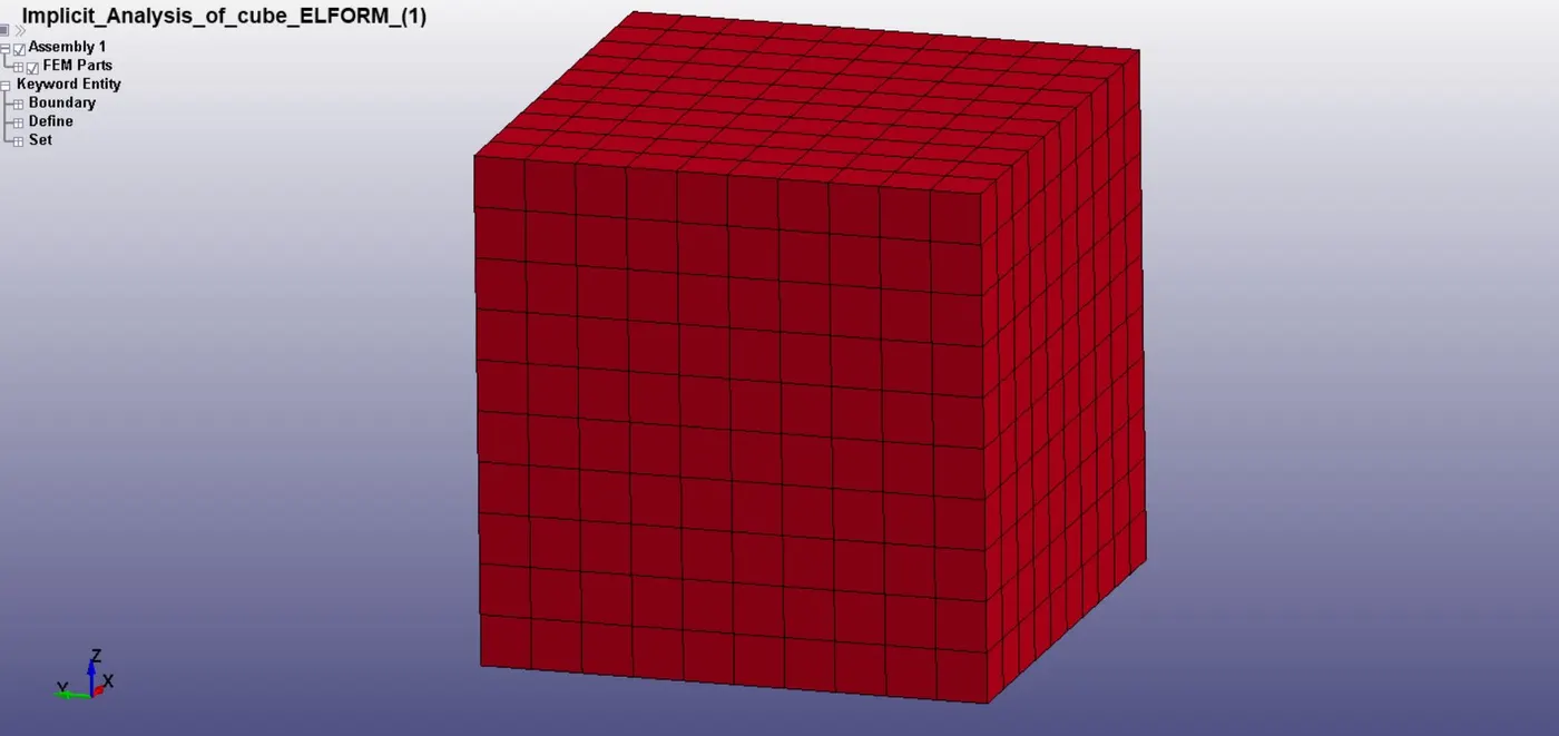
Fig 1:- 3D Model
The material for this model is Ogden. A solid section is created with different element formulation (-2, -1, 1, 2) to compute the stretch ratio.
2. Boundary Condition- To perform the tensile test, displacement is applied to one face in the positive z-direction.
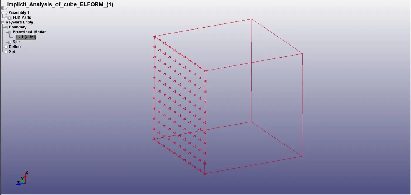
Fig 2:- Displacement applied in the positive z-direction
If we will restrict all dof on the opposite side then it will show inaccurate results. To perform precise simulation a suitable constraint is applied on the face to restricted motion in the z-direction-
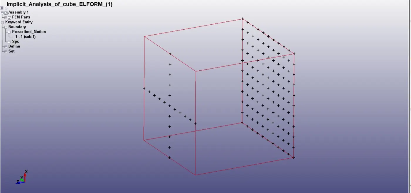
Fig 3:- Constraints
3. Solver:- Implicit solver is used to perform the simulation. *CONTROL_IMPLICIT_AUTO and *CONTROL_IMPLICIT_GENERAL cards are defined here.
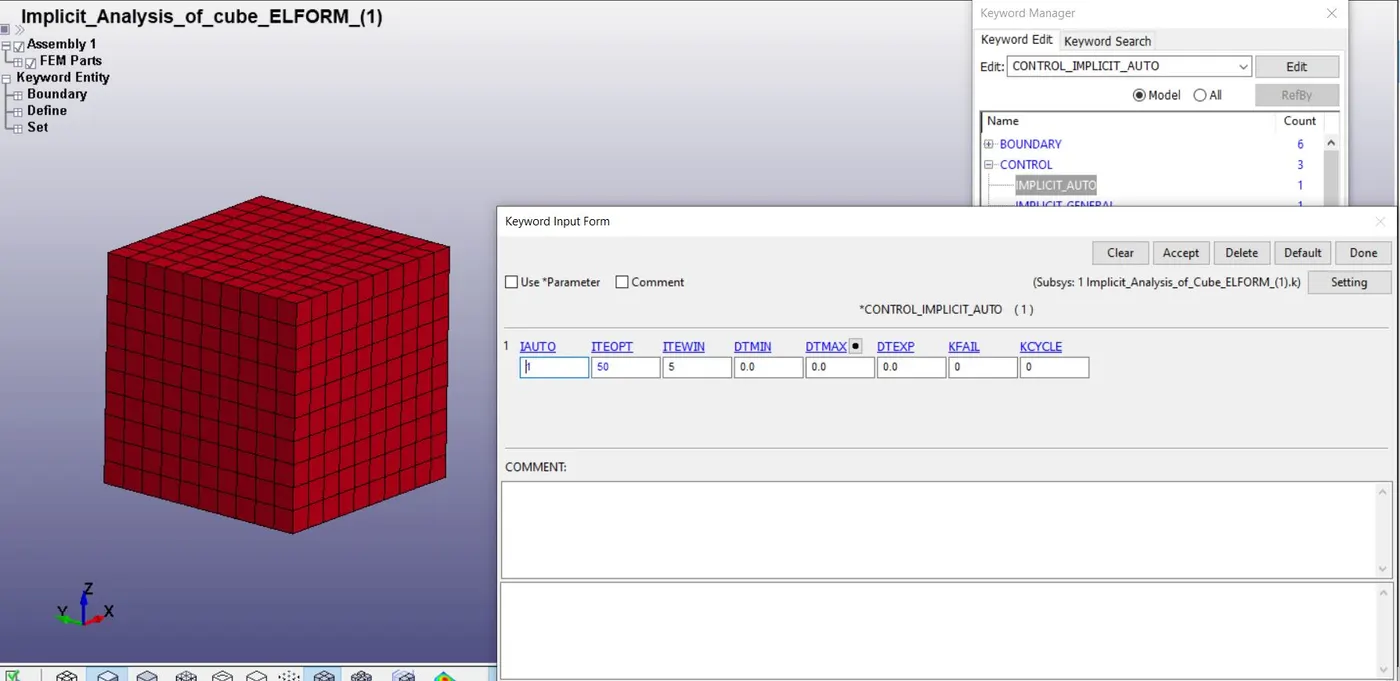
Fig 4:- Control Implicit Auto Card
Control Implicit Auto card is used to control the time step size in the problem. For this simulation, optimum equilibrium iterations are 50, and the iteration window is 5.
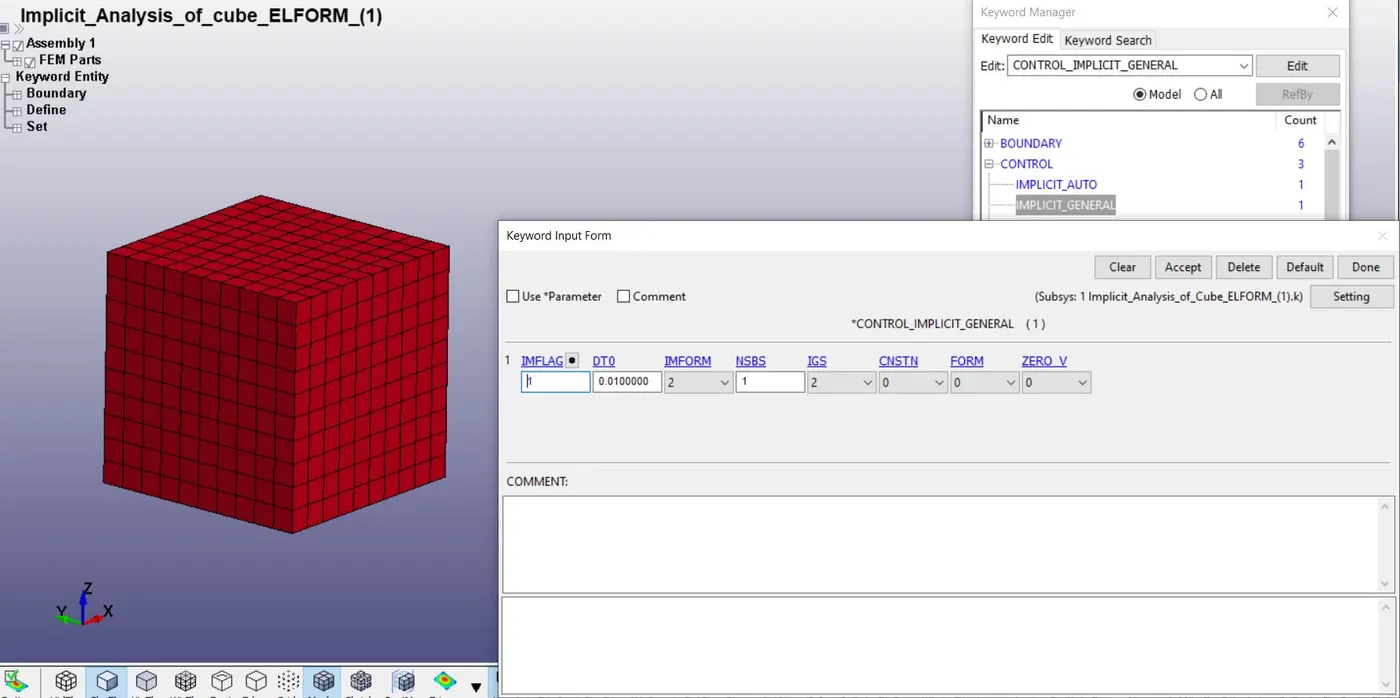
Fig 5:- Control Implicit General Card
Control Implicit General card is used to define whether our simulation is going to solve with the implicit or explicit solver. IMFLAG=1, activate the implicit solver.
4. Database:- For post-processing results, BINARY D3_PLOT and GLSTAT are selected to analyze the various stresses and material energies. Control termination time is taken as 1ms.
5. Results:-
A. Stress and Strain curve:- The displacement is given in z-direction so the graph is plotted between z-stress and z-strain. From the graph, it can be analyzed that the behavior of the Ogden material is like hard rubber.
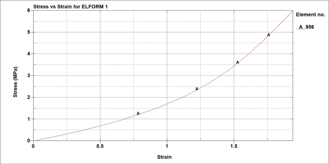
Fig 6:- Stress vs Strain Curve
B. Stress vs Stretch curve:- The curves between stress and stretch are plotted for different element formulation.
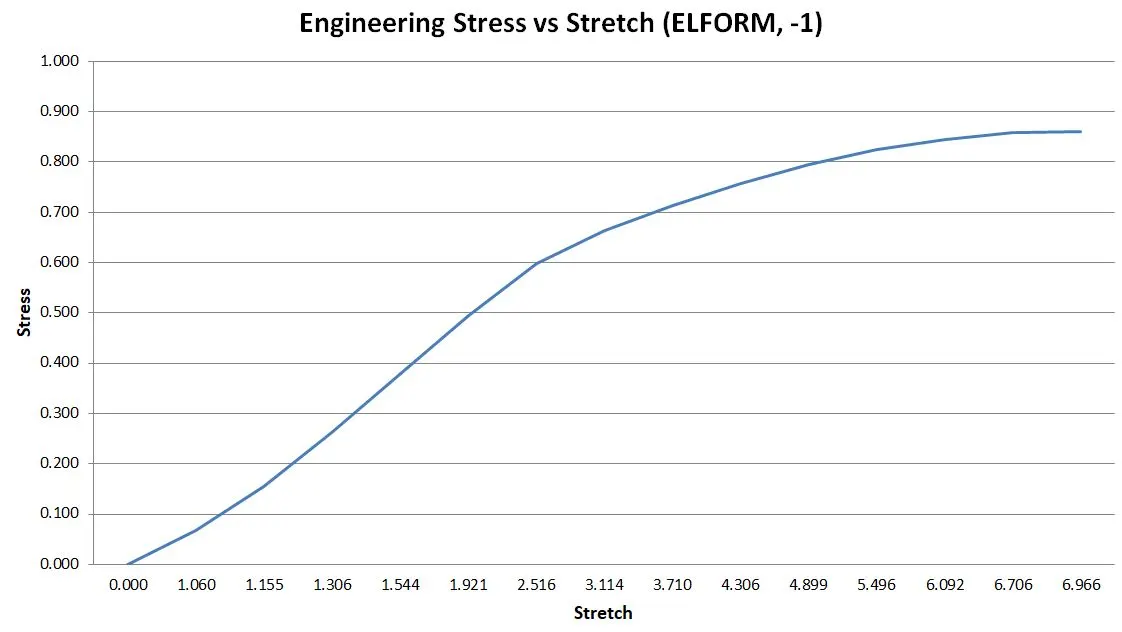
Fig 7:- Engineering stress vs Stretch curve for ELFROM (-1)
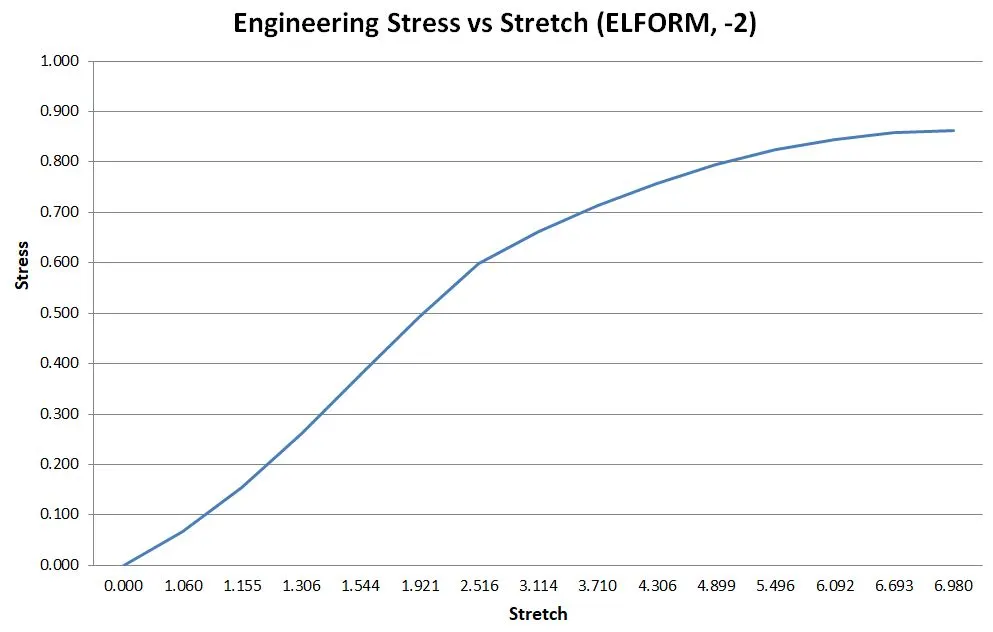
Fig 8:- Engineering stress vs Stretch curve for ELFROM (-2)
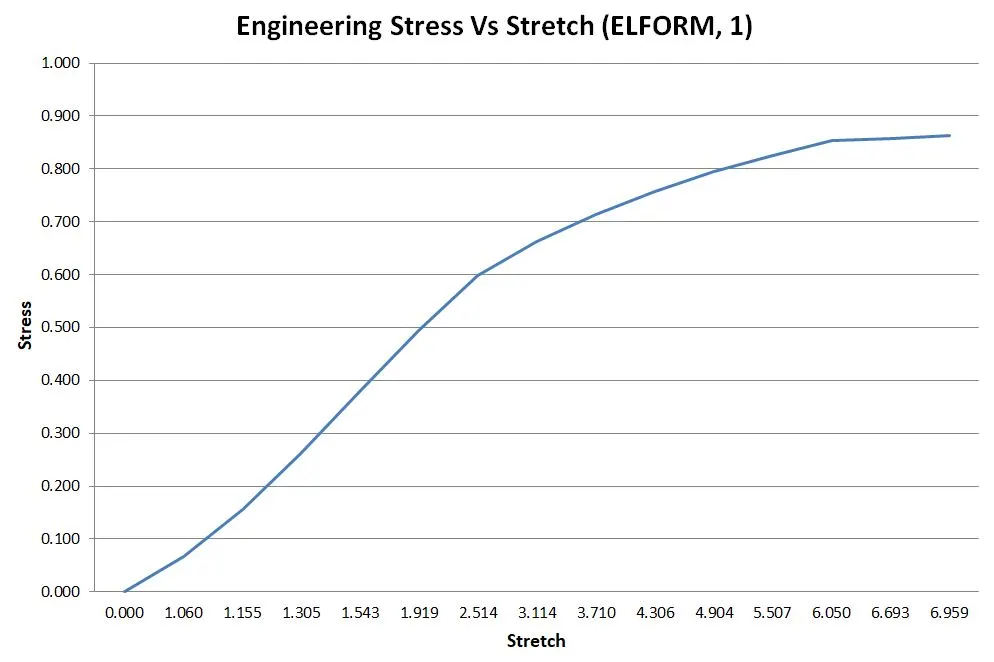
Fig 9:- Engineering stress vs Stretch curve for ELFROM (1)
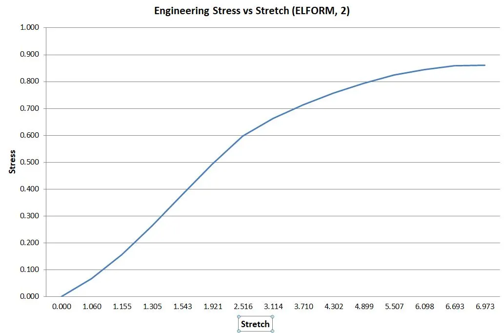
Fig 10:- Engineering stress vs Stretch curve for ELFROM (2)
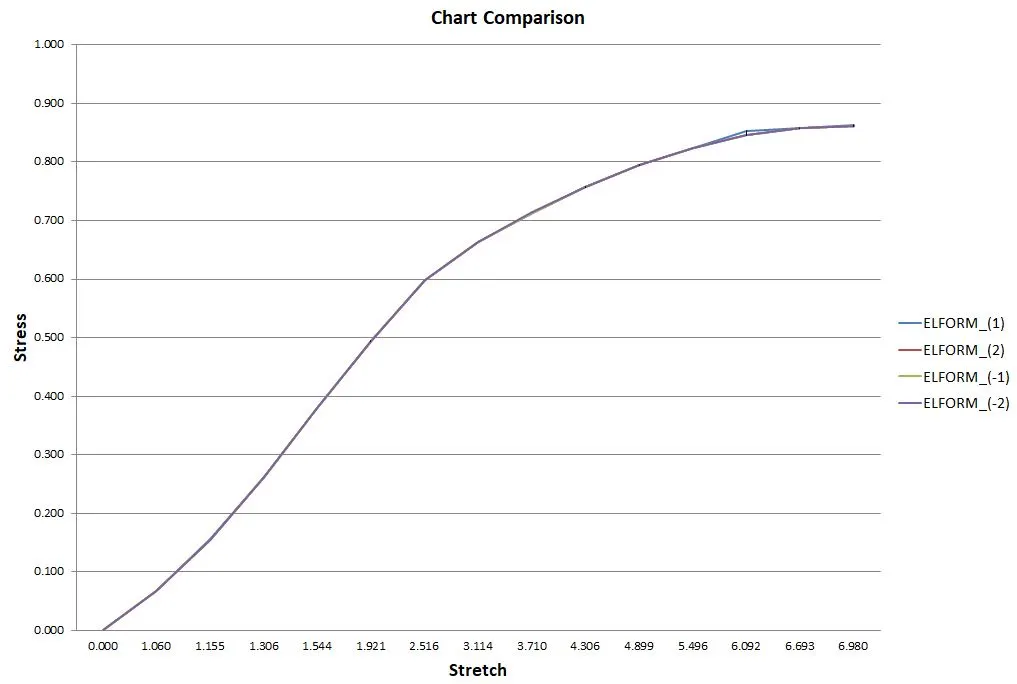
Fig 11:- Comparison of the curve for different element formulation
From fig 11, it can be concluded that the curve plotted between stress and stretch is almost the same for all element formulation due to a simple geometry problem. For complex geometry, the curves will be different for different element formulation.