Week - 5 - Modelling Spotwelds
OBJECTIVE- To analyze the crash simulation of spotweld between two shell parts using beam element and solid element. And find out the directional stress, strain, sectional force, axial force, and sheer force.
Unit System- Basic unit gm, mm, ms
1. Model- For this challenge, two shell part is given-
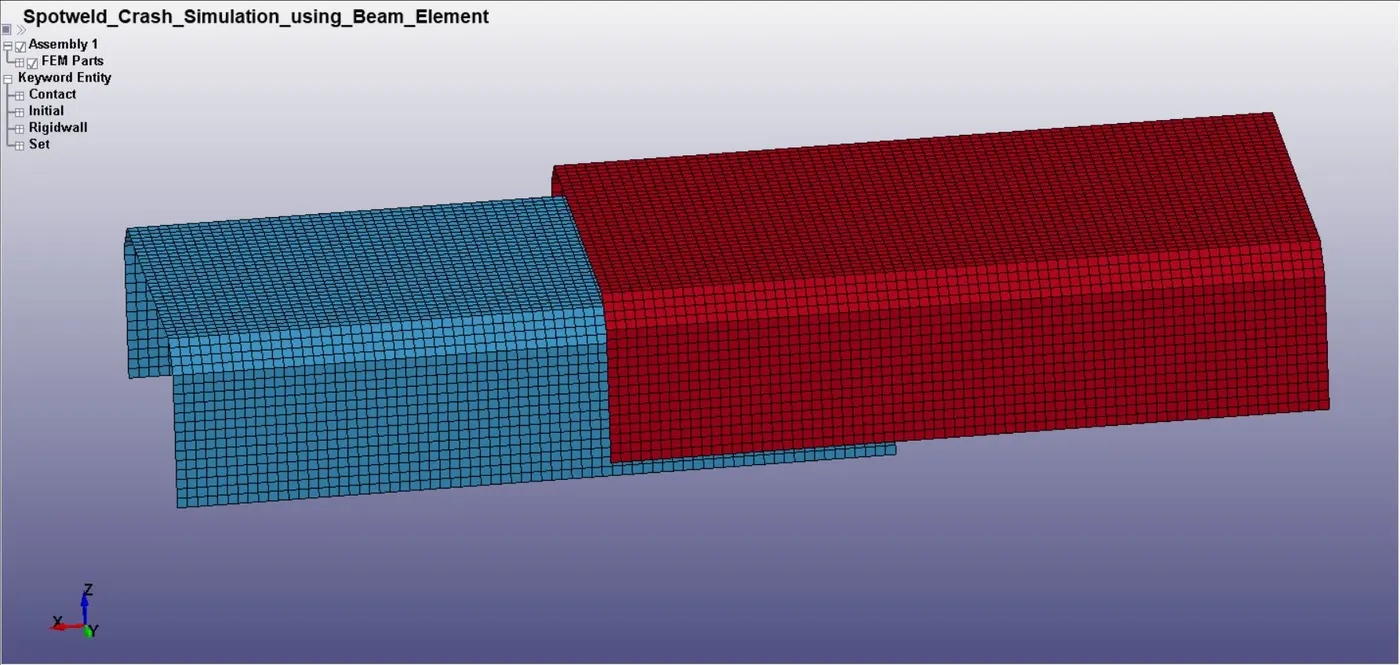
Fig 1:- Shell Model
In this model, six spotweld is created using the beam element on the desired set of nodes. Beam element can be created using *ELEGEN card. The location of the beam element is at the middle of the two shell parts given below-
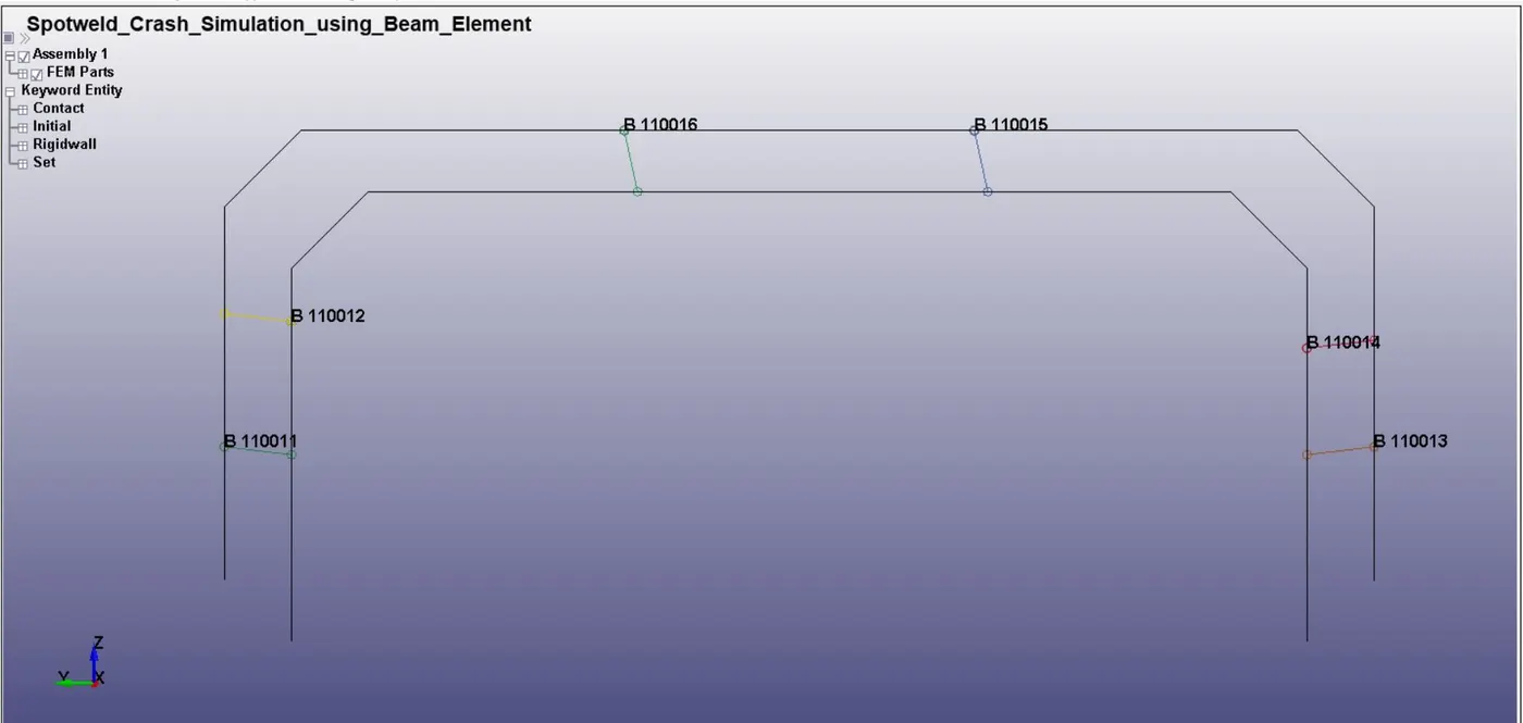
Fig 2:- Location of the beam element
2. Section and Materials
The model is having two shell parts and beam elements. *SECTION_SHELL is selected for shell parts with Element formulation 16 and *SECTION_BEAM for beam element with Element formulation 9. Steel and spotweld material is assigned for shell and beam elements respectively. The properties of spotweld material are listed below-
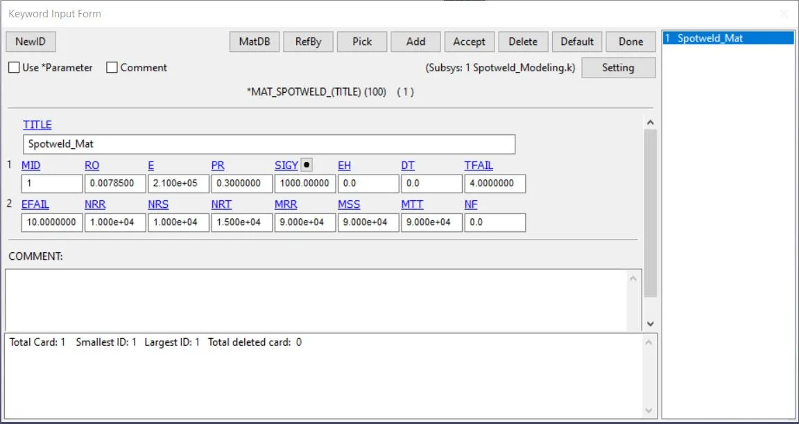
Fig 3:- Properties of Spotweld material
TFAIL is a failure time of the spotweld element. It is better to keep this time as half of the termination time.
After this, the sections and materials are assigned to shell parts and beam elements.
3. Rigidwall and Velocity- To simulate the crash analysis of spotweld, a rigidwall is created using *RIGIDWALL card and the initial velocity of 13.889 mm/ms is given to the model in positive x-direction towards the rigidwall. A node-set id is created using the complete model and assigned in NSID.
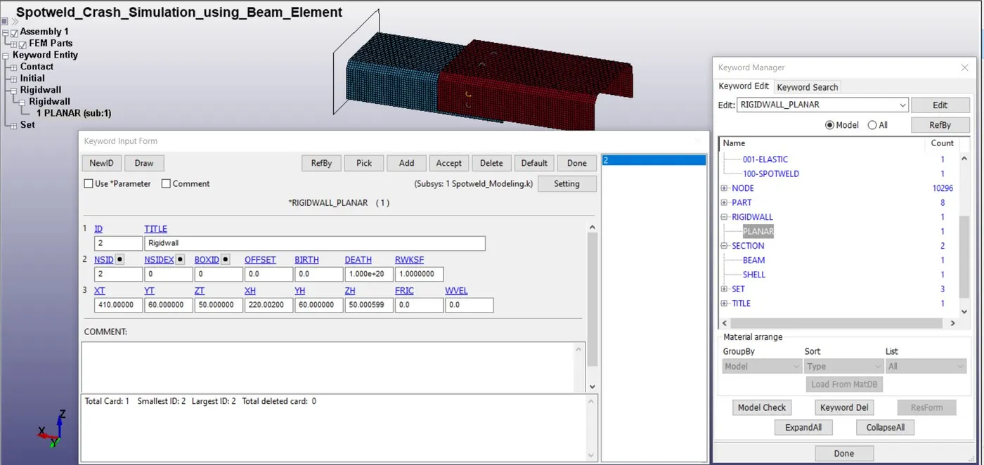
Fig 4:- Rigidwall parameter
4. Contact- Here, we need to create two contacts. First contact between spotweld and shell parts which is created using *CONTACT_TIED_SHELL_TO_SURFACE. The second contact is created for two parts using *AUTOMATIC_SINGLE_SURFACE. The purpose of the second contact to restrict the penetration of the shell parts into each other.
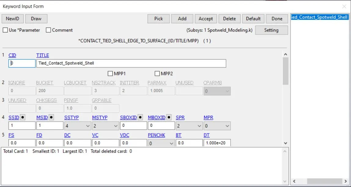
Fig 5:- Contact between spotweld and shell parts
5. Control and Database- In the control card, Hourglass Energy and termination are defined. Termination time is taken as 6ms. In the database card, ASCII option, Binary d3 plot, and extent binary are defined for every 0.5ms interval.
6. Spotweld Modeling using Solid Element- To compare the results of spotweld using beam element and solid element, we have to create a model with solid element spotweld. In this model, six solid elements have been created using the same procedure as mentioned above.
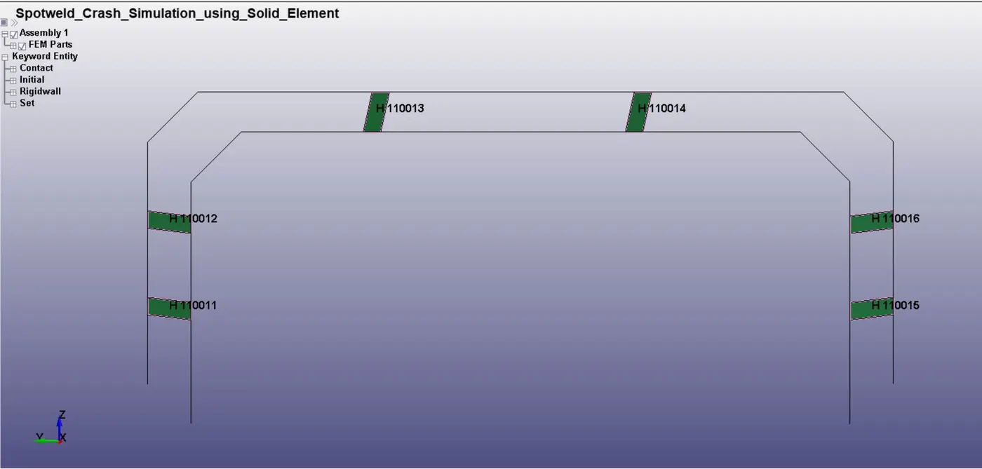
Fig 6:- Spotweld using the solid elements
7. Comparison of Results-
7.1 X Directional Stress-
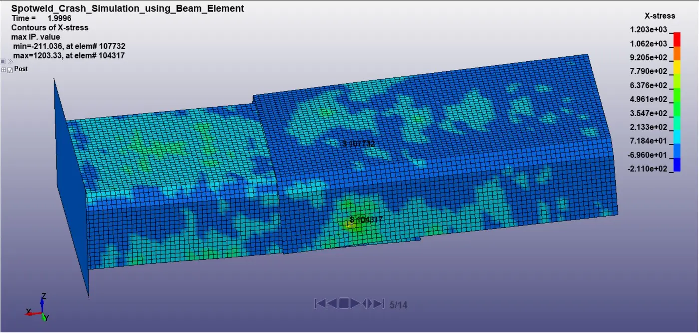
Fig 7:- X stress in the model having a beam element
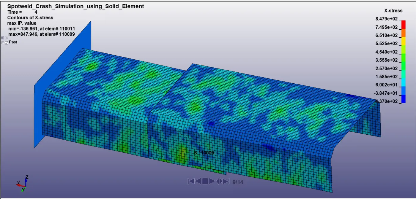
Fig 8:- X stress in the model having the solid element
From the above figures, we can see that the x- stress generated in the model having a beam element is about 1203MPa whereas in the solid element spotweld model is about 847MPa. The location of the maximum stress in both the model is near the side bottom spotweld. The beam element spotweld experiencing more stress due to the small area.
7.2 X- Directional Strain -
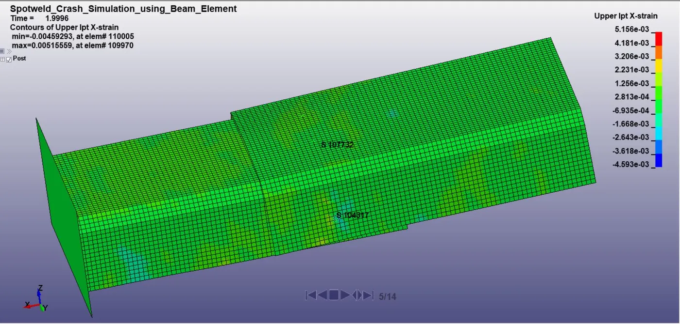
Fig 9:- X strain in the model having beam element
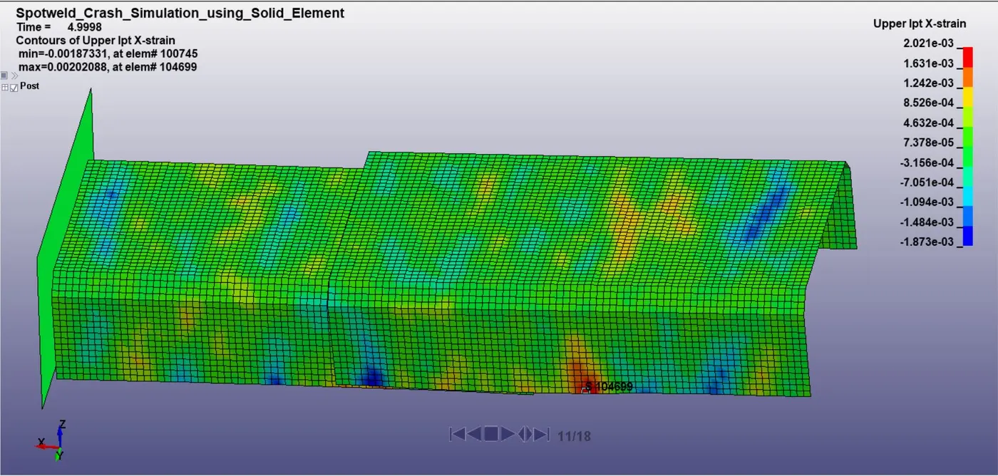
Fig 10:- X strain in the model having the solid element
X-directional strain developed in both models can be analyzed from the above figures. The spot weld model with beam element is subjected to more strain as compared to the solid element. This is happening due to the stiffness of the solid elements which is more than the beam element.
7.3 Sectional Forces-
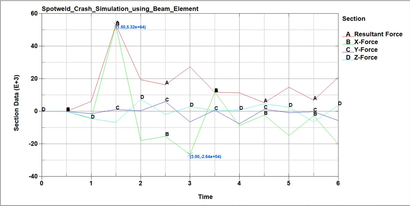
Fig 11:- Sectional forces in Model having beam element spotweld
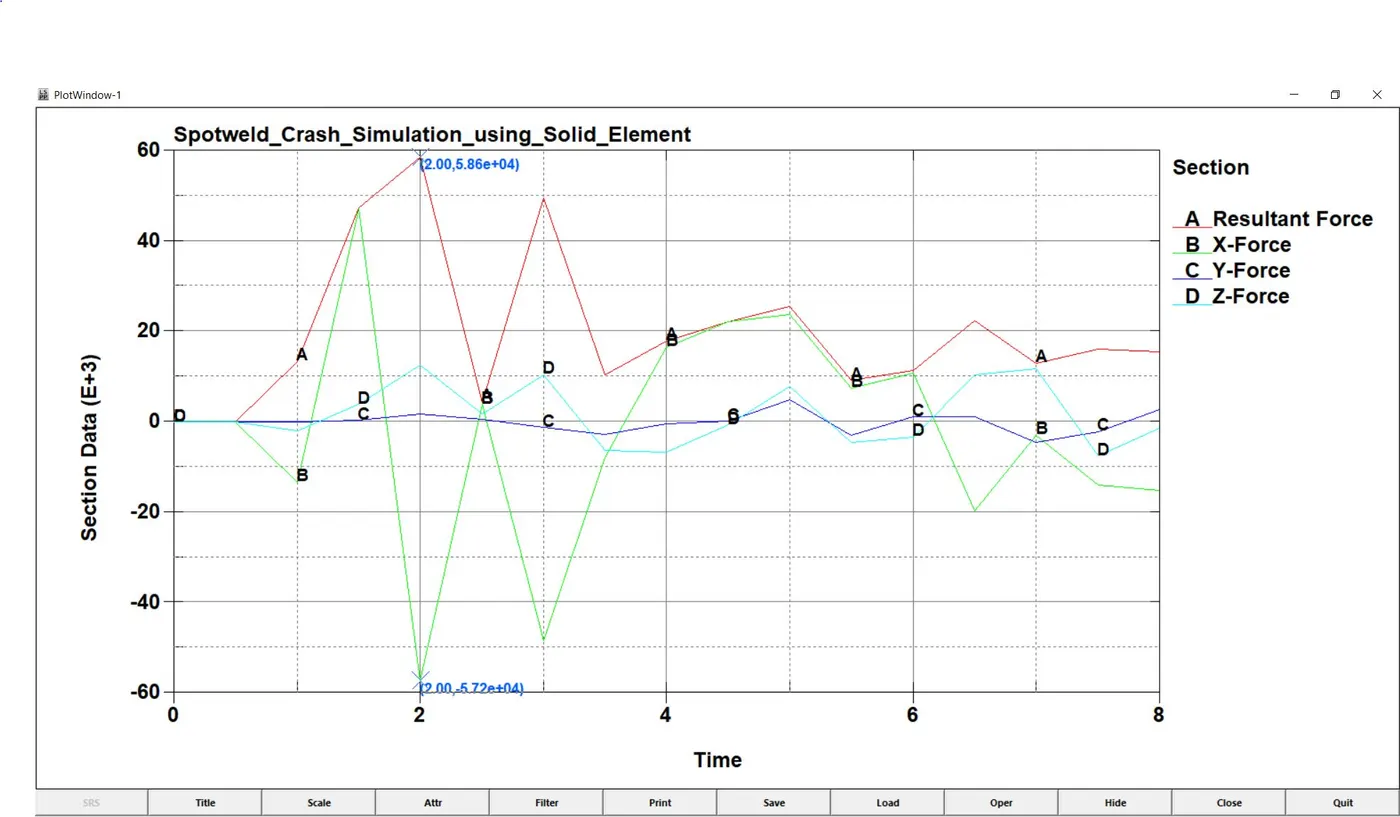
Fig 12:- Sectional forces in Model having solid element spotweld
Sectional force is the amount of reaction force generated after the impact. In the above image, we can conclude that the spotweld with beam element is having more sectional force at the mid as compare to the solid element.
7.4 Energies- In this part, different energies namely kinetic energy, internal energy, total energy, hourglass energy, and sliding energy are compared with the solid element and beam element.
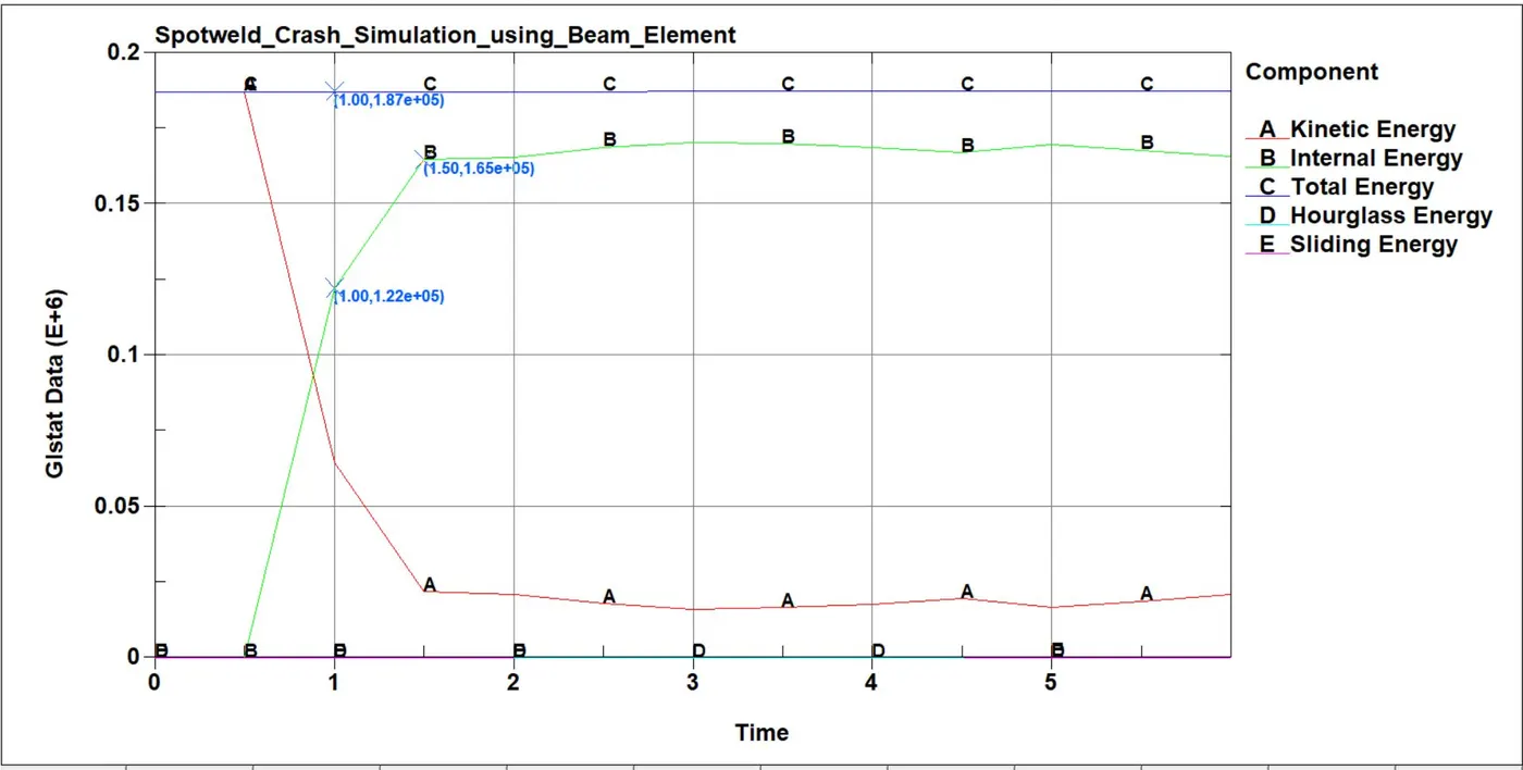
Fig 13:- Conservation of energies in beam element spotweld model
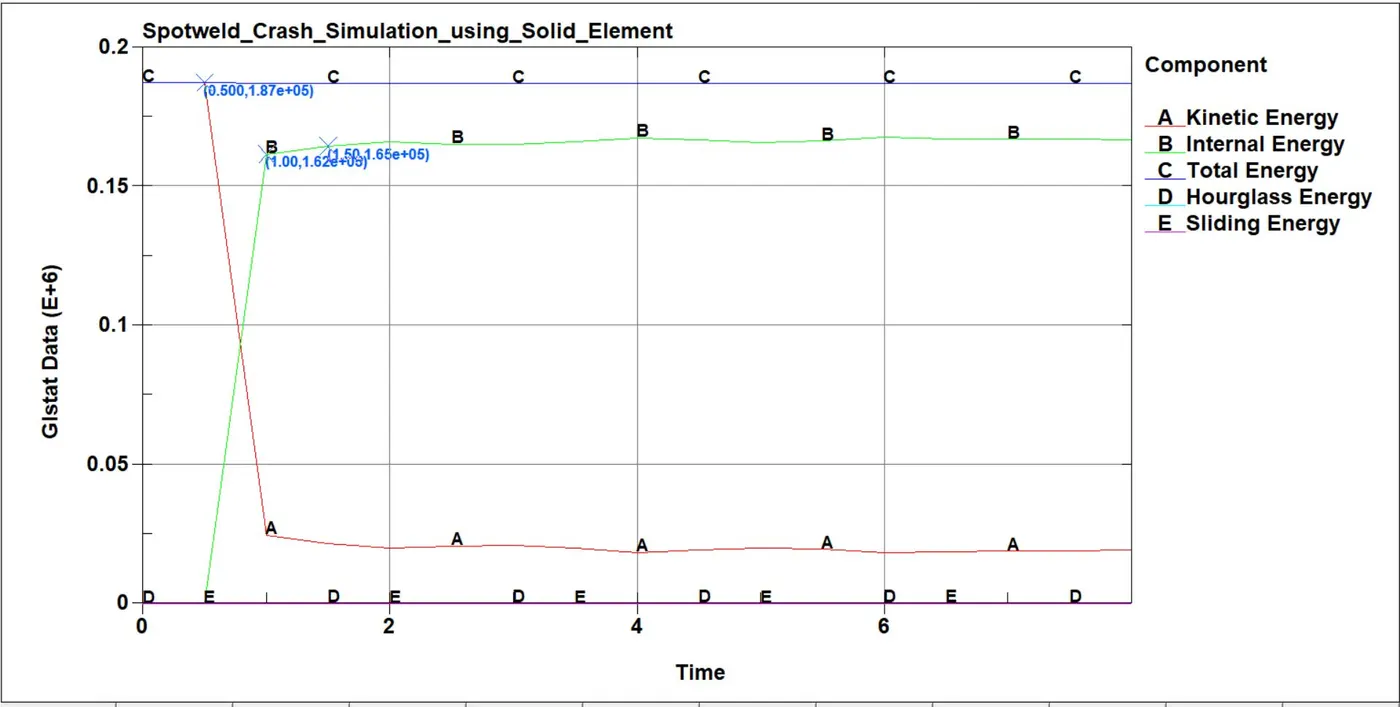
Fig 14:- Conservation of energies in solid element spotweld model
Fig. 13 and 14 are showing the result of the energies conservation of the model using beam spotweld and solid spotweld in which the total energy is the same. The value of Hourglass energy is very small as compared to internal energy in both cases. The fluctuation of energy during collision is more in the model with beam element spotweld as compared to solid element spotweld.
7.5 Axial Forces- It is the forces generated in the spotweld element in the simulation. It started with the collision and ended with when the element gets failed.
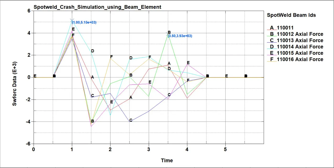
Fig 15:- Axial forces in Model with beam element spotweld
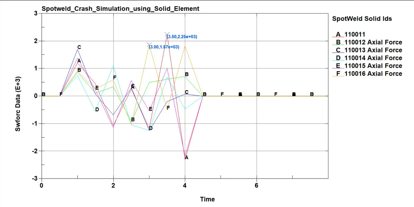
Fig 16:- Axial forces in Model with solid element spotweld
Figure 15 shows the fluctuation of axial force in the model with beam element spotweld and the maximum axial force is generated about 5.15kN which is less as compared to the model with solid element spotweld. In figure 16, the fluctuation of the axial force is smooth as compared to figure 15. In both cases, spotweld located at the side experiencing high axial force.
7.6 Shear Forces -
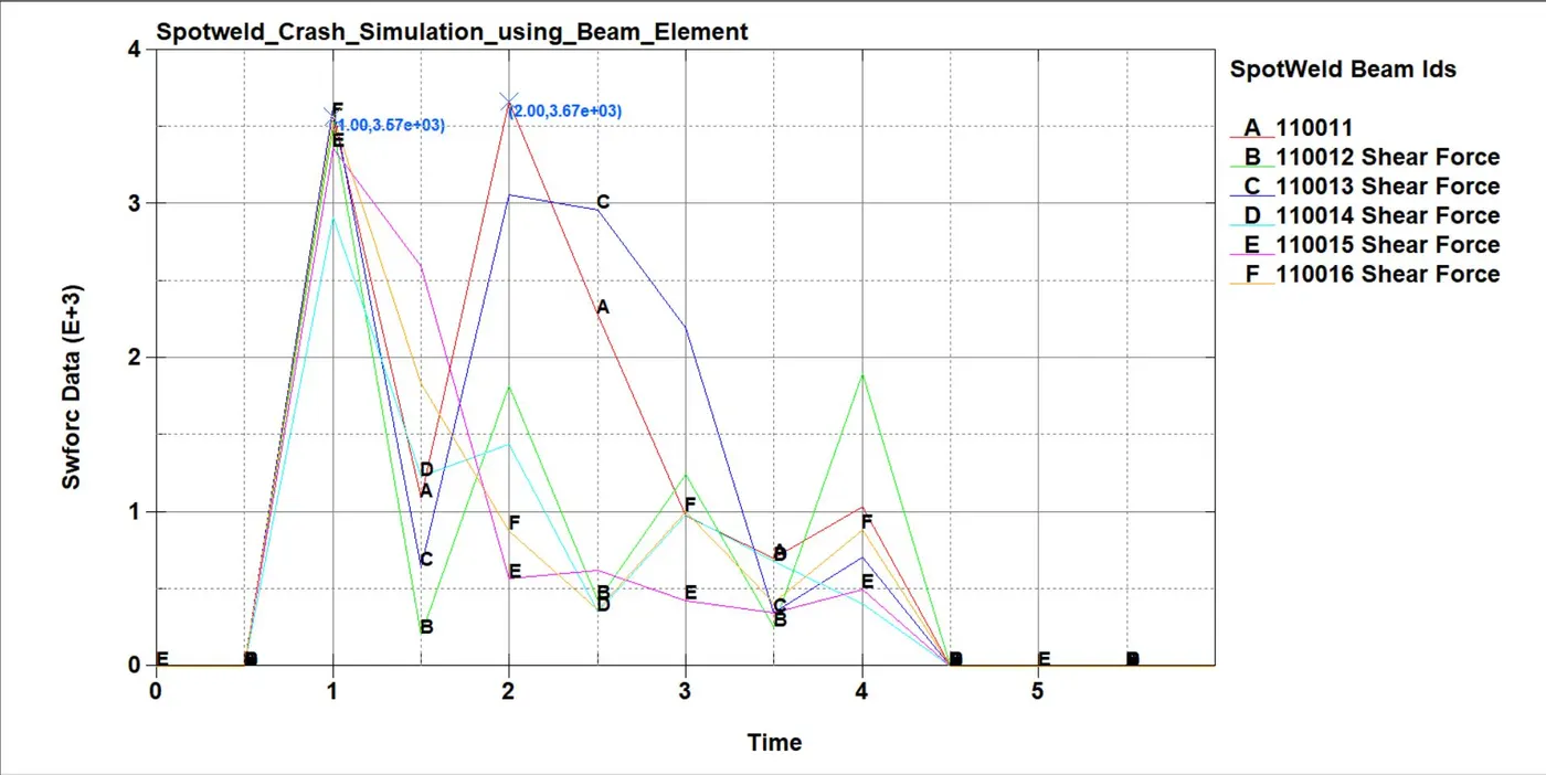
Fig 17:- Shear forces in Model with beam element spotweld
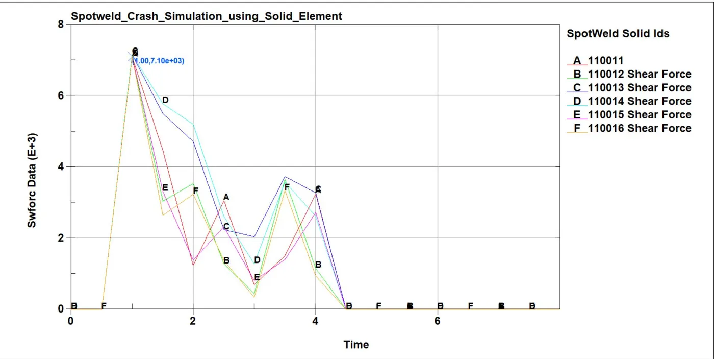
Fig 17:- Shear forces in Model with beam element spotweld
Shear forces generated in the model with beam element is 3.67kN whereas in the solid element is 7.10kN.
Conclusion- From the above simulation, we can conclude that the model with beam element spotweld subjected to high effective stresses as compared to the model with a solid element model. The beam element fails at less axial and shear forces. The energy of both models is nearly the same.