Week-6 Calculate the Stretch Ratio by comparing the ELFORM (-2,-1,1,2) with Ogden_Material Model.
AIM :
Create a block of 10mmx10mmx10mm dimension with 10 elements for each direction and use the material card attached (Ogden_Material.k) that is representative of the material properties. Use appropriate boundary conditions to simulate tensile behavior for the model and finally compare the results from your simulation to the plot above up to stretch ratio 5. Only the uniaxial plot is to be compared. Compare the results for the simulation using ELFORM = 1, 2, -1, -2. The unit of µ in the material definition is in MPa and α is a dimensionless quantity. Modify those quantities according to your unit systems. Use a proper solver (Implicit/Explicit) and also explain the reason.
DELIVERABLES :
- An excel sheet with proper conversion and calculation of Stress/Strain and the Stretch Ratio for all the ELFORM.
- A proper image of the plot comparison of various ELFORMS against the Uniaxial Plot given in the challenge.
THEORY :
All the engineering problems are categorized into time scale of physics. Fast process are time dependent where inertial effects can not be neglected like in dynamic analysis so explicit analysis is better option for this where it is conditionally stable and it handles non linearities with ease. whereas in slow process where time is not so important where loads are applied slowly and inertial effects are neglected like in static and quasi static analysis so it is better to use implicit analysis.
The tensile behavior of cube is time independent and a slow process. The inertial effects are also not important here. So, the implicit method is the best choice for the given problem. The material used for the model is ogden rubber material. This has a non linear stress-strain behavior and ao cannot be solved in one step but equilibrium iterations would be used to solve this problem.
ELFORM-2: fully integrated S/R solid intended for elements with poor aspect ratio, accurate formulation and require higher computational cost than ELFORM-1
ELFORM-1: fully integrated S/R solid intended for elements with poor aspect ratio, efficient formulation.
ELFORM1: constant stress solid element (default). It requires hourglass control for large deformation problems due to under integrated formulation.
ELFORM2: fully integrated S/R solid.
Procedure :
- First we need to create the model of 10mm*10mm*10mm dimension with 10 elements for each direction
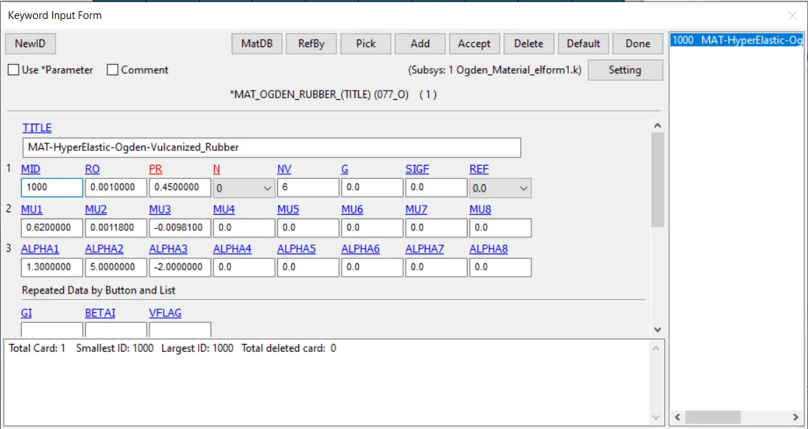
- MATERIAL :
As the material is already given i.e, 077_O -Ogden rubber material where it is hyperelastic material model used to define the materials like rubber and polymers.
- SECTION :
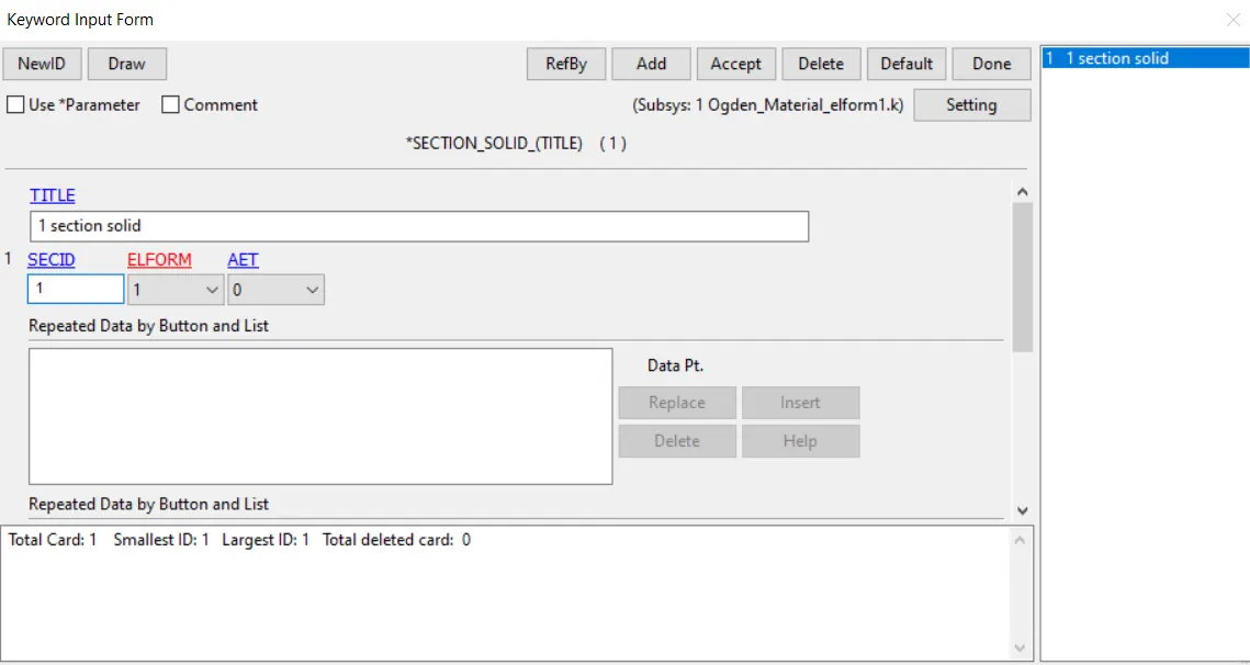
As the given model is solid component so section solid option is choosen and giving the element formulation and defining the section.
- PART :
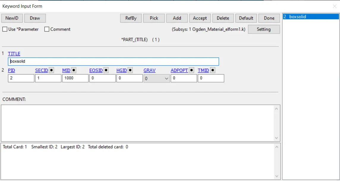
Assigning the section and material to the part.
- CONTROL - TERMINATION:
Giving the end time value.
- CONTROL_IMPLICIT_AUTO
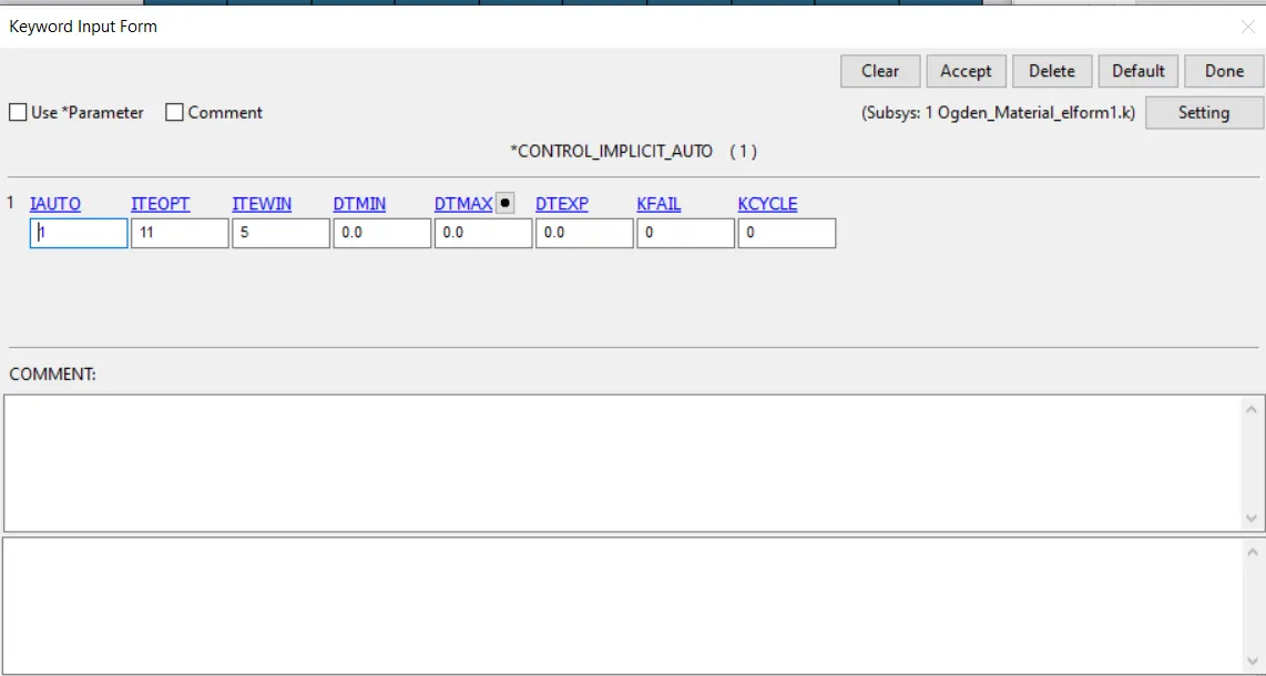
To automatically adjust the time step whenever the iterations are high and low by that timestep can reduce or incresesd within the range of ITEOPT and ITEWIN.
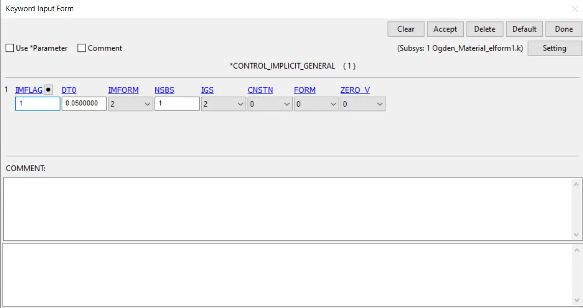
- CONTROL_IMPIICIT_GENERAL
Changing the value of IMFLAG TO 1 to activate the implicit analysis.
- NODE LIST
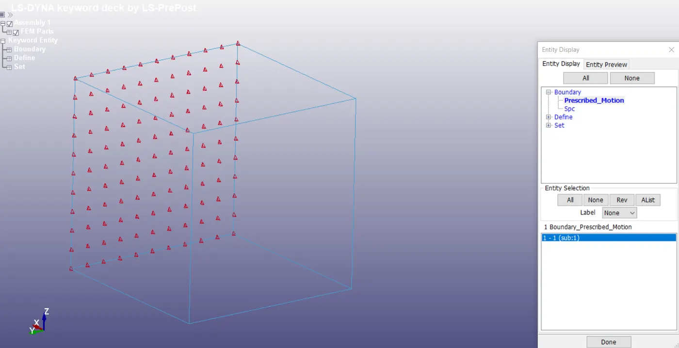
Using the create entity > set data > set node. Creating the set of nodes for constraining and load applying node set are created as shown in the figure.
- BOUNDARY_SPC_SET
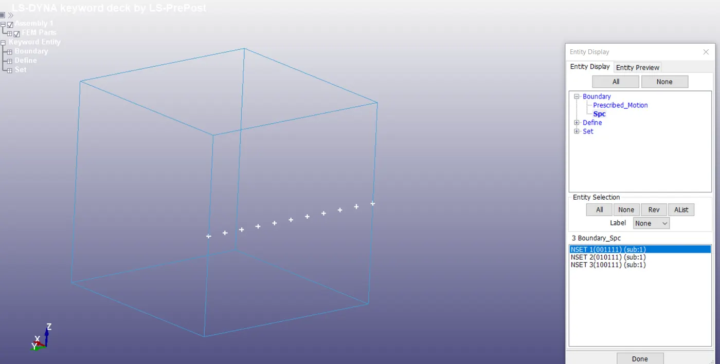
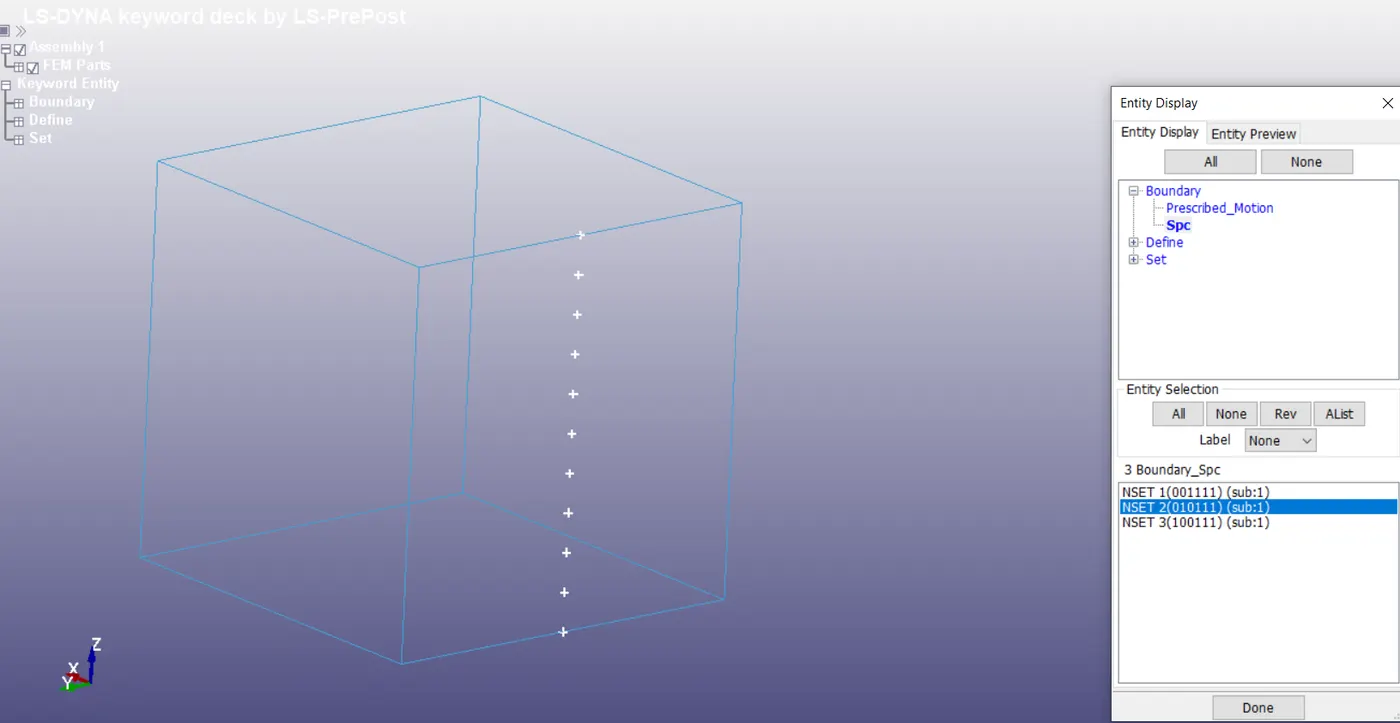
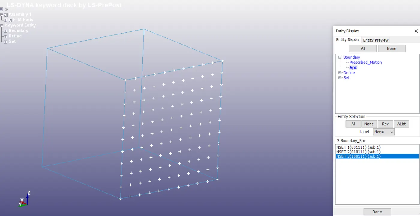
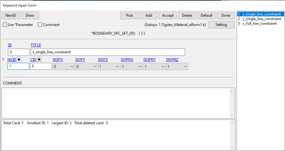
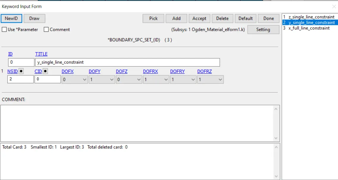
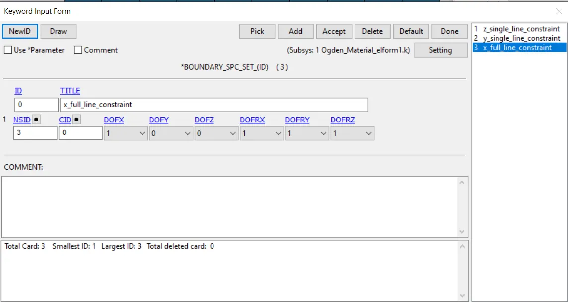
In this we are constraining in all the direction like in X direction we select whole nodes of one side and constraining only in X translational and XYZ rotational. And in Y direction we select only middle line nodes as shown in the figure and giving Y translational constraint and same as in Z direction as Y.
- BOUNDARY_PRESCRIBED_MOTION_SET
Selecting the node set as shown in figure and applying the load applied direction and giving the load curve id.
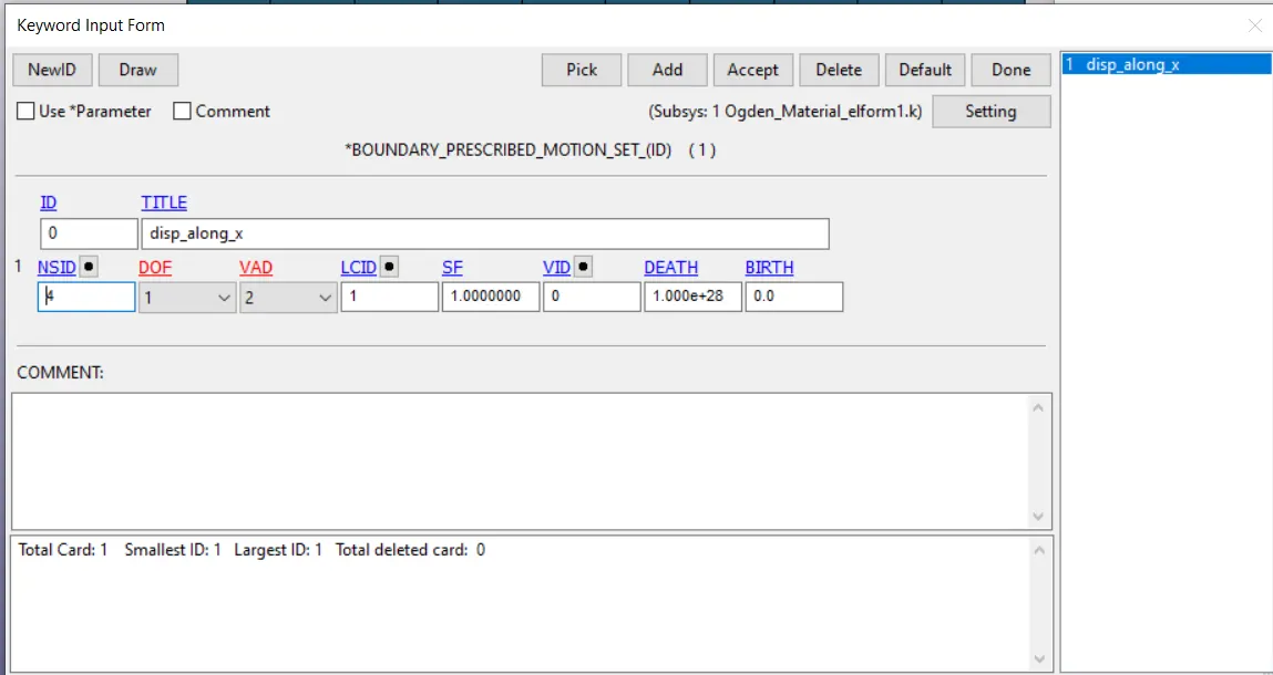
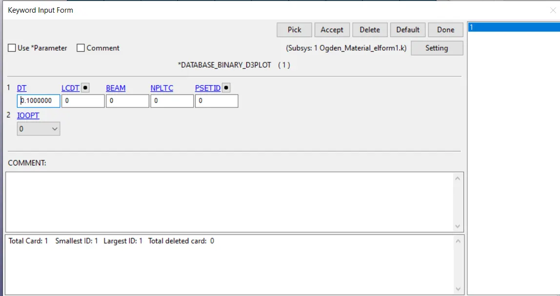
- DATABASE _ BINARY_D3PLOT
Giving the dt (time step) value to 0.1
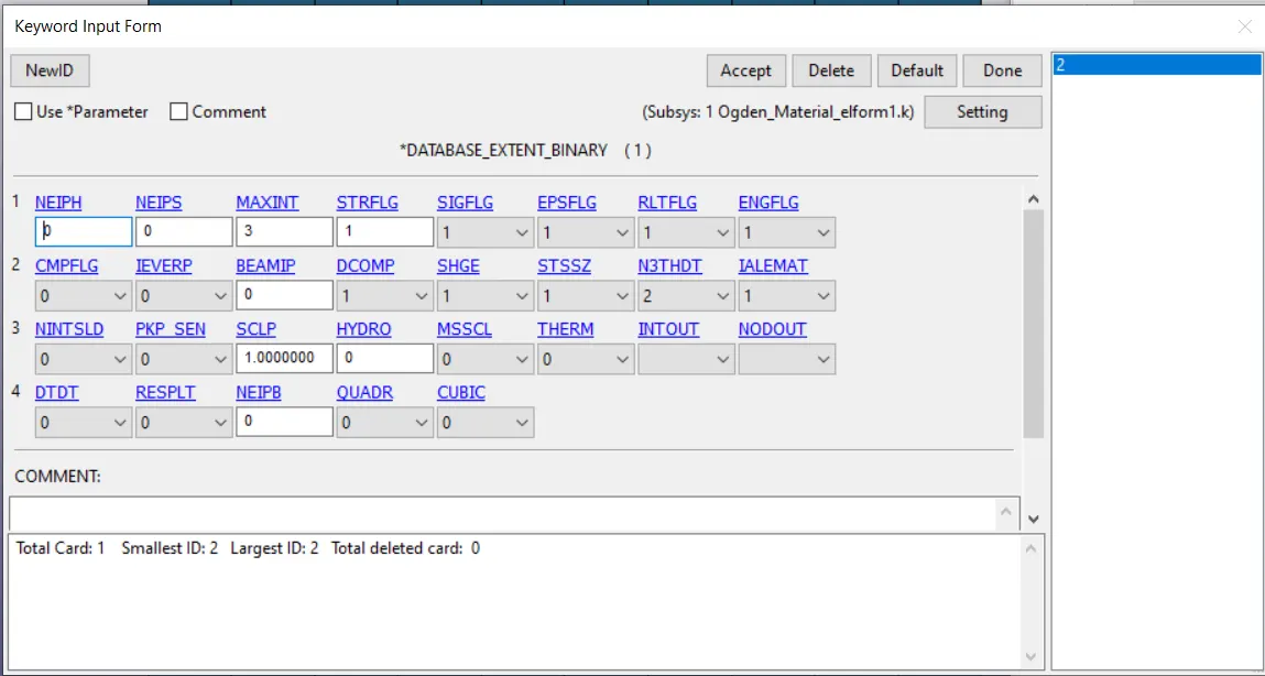
- DATABASE_ EXTENT_BINARY
Just changing the value of STRFLG to 1 to get the value of strains.
- we get the output of stress and strain in the form of true stress and true strain but we want engineering stress and strain to plot the graph so this can be done through the following equtions
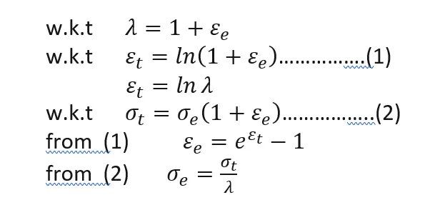
where, = stretch ratio
= True strain
= true stress
= Engineering strain
= Engineering stress
RESULTS:
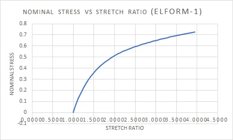
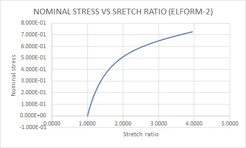
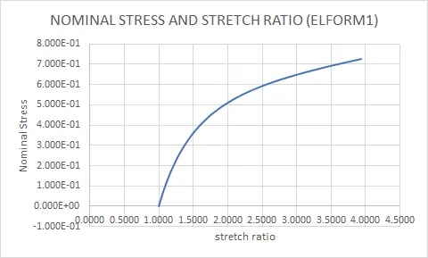
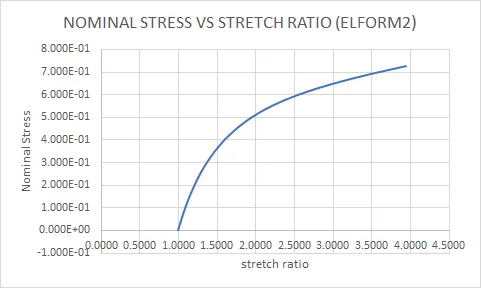
So from the above figures we can observe all the element formulation givrn almost same graph with slight change in some values that too in the 3rd or 4th decimal value so that doesn't make any much changes other important aspects to observe is computational time where elform1 takes least compared to elform2 and elform-1 takes least compared to elform-2 and the excel sheet is attached in the report.
CONCLUSION:
The model is built according to the given data and solver deck is prepared as shown in the procedure. The graph of Nominal stress vs Stretch ratio is plotted for different element formulation. There is no significant variation in the final result.