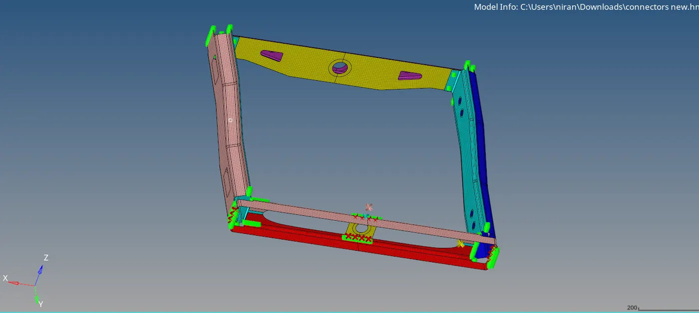
Making the connections for frame assembly using Hypermesh
https://drive.google.com/drive/folders/1InXOXSdzpE52_tLNinYBZuSLIL_GMiVI?usp=sharing
OBJECTIVE: to create the connectors and attach the various parts of the given model.
- Right_Rail_2 & Front_truss_1 - Seam-Quad(angled+capped+L).
- Left_Rail_2 & Front_truss_1 - Quad elements.
- Front_truss_2, Front_truss_1 & Right_Rail_1 - Spot weld with 3 Layers and 5 mm Diameter.
- Front_truss_2, Front_truss_1 & Left_Rail_1 - Hexa (Adhesive).
- Rear_truss_2 & Right_Rail_2 - Bolt Connector.
- Rear_truss_2 & Left_Rail_2 - Bolt Connector.
- Right_Rail_1 & Right_Rail_2 - Spot-weld with Rigid Elements.
- Left_Rail_1 & Left_Rail_2 - Spot-weld withSpring Elements.
- Rest all the component left Join them with suitable connectors.
PROCEDURE:
- Importing the geometry
- As there is no solid surface and need to geometry clean up of the given model so directly going for mesh
- 2D mesh is created using the automesh option of mesh size 6mm
- Clearing the tria elements and then model is ready for connecting the components.
- (i) right rail 2 & Front truss 1 – Connectors > seam > Quad(angled+capped+L), selecting the node list, components and giving the tolerance, weld angle values and then creating the link.
- (ii) Left rail 2 & Front truss 1 – Connectors > seam > Quads, selecting the node list, components and giving the tolerance value and creating the link.
- (iii) Front truss 2, Front truss 1 & Right rail 1 – Connectors > spot > weld, selecting the nodes, components and giving 3 layers and 5mm diameter and then creating the link.
- (iv) Front truss 2, Front truss 1 & Left rail 1 – Connectors > seam > hexa(adhesive), selecting the nodes, components and giving the tolerance, stripes, coats and width. Creating the link.
- (v) Rear truss 2 & Right rail 2 – Connectors > bolt > bolt(general), selecting the nodes, components and giving the tolerance, selecting the create hole, if none. Creating the link.
- (vi) Rear truss 2 & Left rail 2 – Connectors > bolt > bolt(general), selecting the nodes, components and tolerance. Creating the link.
- (vii) Right rail 1 & Right rail 2 – Connectors > spot > rigid, selecting the nodes, components, tolerance and diameter value. Creating the link.
- (viii) Left rail 1 & Left rail 2 – Connectors > spot > spring, selecting the nodes, components, tolerance and diameter value. Creating the link.
- (ix) connecting the all components with suitable links.
CONCLUSION:
As by given objective all the components are connected with suitable link.