Week-6 Calculate the Stretch Ratio by comparing the ELFORM (-2,-1,1,2) with Ogden_Material Model.
AIM:
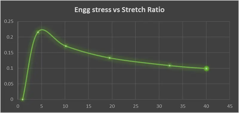
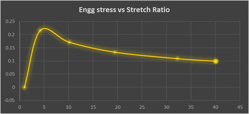
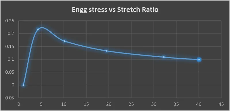
Create a 10x10x10mm solid mesh and run a pure tensile run on it with stretch ratio of 5. Compare different element formulations of solids 1,-1,2,-2 and plot engineering stress vs stretch values. The given is a Ogden material card which is hyperelastic (rubber).
EXPLANATION:
Element formulations used are 1,-1,2,-2 for solids.
ELFORM 1 - underintegrated constant stress ; needs hourglass stabilisation; efficient and accurate
ELFORM 2 - Reduced integrated ; no hour glass stabilisation needed; slower than ELFORM 1; shear locking can occur
ELFORM(-1 )- Similiar to ELFORM 2 , but shearlocking is accounted for; efficient formulation (CPU time)
ELFORM (-2) - Similiar to -1 , more accurate, more computational cost.
PROCEDURE:
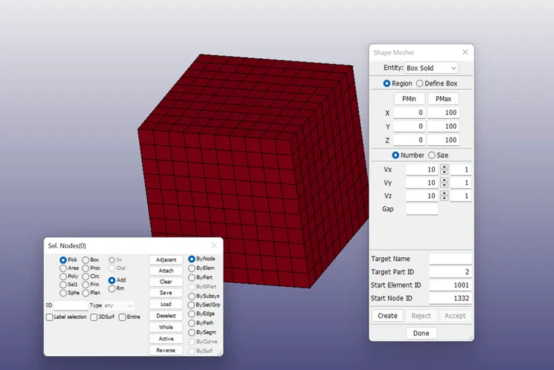
1. Import the Ogden.k key file into the LS Dyna. create the cube of size 10mm X 10mm X 10mm.
2. To create section card from keyword>>all>>section>>solid>>here we will input id, elform type.
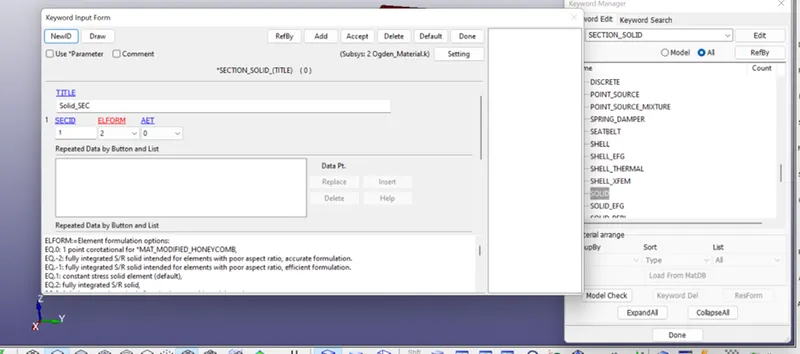
As per given cases we have to change ELFORM as 1, -1 & -2, accordingly as shown in above snap or we can do it form .k file after saving it.
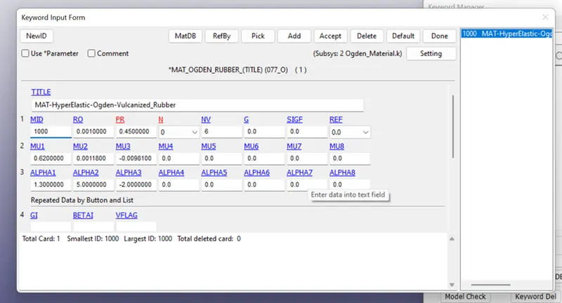
3. we will check the MAT card given to us.
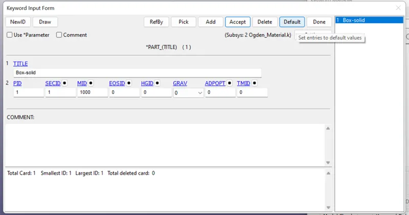
4. Finally we have to assign the section and material to the part.
5. To fix the Bottom face, we will use different set of nodes and using single point constraint boundary, we can allow or constraint the nodes with different degrees of freedom.
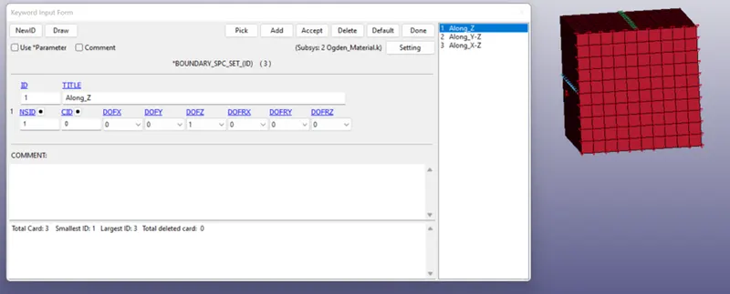
Here we will fix the Bottom of the Cube and give the motion to the set of nodes on the Upper face.
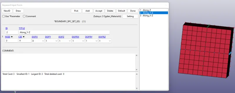
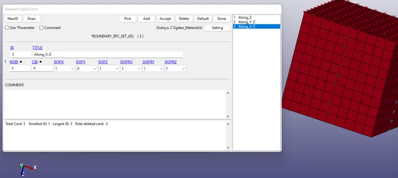
Here constraints are given for the different set of nodes in a way that cube can shrink in X and Y direction upon tension in Z-Direction and also stick to its position. This boundary condition can be relatable to the real-time boundary condition.
6. To apply the tensile load in Z-Direction to the cube, we have to give the motion to the set of node on the upper face of the cube.
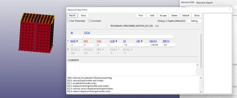
Here, we have given DOF = 3 to allow translation in Z-Direction translation and VAD = 2 is given for Displacement.
7. Then define curve for displacement is given below, displacement is linearly applied at constat rate.
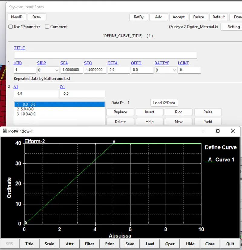
8. This is the nonlinear implicit analysis, we need to create some implicit cards to activate implicit method like implicit auto, implicit general etc.
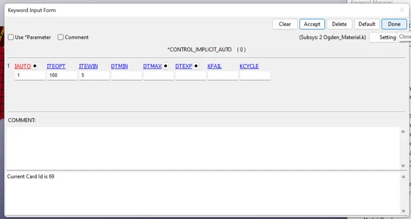
- In *CONTROL_IMPLICIT_AUTO, values of DTMIN and DTMAX are not defined, so that the solver can change the time step size as needed automatically.
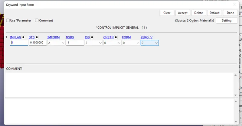
- In *CONTOL_IMPLICIT_GENERAL, IMFLAG =1 is given to activate the implicit analysis method and initial Time step value is given as 0.1.
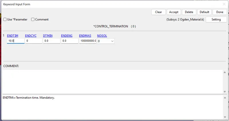
- In CONTROL_TERINATION, ENDTIM is set to 10. Here termination does not represent the time but gives the value at which step the analysis will end.
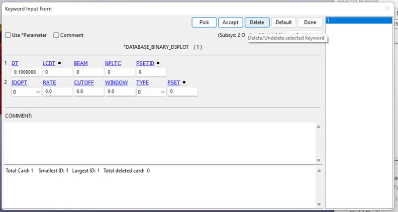
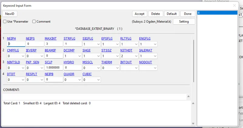
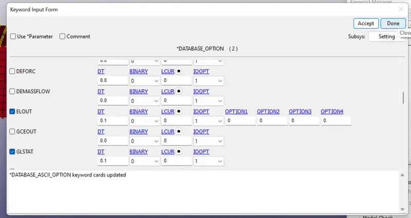
9. Now we will provide database output parameters to get the required results as d3plot and ascii plot files.
10. Check the model by model checker and Run the file get the simulation.
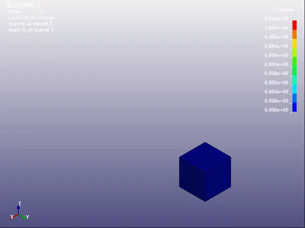
ELFORM:1
ELFORM:2
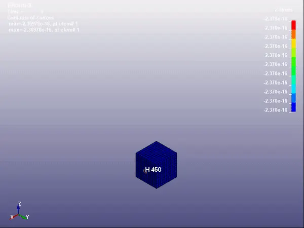
ELFORM:-1
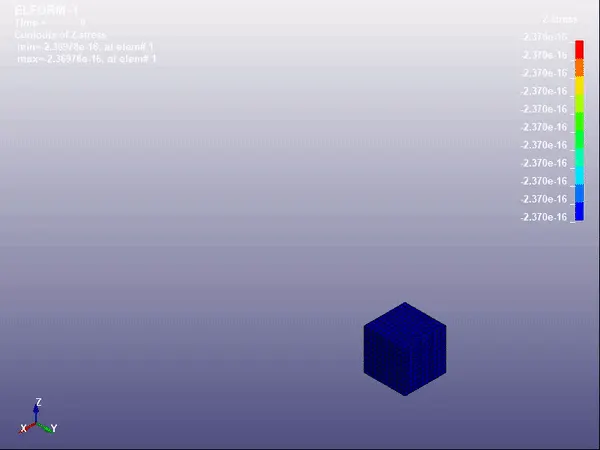
ELFORM:-2
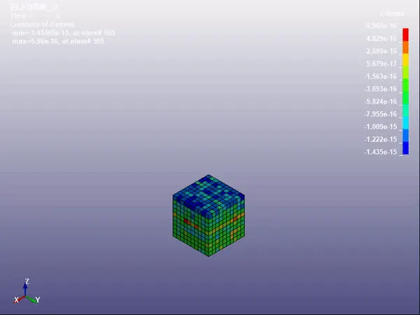
- Maximum stress we obtain is 4 Mpa along the Z-direction. As the tension is applied in Z-direction.
- We can observe the same value of maximum stress for all cases, but the distribution of stress is different in all cases.
FORMULA:
Engineering and True stress/ strain relations before the necking process.
λ: Stretch ratio
ε: Engineering strain
ε*: True strain
σ: Engineering stress
σ*: True stress
Relation between True stress and Engineering stress (Before necking in tensile loading)
σ* = σ(1 + ε)
so, σ = σ* / (1 + ε)
Relation between True strain and Engineering strain (Before necking in tensile loading)
ε* = ln (1 + ε)
So, e^(ε*) - 1 = ε
where, 1 + ε = λ
True strain = change in length/ instanteneous length.
Engineering strain = change in length/ origional length.
True stress/strain is experimental stress/strain.
Engieering stress/ strain is theoritical stress/strain.
Stretch ratio (λ):
λ : Stretch ratio
δl : change in length
l : Final length
ε: Engineering strain
l* : origional length = 10mm
D: displacement
T: time step in ms
Engineering strain is defined as,
ε = δl/l*
Stretch ratio is defined as,
λ = 1 + ε
CASE : 1
| ELFORM 2 | |||||
| TIME | TRUE STRAIN | TRUE STRESS | ENGG stress | ENGG strain | Stretch ratio |
| 0.00E+00 | 0.00E+00 | -2.37E-16 | -2.37E-16 | 0.00E+00 | 1.00E+00 |
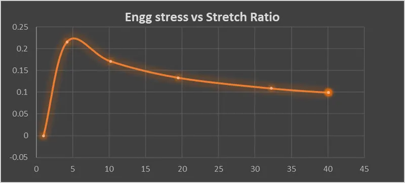
| 1.11E+00 | 6.27E-01 | 9.15E-01 | 2.16E-01 | 3.24E+00 | 4.24E+00 |
| 2.22E+00 | 1.01E+00 | 1.74E+00 | 1.71E-01 | 9.18E+00 | 1.02E+01 |
| 3.33E+00 | 1.29E+00 | 2.59E+00 | 1.33E-01 | 1.85E+01 | 1.95E+01 |
| 4.44E+00 | 1.51E+00 | 3.50E+00 | 1.09E-01 | 3.12E+01 | 3.22E+01 |
| 5.56E+00 | 1.60E+00 | 3.97E+00 | 9.91E-02 | 3.91E+01 | 4.01E+01 |
| 6.67E+00 | 1.60E+00 | 3.97E+00 | 9.91E-02 | 3.91E+01 | 4.01E+01 |
| 7.78E+00 | 1.60E+00 | 3.97E+00 | 9.91E-02 | 3.91E+01 | 4.01E+01 |
| 8.89E+00 | 1.60E+00 | 3.97E+00 | 9.91E-02 | 3.91E+01 | 4.01E+01 |
| 1.00E+01 | 1.60E+00 | 3.97E+00 | 9.91E-02 | 3.91E+01 | 4.01E+01 |
CASE: 2
| ELFORM 1 | |||||
| TIME | TRUE STRAIN | TRUE STRESS | ENGG stress | ENGG strain | Stretch ratio |
| 0.00E+00 | 0.00E+00 | 0.00E+00 | 0.00E+00 | 0.00E+00 | 1.00E+00 |
| 1.11E+00 | 6.27E-01 | 9.15E-01 | 2.16E-01 | 3.24E+00 | 4.24E+00 |
| 2.22E+00 | 1.01E+00 | 1.74E+00 | 1.71E-01 | 9.18E+00 | 1.02E+01 |
| 3.33E+00 | 1.29E+00 | 2.59E+00 | 1.33E-01 | 1.85E+01 | 1.95E+01 |
| 4.44E+00 | 1.51E+00 | 3.50E+00 | 1.09E-01 | 3.12E+01 | 3.22E+01 |
| 5.56E+00 | 1.60E+00 | 3.97E+00 | 9.92E-02 | 3.90E+01 | 4.00E+01 |
| 6.67E+00 | 1.60E+00 | 3.97E+00 | 9.91E-02 | 3.91E+01 | 4.01E+01 |
| 7.78E+00 | 1.60E+00 | 3.97E+00 | 9.91E-02 | 3.91E+01 | 4.01E+01 |
| 8.89E+00 | 1.60E+00 | 3.97E+00 | 9.91E-02 | 3.91E+01 | 4.01E+01 |
| 1.00E+01 | 1.60E+00 | 3.97E+00 | 9.91E-02 | 3.91E+01 | 4.01E+01 |
CASE: 3
| ELFORM -1 | |||||
| TIME | TRUE STRAIN | TRUE STRESS | ENGG stress | ENGG strain | Stretch ratio |
| 0.00E+00 | 0.00E+00 | -2.37E-16 | -2.37E-16 | 0.00E+00 | 1.00E+00 |
| 1.11E+00 | 6.27E-01 | 9.15E-01 | 2.16E-01 | 3.24E+00 | 4.24E+00 |
| 2.22E+00 | 1.01E+00 | 1.74E+00 | 1.71E-01 | 9.18E+00 | 1.02E+01 |
| 3.33E+00 | 1.29E+00 | 2.59E+00 | 1.33E-01 | 1.85E+01 | 1.95E+01 |
| 4.44E+00 | 1.51E+00 | 3.50E+00 | 1.09E-01 | 3.12E+01 | 3.22E+01 |
| 5.56E+00 | 1.60E+00 | 3.97E+00 | 9.91E-02 | 3.91E+01 | 4.01E+01 |
| 6.67E+00 | 1.60E+00 | 3.97E+00 | 9.91E-02 | 3.91E+01 | 4.01E+01 |
| 7.78E+00 | 1.60E+00 | 3.97E+00 | 9.91E-02 | 3.91E+01 | 4.01E+01 |
| 8.89E+00 | 1.60E+00 | 3.97E+00 | 9.91E-02 | 3.91E+01 | 4.01E+01 |
| 1.00E+01 | 1.60E+00 | 3.97E+00 | 9.91E-02 | 3.91E+01 | 4.01E+01 |
CASE: 4
| ELFORM -2 | |||||
| TIME | TRUE STRAIN | TRUE STRESS | ENGG stress | ENGG strain | Stretch ratio |
| 0.00E+00 | 0.00E+00 | -7.53E-16 | -7.53E-16 | 0.00E+00 | 1.00E+00 |
| 1.11E+00 | 6.27E-01 | 9.15E-01 | 2.16E-01 | 3.24E+00 | 4.24E+00 |
| 2.22E+00 | 1.01E+00 | 1.74E+00 | 1.71E-01 | 9.18E+00 | 1.02E+01 |
| 3.33E+00 | 1.29E+00 | 2.59E+00 | 1.33E-01 | 1.85E+01 | 1.95E+01 |
| 4.44E+00 | 1.51E+00 | 3.50E+00 | 1.09E-01 | 3.12E+01 | 3.22E+01 |
| 5.56E+00 | 1.60E+00 | 3.97E+00 | 9.91E-02 | 3.91E+01 | 4.01E+01 |
| 6.67E+00 | 1.60E+00 | 3.97E+00 | 9.91E-02 | 3.91E+01 | 4.01E+01 |
| 7.78E+00 | 1.60E+00 | 3.97E+00 | 9.91E-02 | 3.91E+01 | 4.01E+01 |
| 8.89E+00 | 1.60E+00 | 3.97E+00 | 9.91E-02 | 3.91E+01 | 4.01E+01 |
| 1.00E+01 | 1.60E+00 | 3.97E+00 | 9.91E-02 | 3.91E+01 | 4.01E+01 |
RESULT:
A solid block FE element of specified dimensions was created and the provided ogden material was applied to it, after which a uniaxial tensile test was carried out for four cases, each with different element formulations. The analysis was carried out with the help of the implicit solver in LS-Dyna, considering this test is considered quasi-static. The stretch ratio vs uniaxial engineering stress plots were created with the help of the results from the simulations.