Week-6 Calculate the Stretch Ratio by comparing the ELFORM (-2,-1,1,2) with Ogden_Material Model.
Aim: To create a simulation of box made of hyper-elastic material (ogden material card), stress/strain curve is obtained and compared with elform 1,-1,2,-2.
Objective: To create a simulation of the box structure, the simulation with various elform 1,-1,2,-2 and stress/strain curve is obtained to compare the same. The simulation helps understand the stress/strain curve when different elform is used and explain the type of solver whether to use the explicit or implicit solver.
Procedure:
- The given model is downloaded and open in the Ls-dyna software by Ls-prepost.
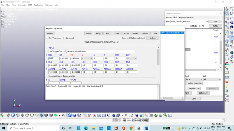
Figure 1: Ogden material card
- The model is given with “gm,mm,ms” dimensions.
- The mesh model is created with “10*10*10” dimension using the shape mesher.
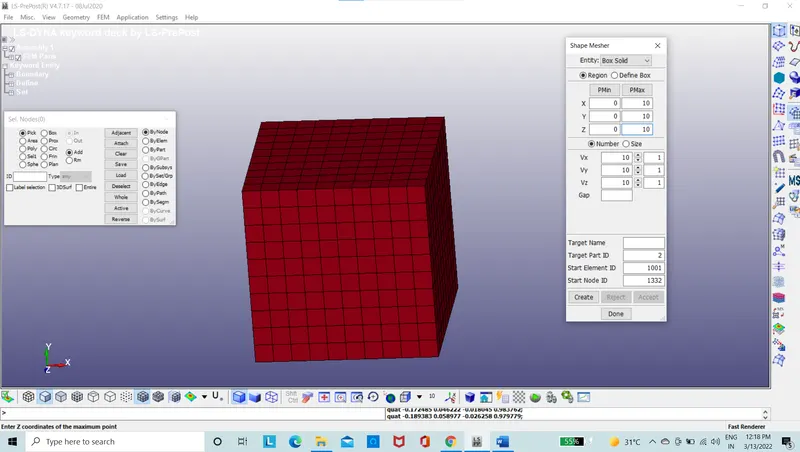
Figure 2: Model with meshed elements
- The section id is created with elform 1 using solid section card.
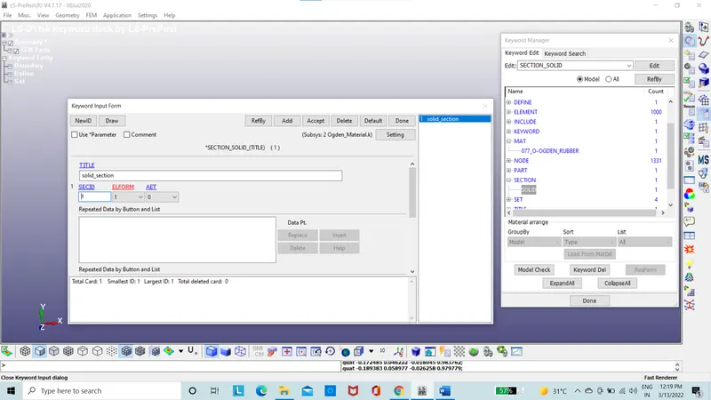
Figure 3: Section id
- The node set was created in order to constrain the model and in Z,Y and ZY are set free in mid node and side nodes where required.
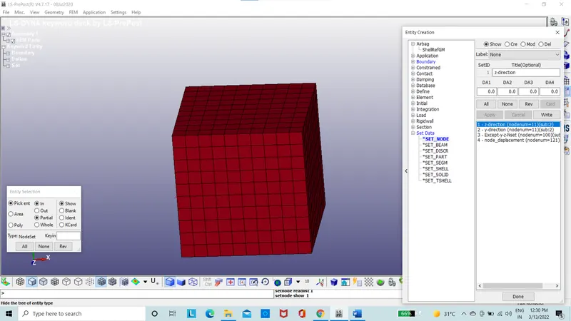
Figure 4: Node set List
- The model is constrained using the Spc boundary set.
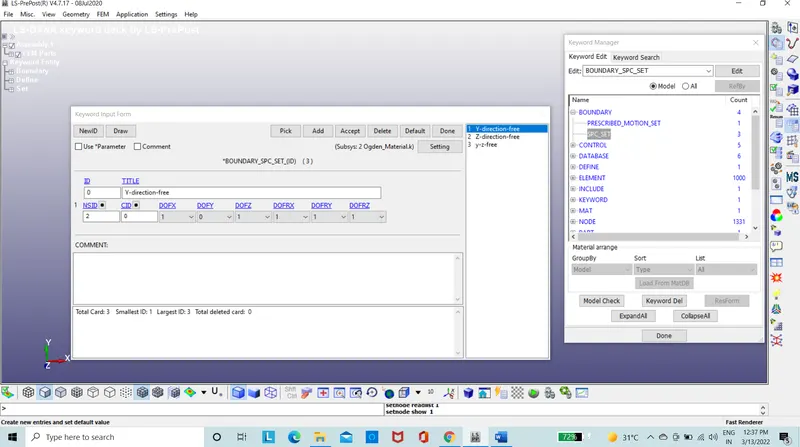
Figure 5: Spc boundary set
- Using the define option, load curve is created.
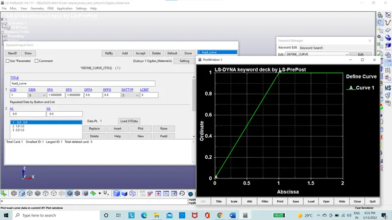
Figure 6: Load curve card
- The displacement is given using the prescribed motion set with Scale factor as 40. Where the stretch ratio is given as 5. Therefore, λ=1+ξ, 5=1+δL/L=1+δL/10, δL=40mm.
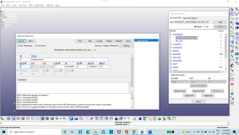
Figure 7: Prescribed motion set card
- Since the load condition is steady, the internal and external forces are balanced, considering this system to be working as implicit analysis. Therefore, the implicit card is used.
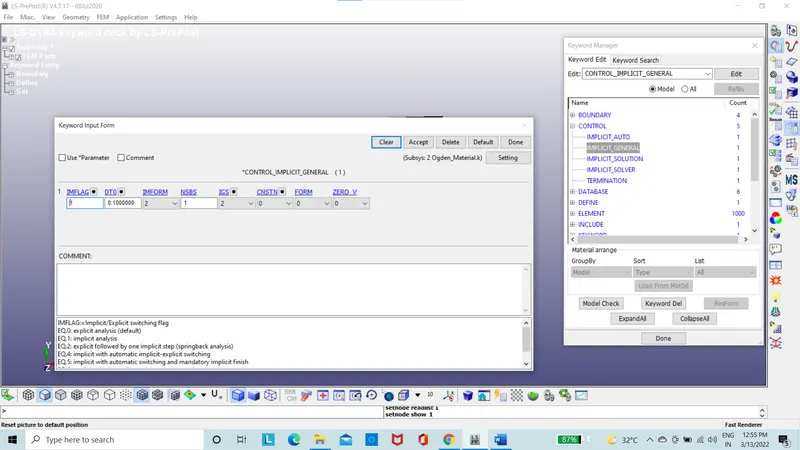
Figure 8: Implicit cards
- The database is set for ASCII with GLSTAT,MATSUM,GLEOUT,RCFORC,SWFORC.
- Binary database as D3 plot.
- The database is set with extent binary with STRFLG set to 1
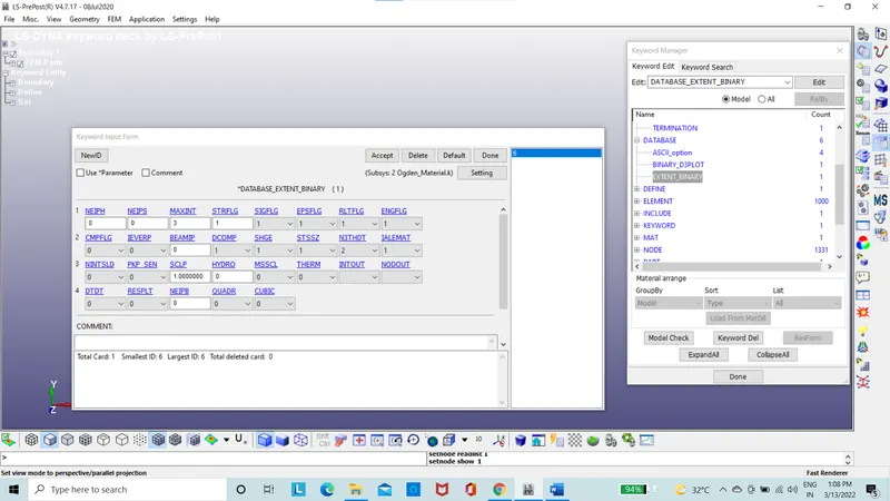
Figure 9: Extent binary card
- The termination time is set as 10.
- The input file is run on Ls-run.
- The command file is run.
- The result file is obtained.
- The result of stress, energies etc are taken into consideration.
- The same procedure is used to create the model with elform -1 in the solid section.
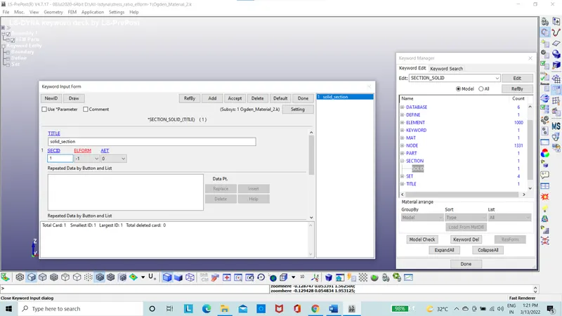
Figure 10: Solid section with Elform -1
- The same procedure is used to create the model with elform 2 in the solid section.
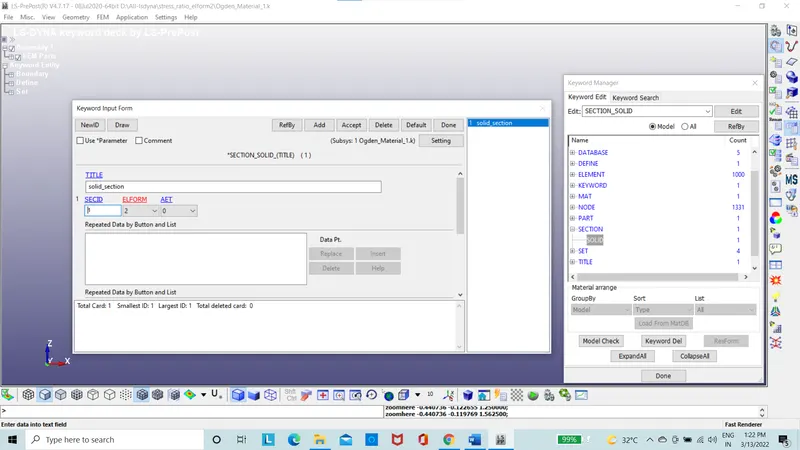
Figure 11: Solid section with Elform 2
- The same procedure is used to create the model with elform -2 in the solid section.
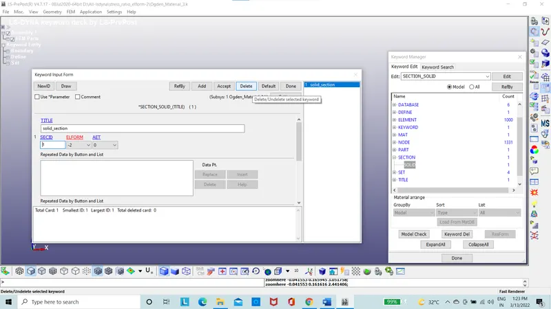
Figure 12: Solid section with Elform -2
- Here, the said stress and strain obtained will be in the form of true stress and strain, which is to be converted to engineering stress and strain using the formula.
True strain = ln*(1+engineering strain)
True stress= engineering stress*(1+engineering strain)
- Thus, using the Excel, need to extract true stress/strain curve and engineering stress/strain curve. Need to compare the engineering curves of different elform.
Results
Case 1: The stress and strain contours for the elform 1 in the direction of X is considered.
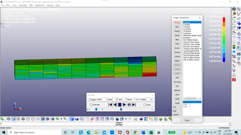
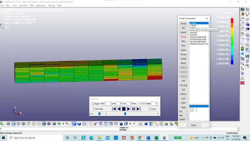
Figure 13: The stress and strain Contours in X-direction for elform 1
Case 2: The stress and strain contours for the elform -1 in the direction of X is considered.
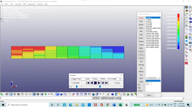
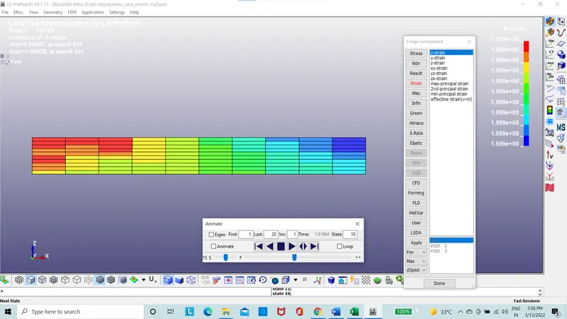
Figure 14: The stress and strain Contours in X-direction for elform -1
Case 3: The stress and strain contours for the elform 2 in the direction of X is considered.

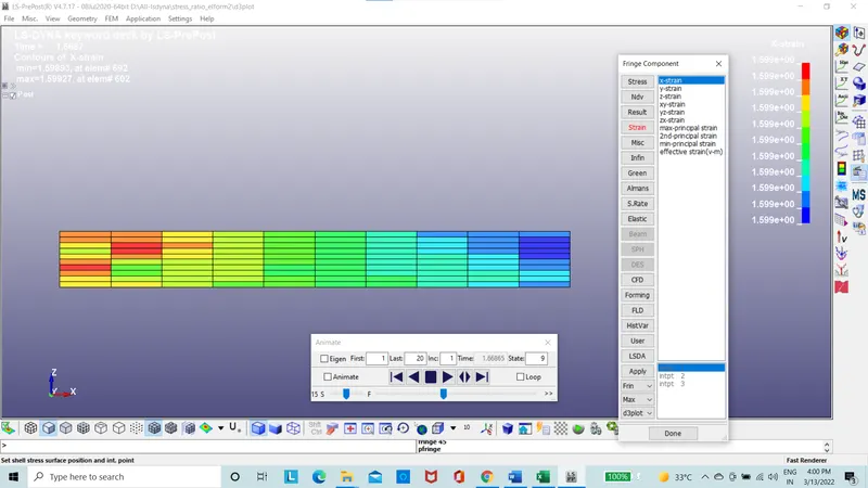
Figure 15: The stress and strain Contours in X-direction for elform 2
Case 4: The stress and strain contours for the elform -2 in the direction of X is considered.
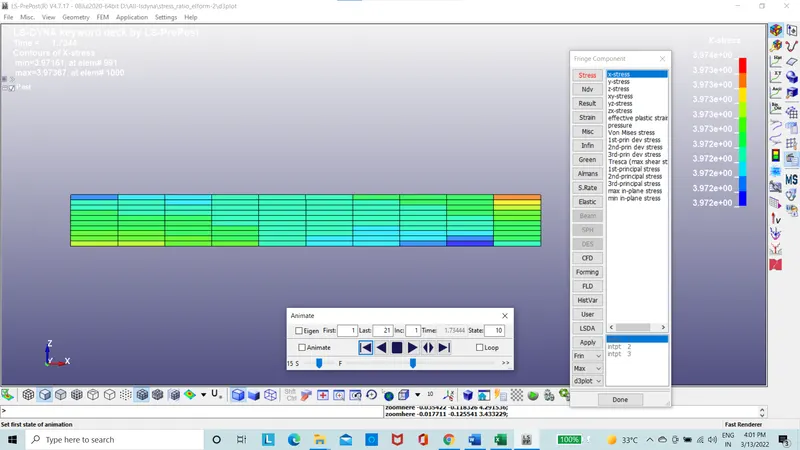
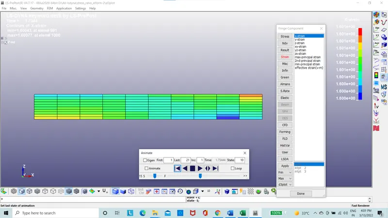
Figure 16: The stress and strain Contours in X-direction for elform 2
From these results, maximum value of stress and strain in the X-direction are same for all elemental formulation and the values are 3.974 Mpa and 1.598 mm respectively.
The true stress and strain curves are plotted and saved in excel sheet and the graph of engineering stress/stretch ratio is plotted, in this the true stress and true strain is converted to engineering stress and strain using the formula:
True strain= ln*(1+Engineering strain)
Engineering strain = Exp(true strain)-1
True stress = engineering stress*(1+Engineering strain)
Engineering stress = True stress/(1+Engineering strain)
Stretch ratio = 1+ (change in length/original length)=1+engineering strain
Case 1: the stress/stretch ratio graph for the elform 1
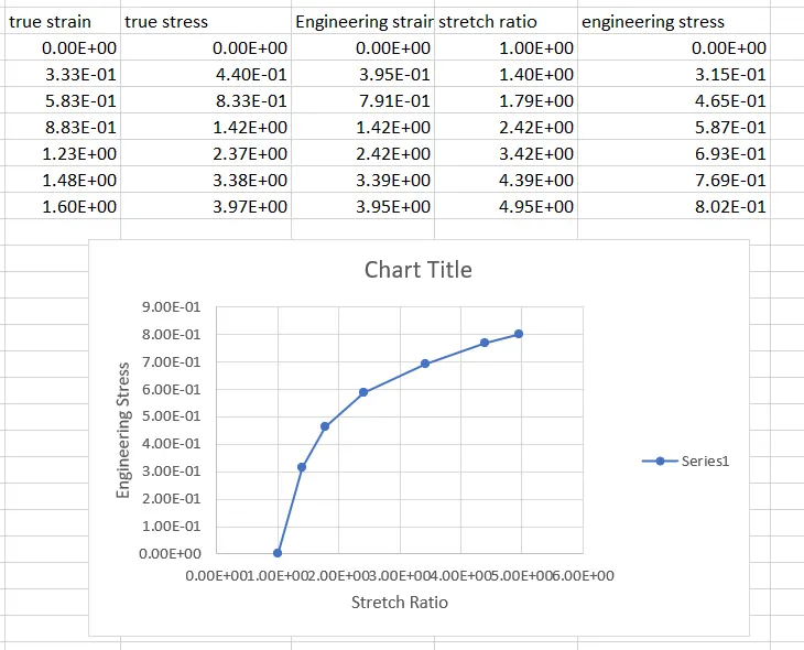
Figure 17: the stress/stretch ratio graph for the elform 1
Case 2: the stress/stretch ratio graph for the elform -1
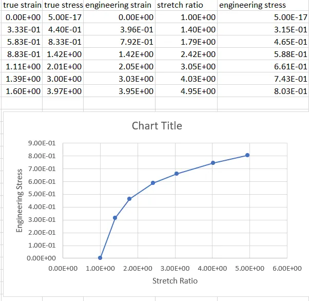
Figure 18: the stress/stretch ratio graph for the elform -1
Case 3: the stress/stretch ratio graph for the elform 2
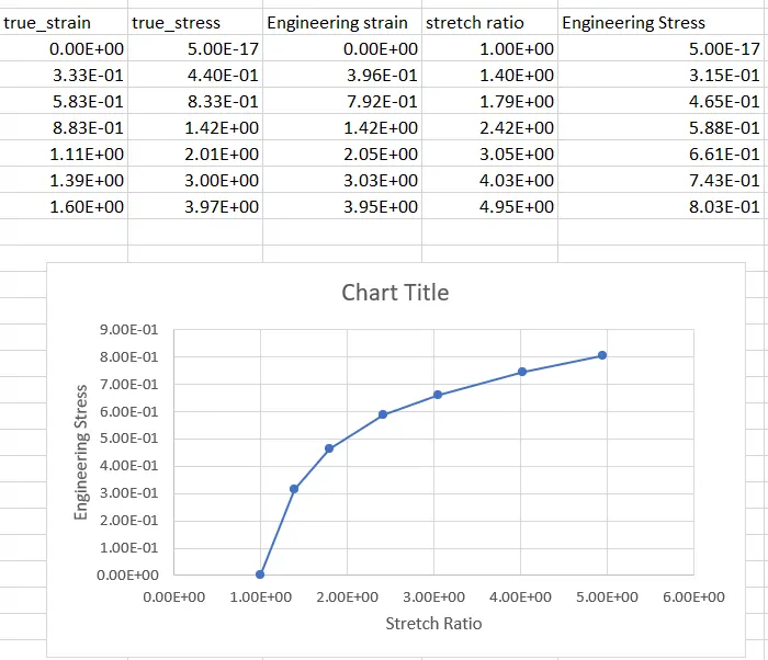
Figure 19: the stress/stretch ratio graph for the elform 2
Case 4: the stress/stretch ratio graph for the elform -2
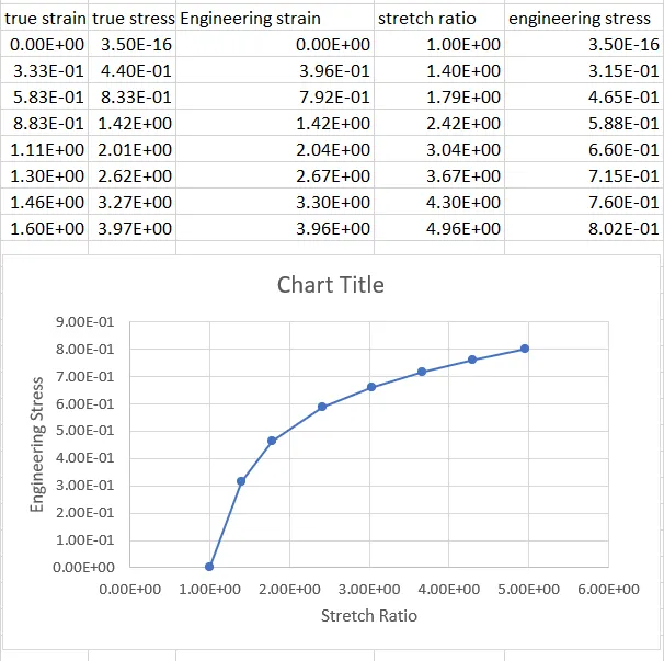
Figure 20: the stress/stretch ratio graph for the elform -2
Form the engineering stress /stretch ratio plots we can conclude that results of the curves observed of elemental formulation 1,-1,2,-2 are of same value.
Conclusion
The implicit analysis is taken into consideration for this project since the internal forces and external forces are balanced and the loading is of steady state with low strain rate acting on the component.
The stress and strain contours are taken in to consideration in the direction of X.
The stress of the component is the element 555 is taken into consideration.
The curve of stress/stretch ratio of elemental formulation 1,-1,2,-2 are of same value.