Week 6
Aim:
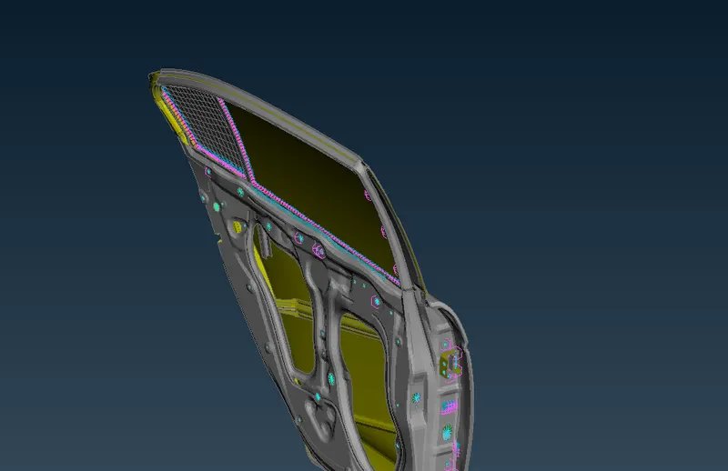
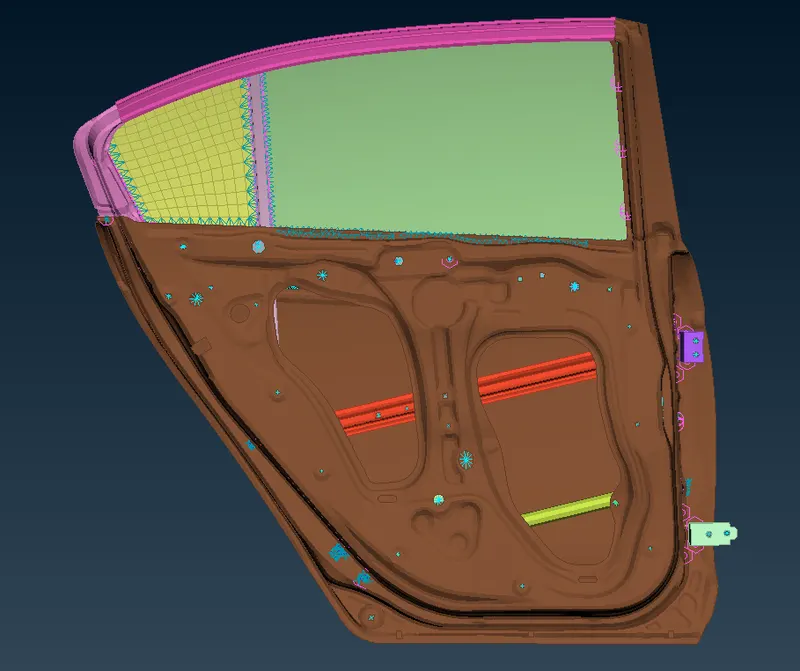
To connect different parts of door assembly using different types of connectors for NVH analysis in the Nastran deck.
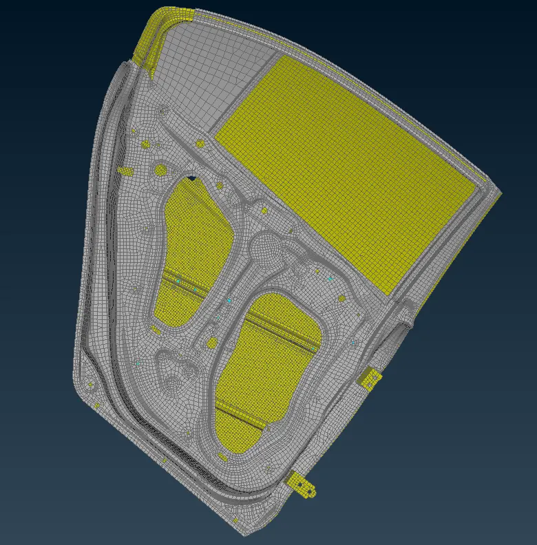
CAD File :
Procedure:
1) Open the Door model
File – Open – Select file – Open.
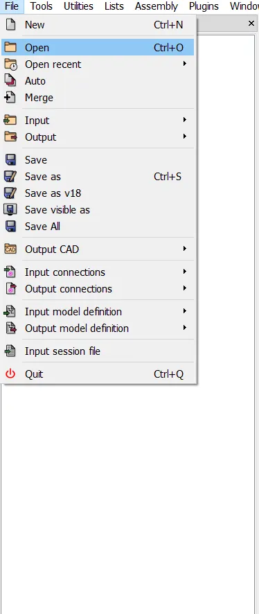
As the model is complex in shape it might take some extra time to open at the initial stage, but once the file is saved in the .ansa extension then the file can be opened in lesser time.
Assign PID to the component
As the model was assigned one PID, this could occur problem while realizing connector, so assigning different PID to a different component. To assign PID sort the surface using not option and PID region option, and assign new PID to extracted surface
Using of !NOT and PID region option

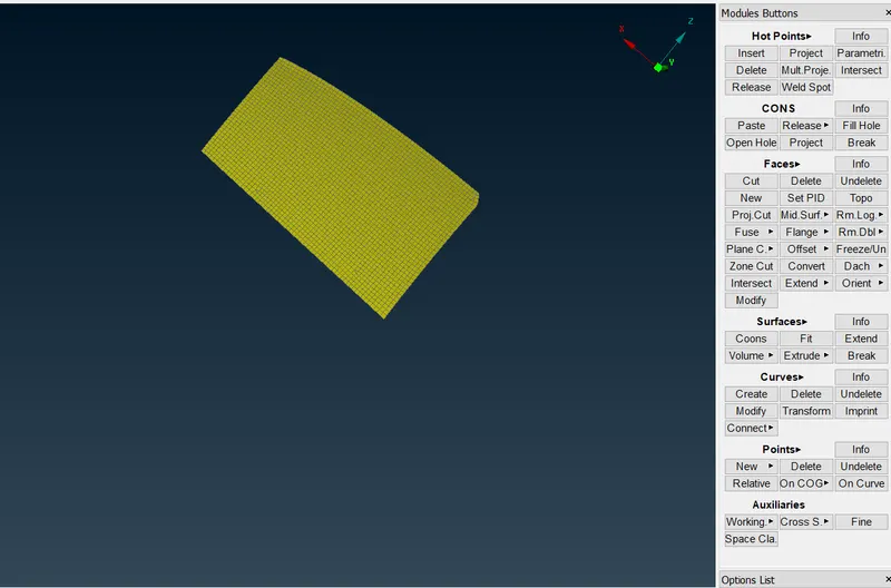
Topo – faces – Set PID – select surface
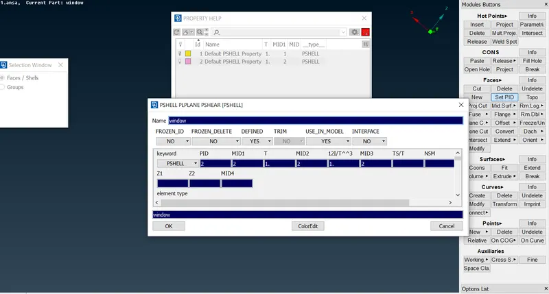
Similarly, assign the property to individual parts
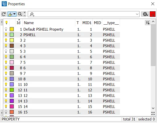
2) Connect the part using different types of connector
Before realizing the connector it is essential to know that, how the parts are connected, what physical change the material is undergoing during the loading, according to this parameter we have to deploy different types of connector. As of now, we are working on the Nastran desk i.e. NVH analysis we have to connect the parts using spot weld or rbe2 elements. As the model is to constrain only.
A) Connection of RBE2 elements :
Nastran Deck – elements – Rbe2 – select nodes – select master node ok

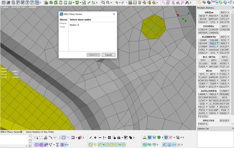
RBE2 elements are rigid elements used to connect two parties with infinite stiffness elements.
B) Connection of Bolt:
We can connect the bolted region with rbe2 elements still, there is an alternative method to connect the bolted region
i) Create a point at the center of using the COG point option.
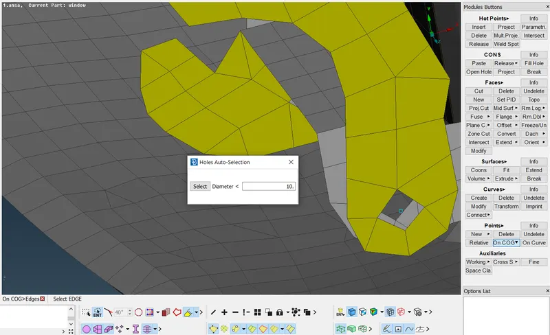
ii) Convert COG point to connector
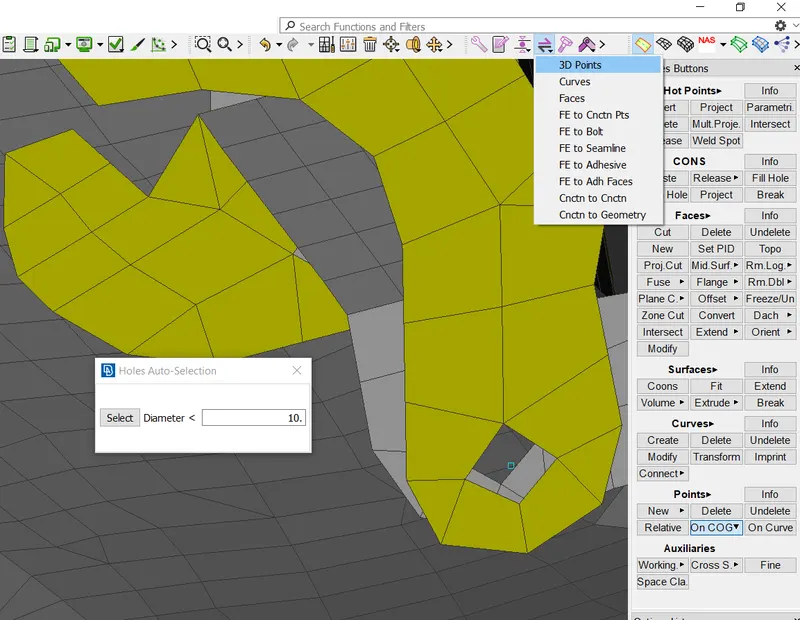
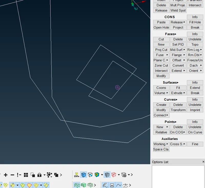
iii) Realize the connector
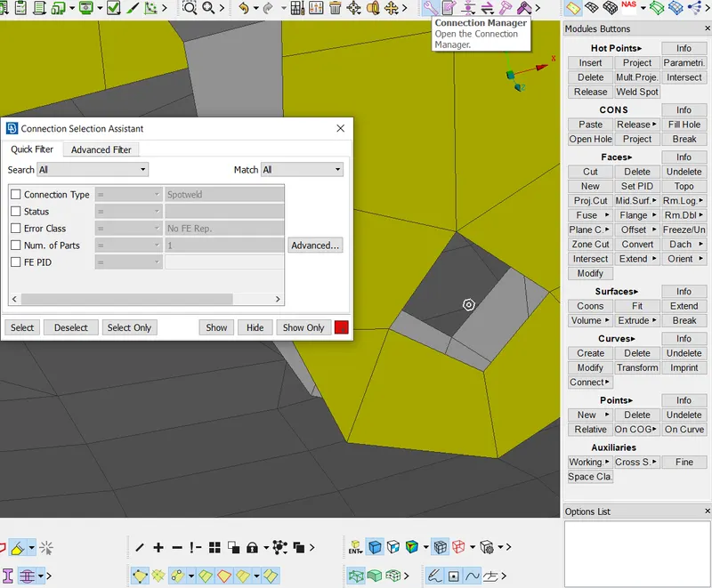
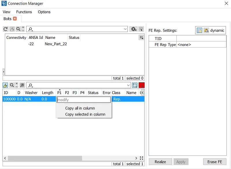
Select P1 and P2 as the surface to be connected
In FE type select bolt and search distance as 20, it is the distance at which software will try to connect surfaces and then realize it.
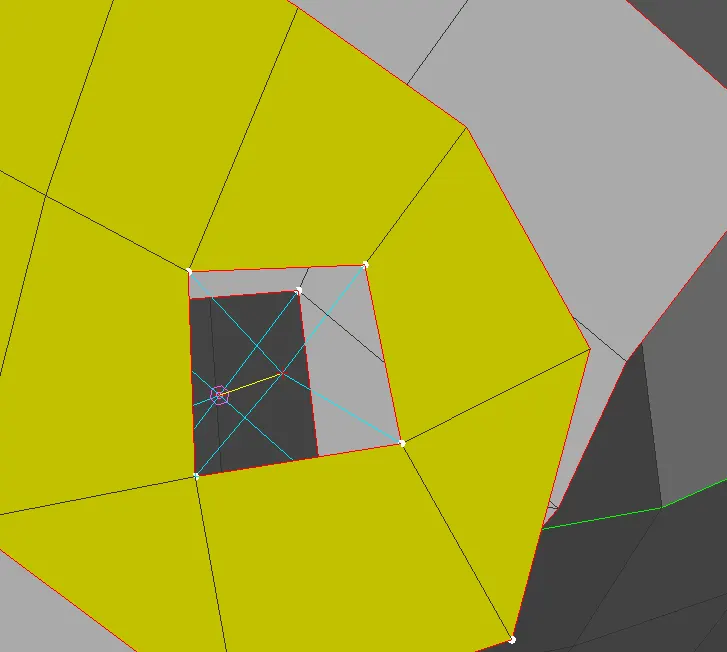
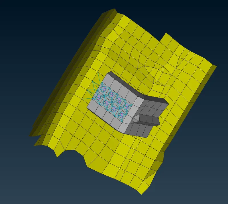
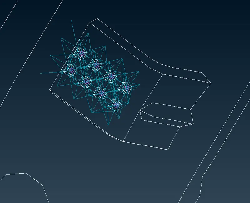
C) Connection of parallel surface using spot weld:
i) Create a COG point at the center of the element
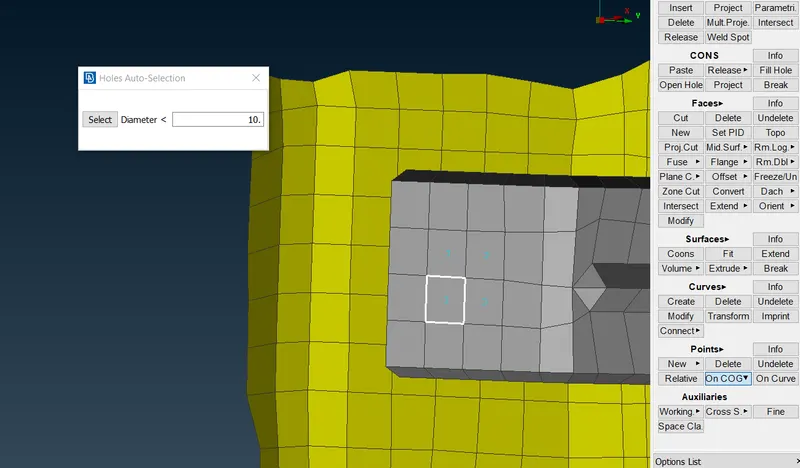
ii) Convert COG point to the connector
While converting the 3D point, save the point as a spot weld.
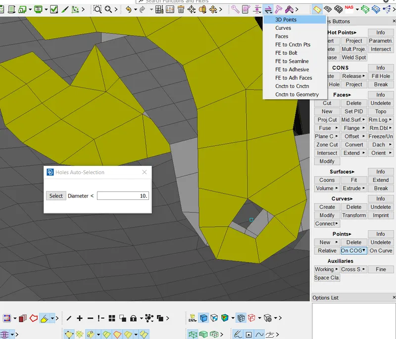
iii) Realize the connector
Select P1 and P2 as the surface to be connected
In FE type select rbe3 Hexa rbe3 element type and search distance as 20, it is the distance at which software will try to connect surfaces and then realize it.
D) Connection using Bush elements
While connecting the window to the surface there should be a spring effect in the elements connecting two surfaces in such condition using of rbe3 bush elements are mostly used.
i) Create the connector curve
In this model, we don’t geometry, in such a case convert the FE model edge to the curve to specify the connector. As the bush elements are to be connected between the window and the side panels it is important to replicate the curve as connectors are to be deployed at two different positions.
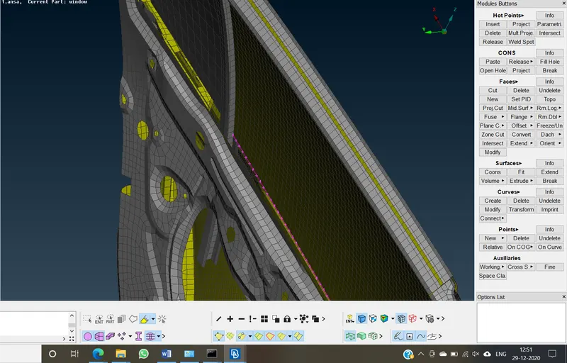
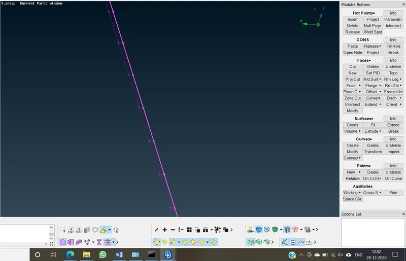
ii) Convert curve to the connector
In this type, we have to create a connector using seam line.
iii) Realizing the connector:
Select P1 and P2 as the surface to be connected
In FE type select rbe3 bush rbe3 element and search distance as 20, it is the distance at which software will try to connect surfaces and then realize it.
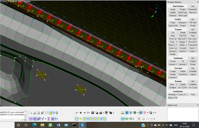
In some regions the connector will realize using a local coordinate system, the difference in the coordinate system will result in deviation of true value, so it is advisable to convert it to the global coordinate system.
Conclusion:
1) Learned how to connect different surfaces using different types of elements and connector types.
2) Got to know different types of connector and their physical properties.
Final model: