Week 6-3D Tetra Meshing Challenge
PROJECT REPORT
AIM:
Create a Teramesh for the Housing component with the given quality criteria Using different TetraMesh Generation methods.
Method 1: 2D to 3D Conversion
Method 2: Quick Tetra Mesh/ Volume Tetra Mesh
OBJECTIVES:
- To check and correct geometrical errors on Geometry.
- Generating 2D Tria mesh on the given component with proper mesh Flow.
- Covert the 2D tria mesh into 3D Tetramesh.
- Generating 3D Tetramesh directly by Volume Tetra Mesh.
BODY OF THE CONTENT:
This is the model 1,
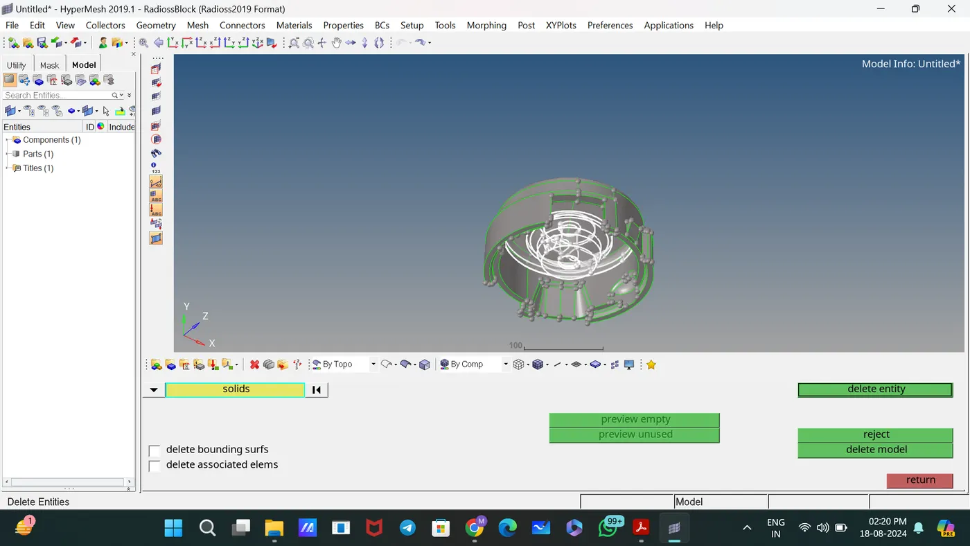
Deleted unwanted solids [Delete—select the solids].
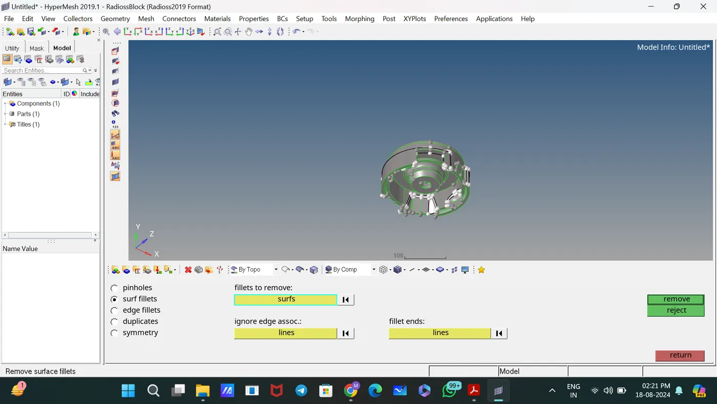
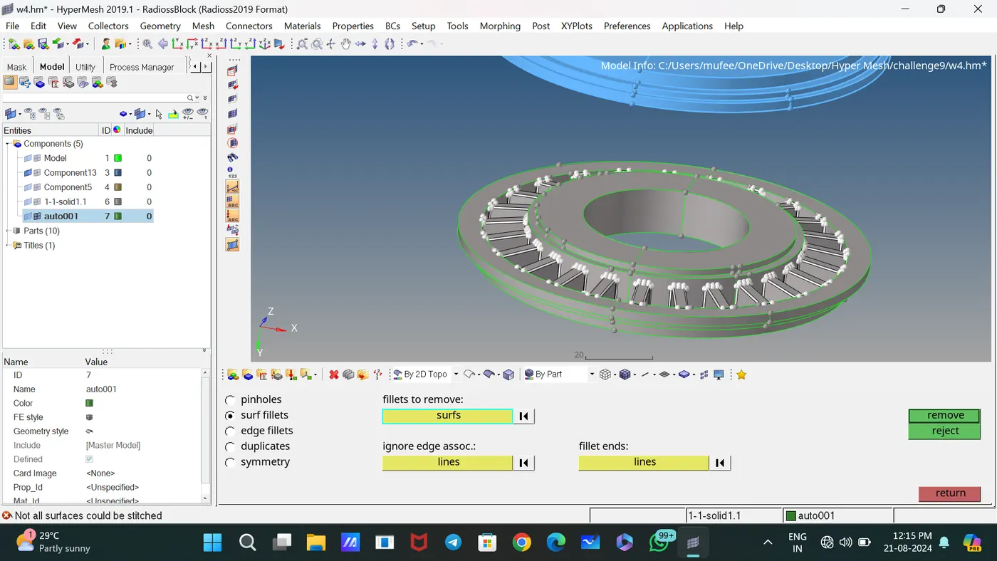
Used the Edge Fillets subpanel to identify and remove edge fillets with specified dimension.
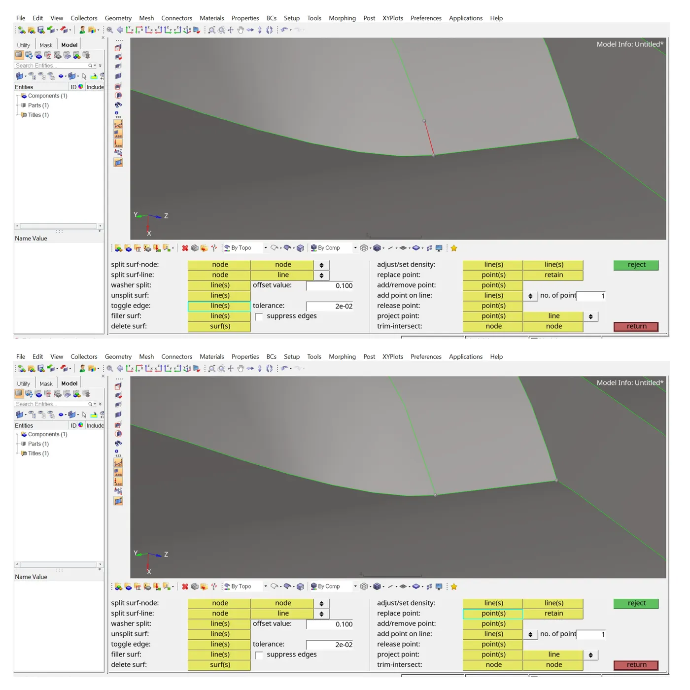
Used the Toggle subpanel to toggle edges for proper connection between Surfaces.
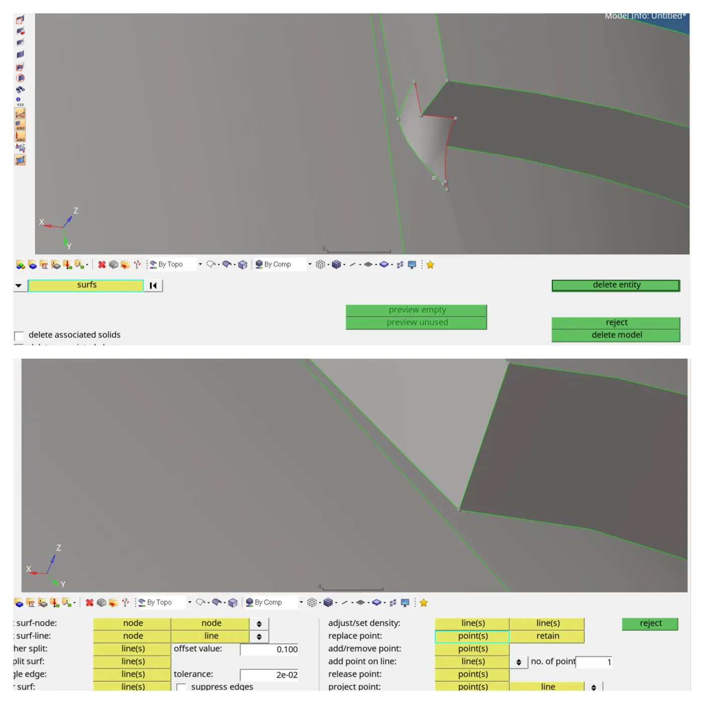
Deleted the damaged surface and created new surfaces by spline surf.
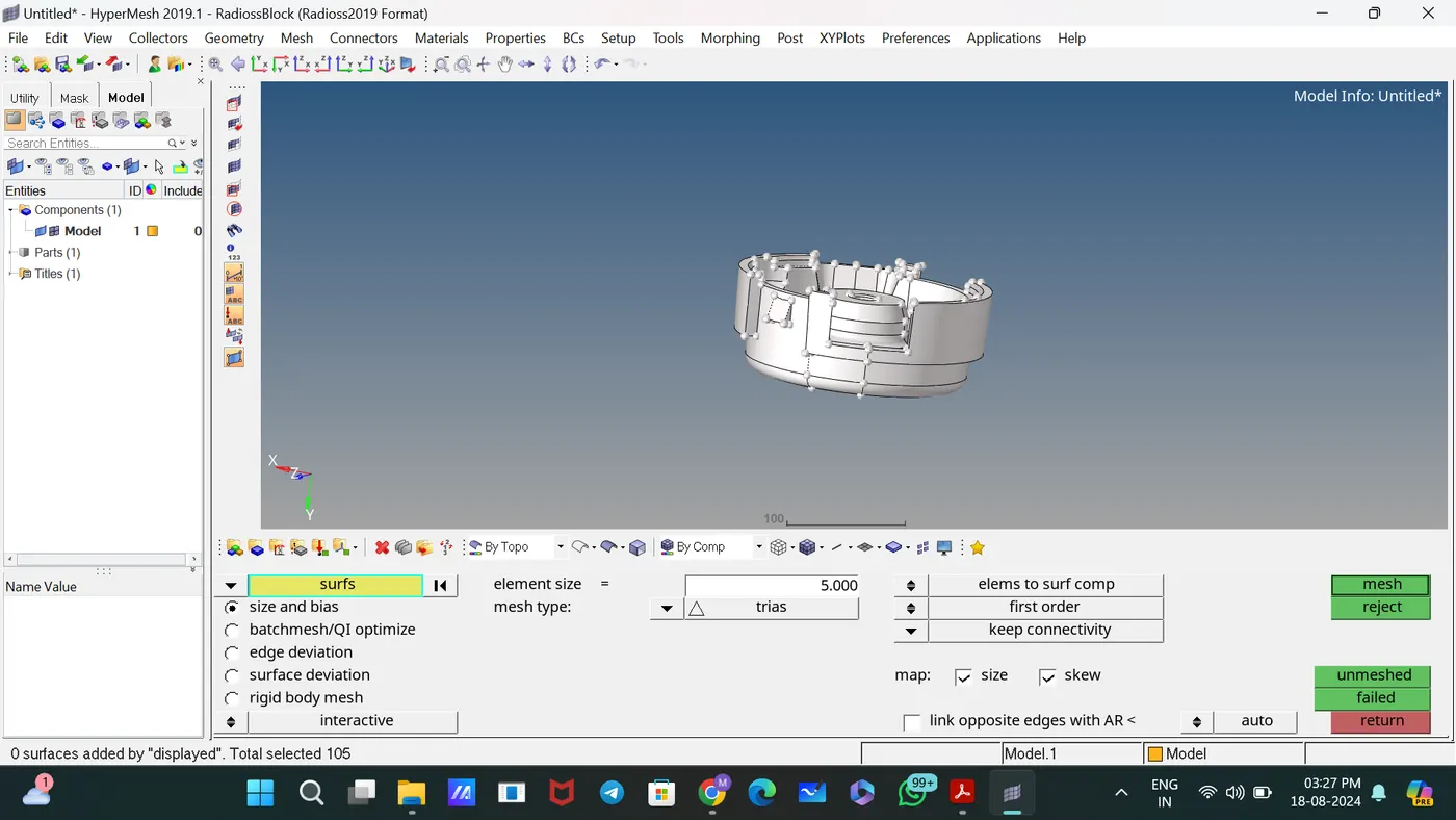
Generated 2D Tria mesh on the given component with proper mesh Flow by giving element length value and mode of mesh.
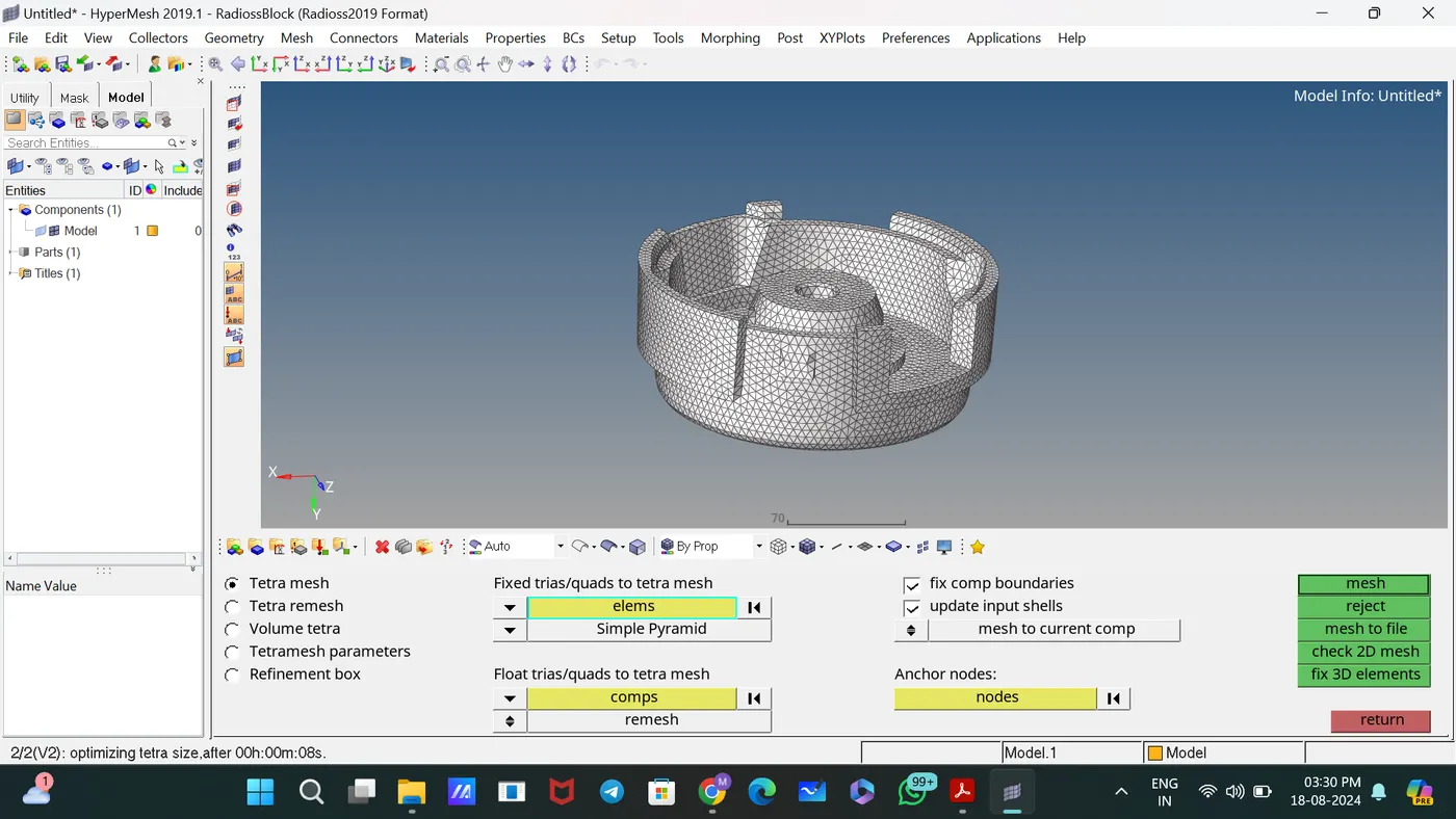
Generated 3D Tetramesh by selecting 2D elements [3D—Tetramesh].
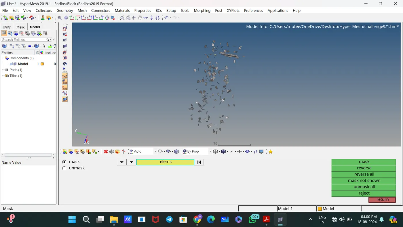
Masked the failed tetra elements [Tet collapse] to make the work easier.
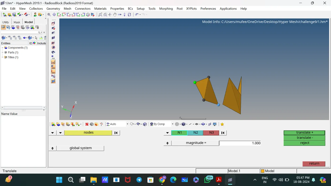
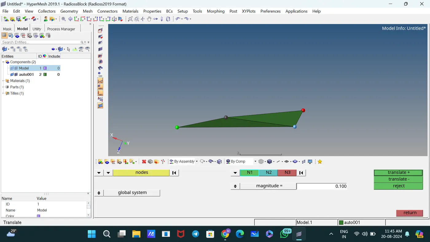
Used Translate subpanel to correct tet collapse failure.
In this situation, use the Replace command to join the elements.
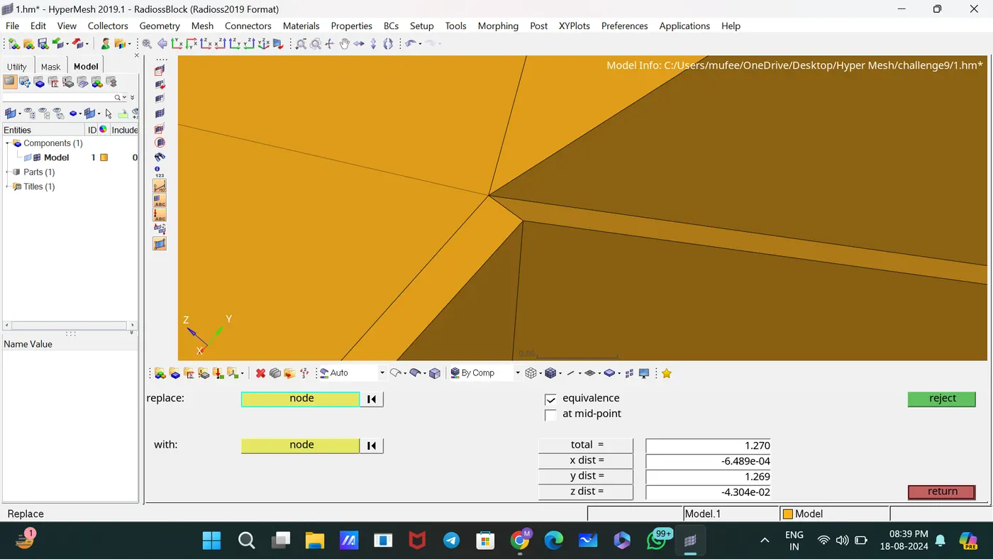
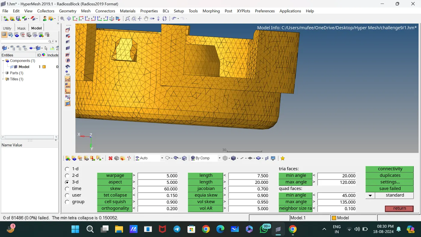
Corrected all failed elements. Now the component is 0 Tet collapse Failure.
Checked Tet collapse using the subpanel Check Elements.
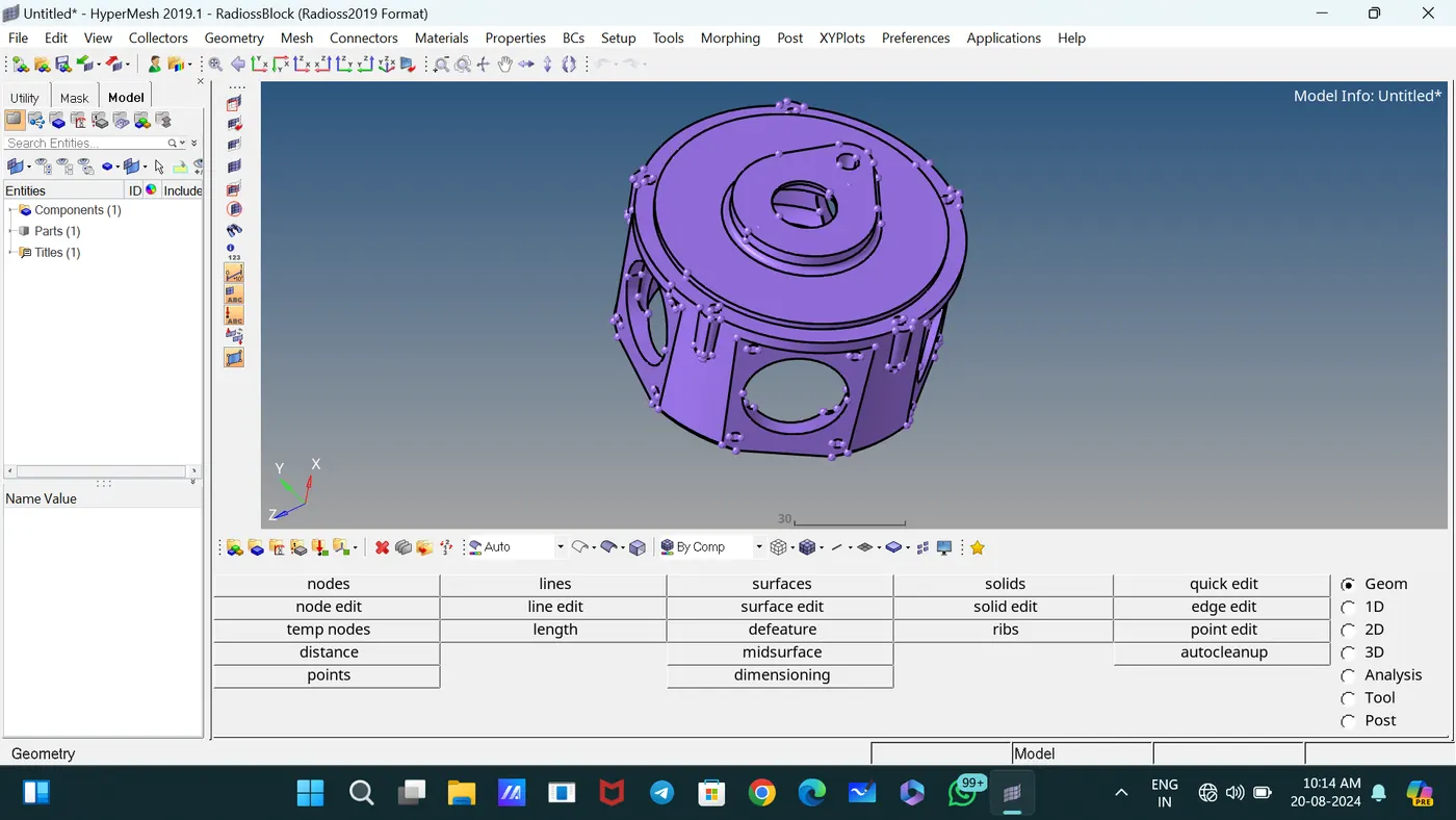
MODEL 2,
This is CAD Geometry of Component.
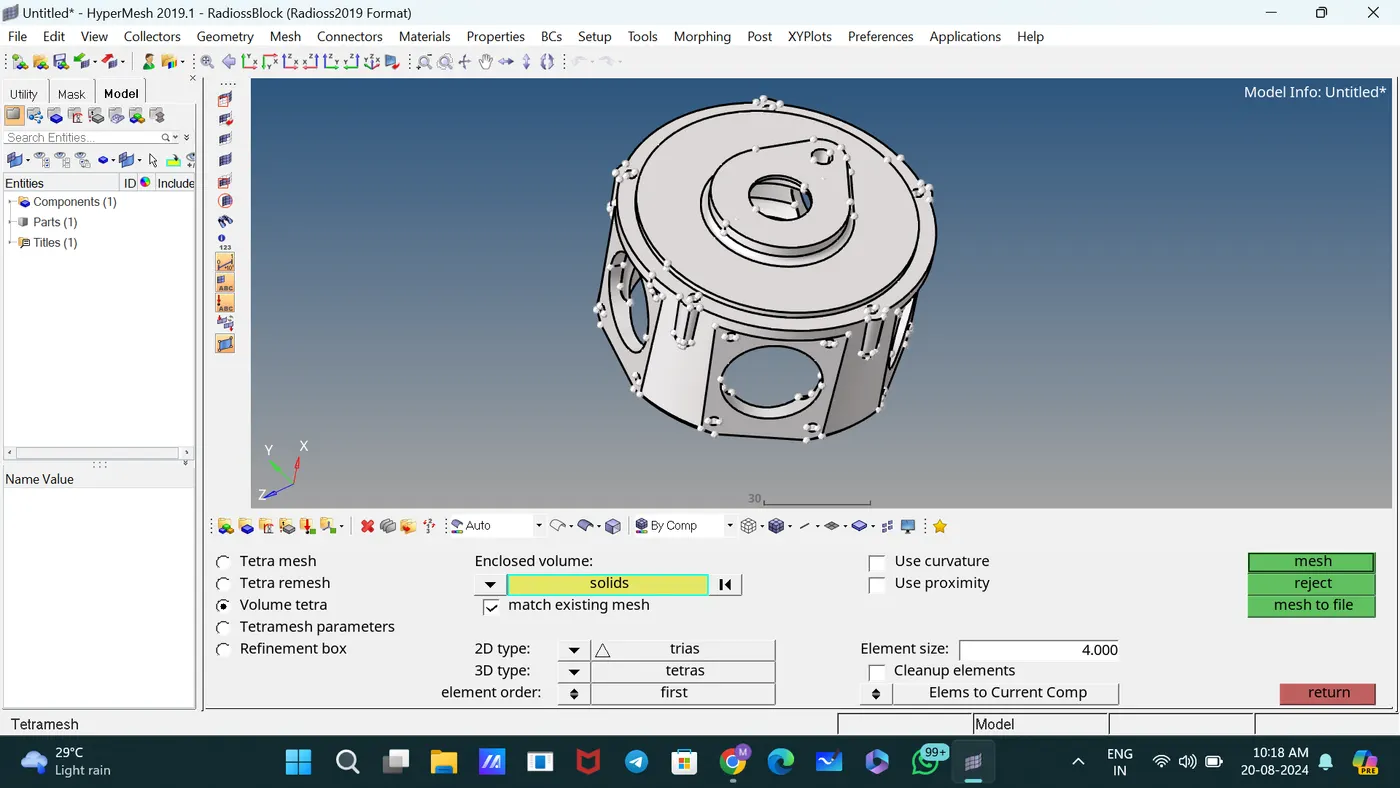
Generated 3D Tetramesh directly by Volume Tetra Mesh. [3D—Tetramesh--Volume Tetramesh].
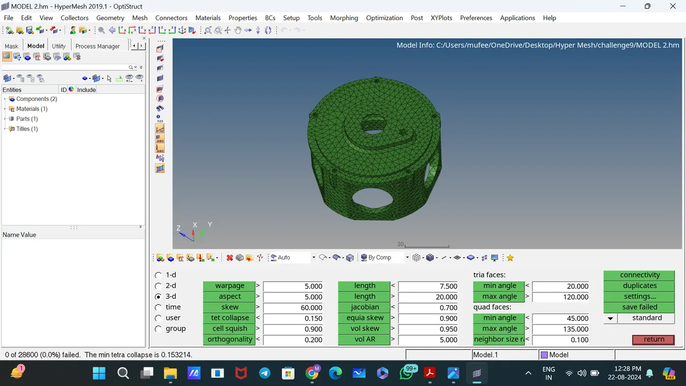
Used Translate subpanel to correct tet collapse failure.
Checked Tet collapse using the subpanel Check Elements.
MODEL 3,
Isolated each component to make the work easier.
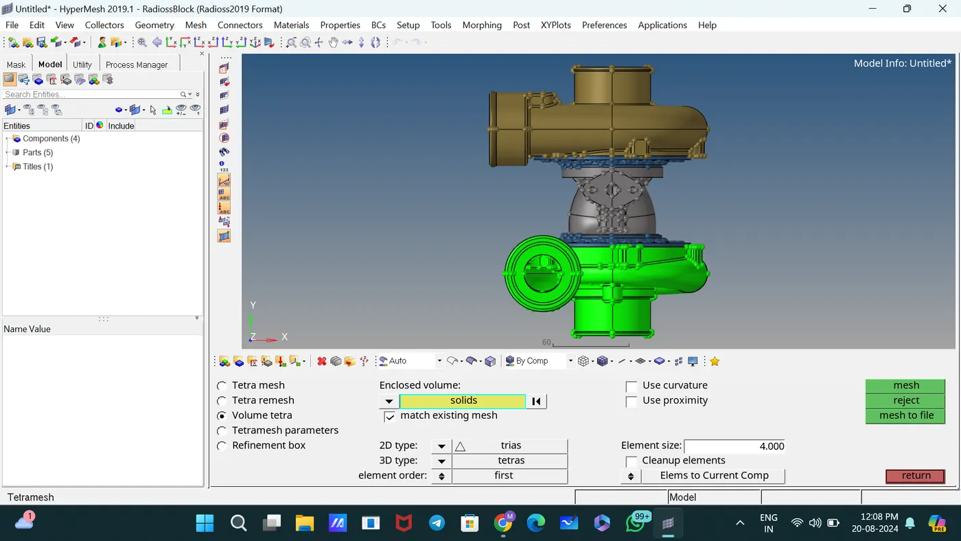
It showed an error when doing Voule Teramesh and Quick Tetramesh.
Hence Trimmed the symmetric Solid into 2 and proceeded with solid mesh.
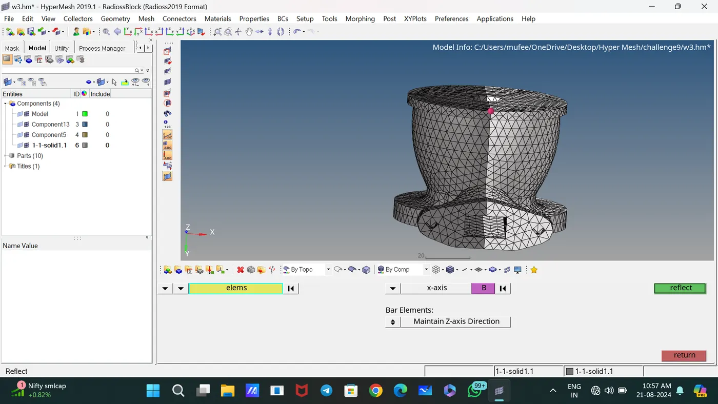
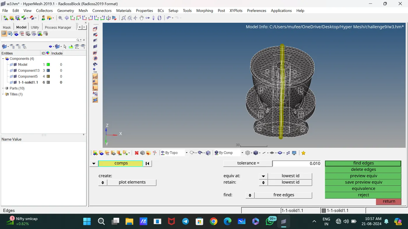
Reflected the symmetric part and joined using equivalence.
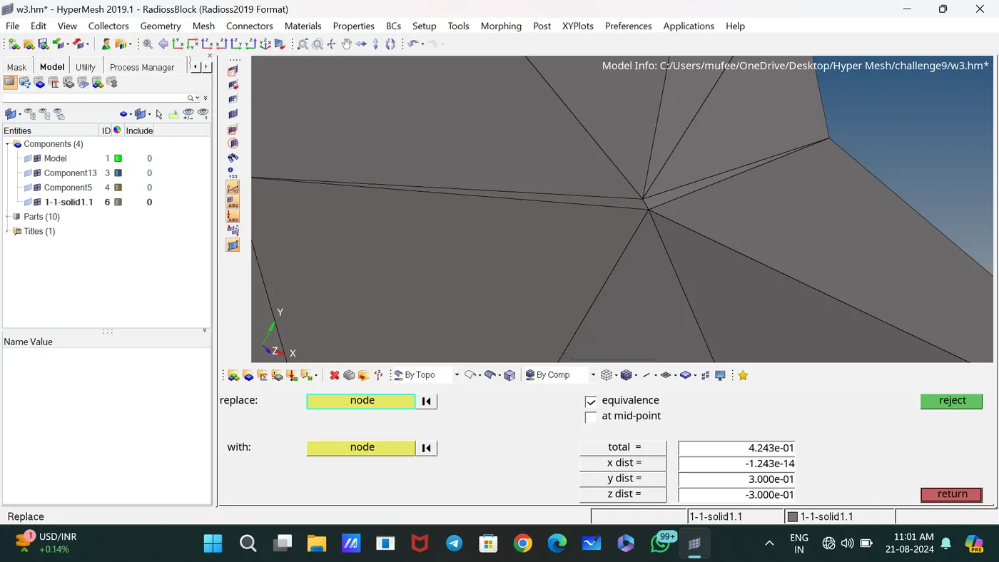
In this situation, use the Replace command to join the elements.
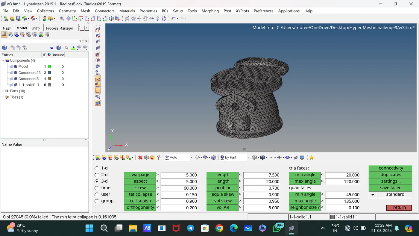
Checked Tet collapse using the subpanel Check Elements.
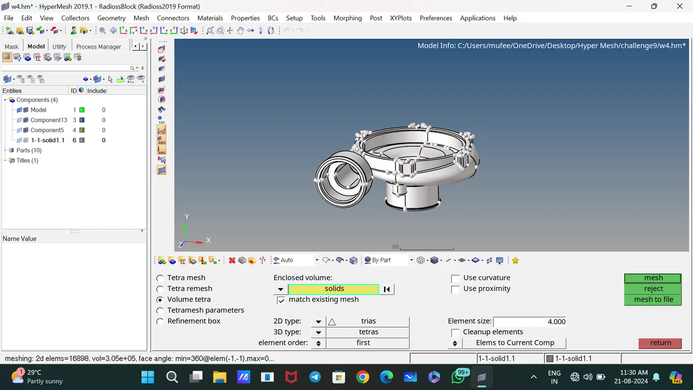
Generated 3D Tetramesh directly by Volume Tetra Mesh.
Used Translate subpanel to correct tet collapse failure and Checked Tet collapse using the subpanel Check Elements.
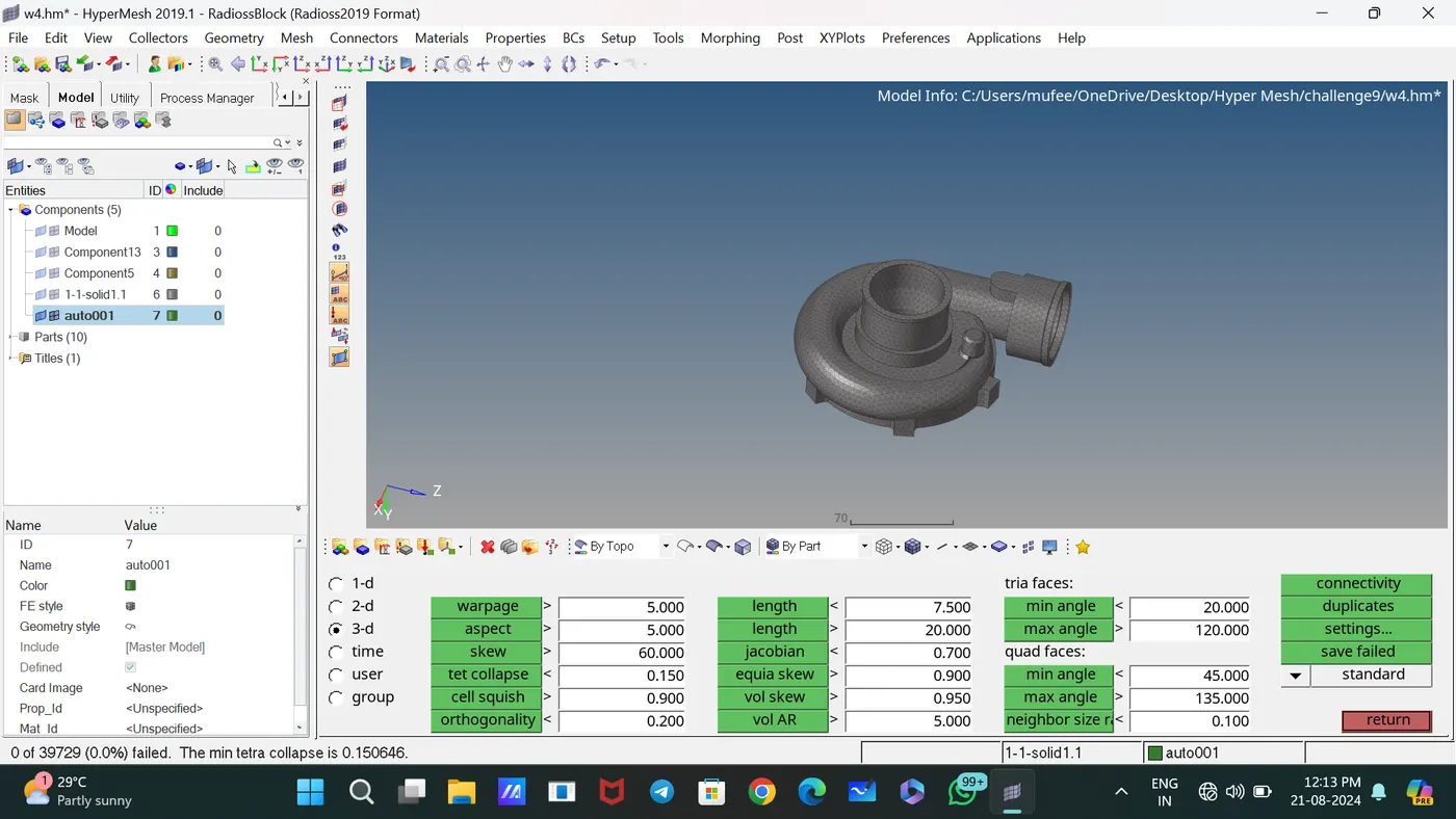
Used the Edge Fillets subpanel to identify and remove edge fillets with specified dimension.
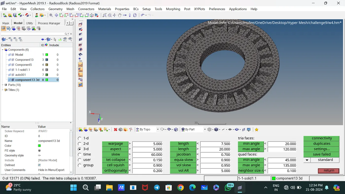
Generated 3D Tetramesh directly by Volume Tetra Mesh.
Used Translate subpanel to correct tet collapse failure and Checked Tet collapse using the subpanel Check Elements.
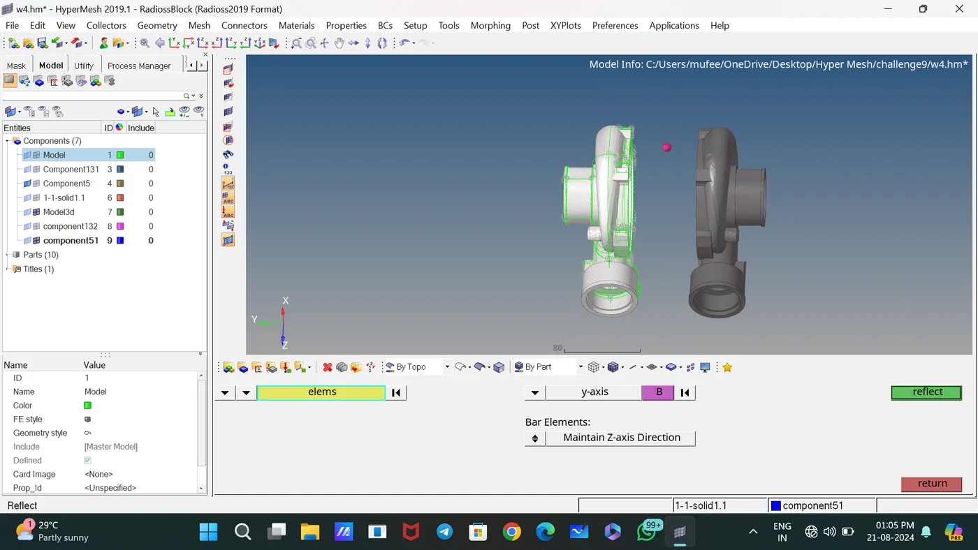
Used the Reflect command to reflect the symmetric elements [tool—Reflect]
Used the Rotate command to Rotate the elements about an axis concerning the base point.
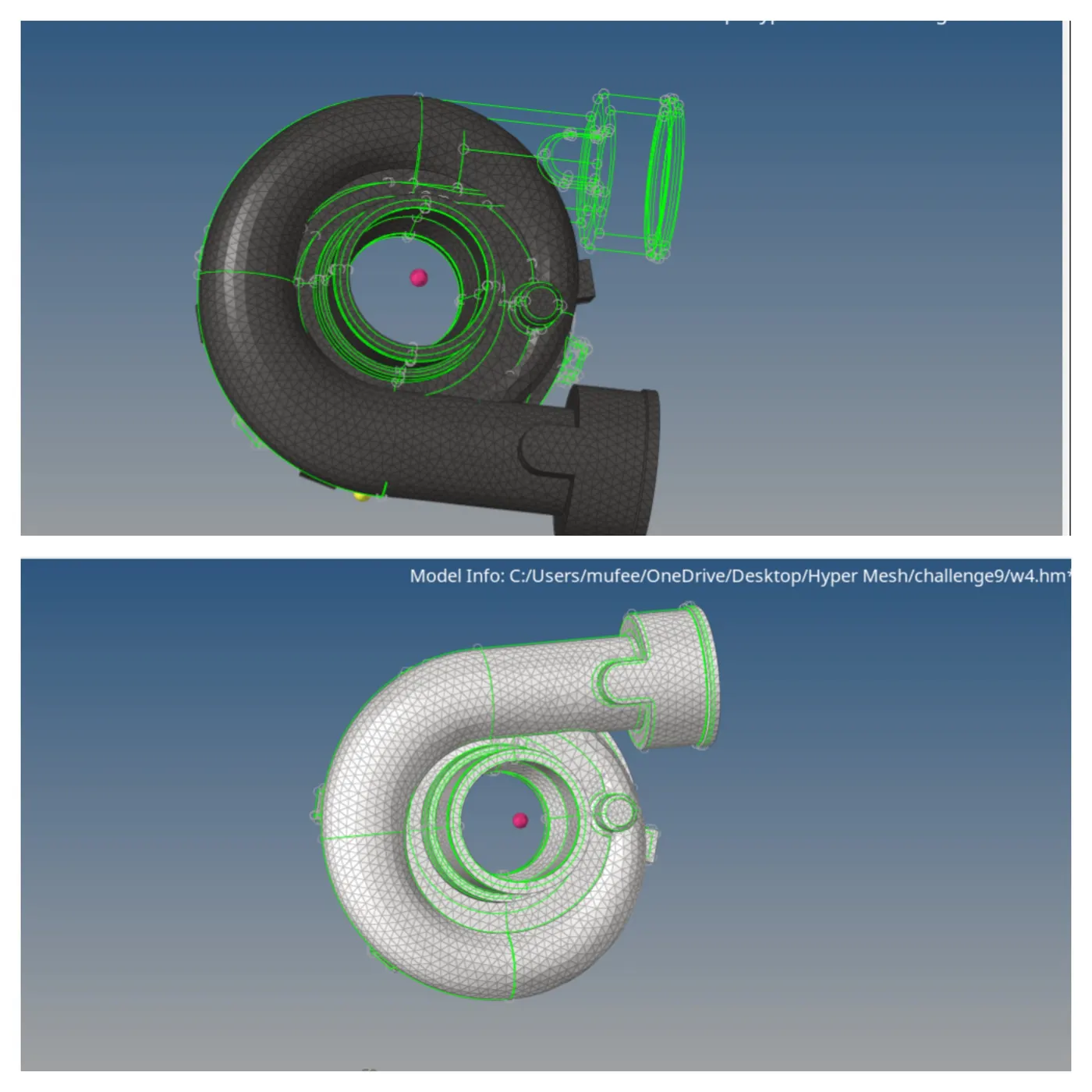
Compteled the 3D meshing and Removed all 2D element shells by deleting by configuration command.
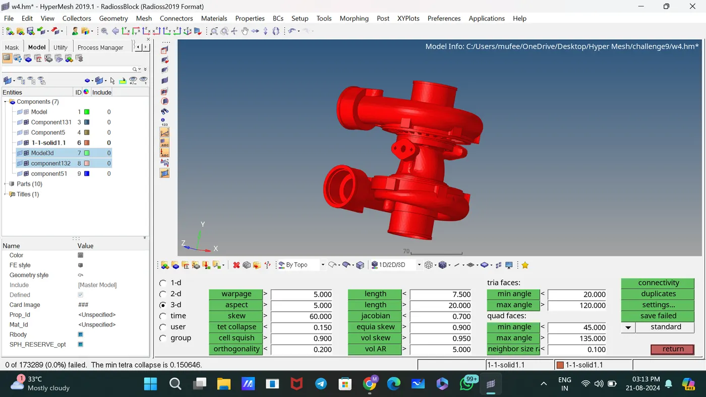
CONCLUSION:
Evaluating the creation of a Teramesh for the housing component with specific quality criteria using different tetrahedral mesh generation methods, we have observed distinct outcomes based on the methods employed.
Method 1: 2D to 3D Conversion
The 2D to 3D conversion method effectively generated a tetrahedral mesh by extending 2D geometrical information into the third dimension.
Method 2: Quick Tetra Mesh/Volume Tetra Mesh
The Quick Tetra Mesh and Volume Tetra Mesh methods delivered refined results, particularly for complex geometries.
Experienced some errors while running in volume Tetramesh.