Week 6-3D Tetra Meshing Challenge
AIM: The main aim of this challenge are as follows:
1) To create 2D tria mesh and convert it into 3D tetra mesh for model-1.
2) To create a quick tetra mesh for models 2&3.
OBJECTIVE: The objectives of this challenge are as follows:
1. Model-1: 2D elements must be created with target element size of 5 units (min &max element size = 2&7 units respectively), and convert these 2D elements to 3D elements using tetra mesh subpanel option without any tet collapse (0.15) failure.
2. To create a 3D quick tetra mesh for models 2&3 without any tet collapse (0.15) failure.
PROCEDURE:
Model-1:
1) In this challenge, there are totally 2 components and each of them should be meshed separately.
2 The CAD file was imported using import geometry option.
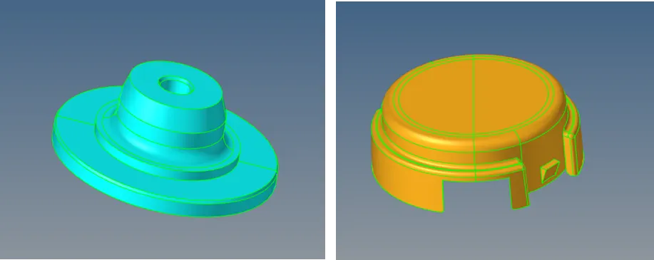
3) After importing the geometry, any free edges or non-manifold edges needs to be removed before performing meshing.
4) Defeaturing is done where ever it is required so that the 2D elements are free from min and max length elemental failures.
5) After defeaturing, tria mesh (2DàAUTOMESHàMESHTYPEàTRIASàELEM SIZE=5) was deployed on the components with element size of 5 units.
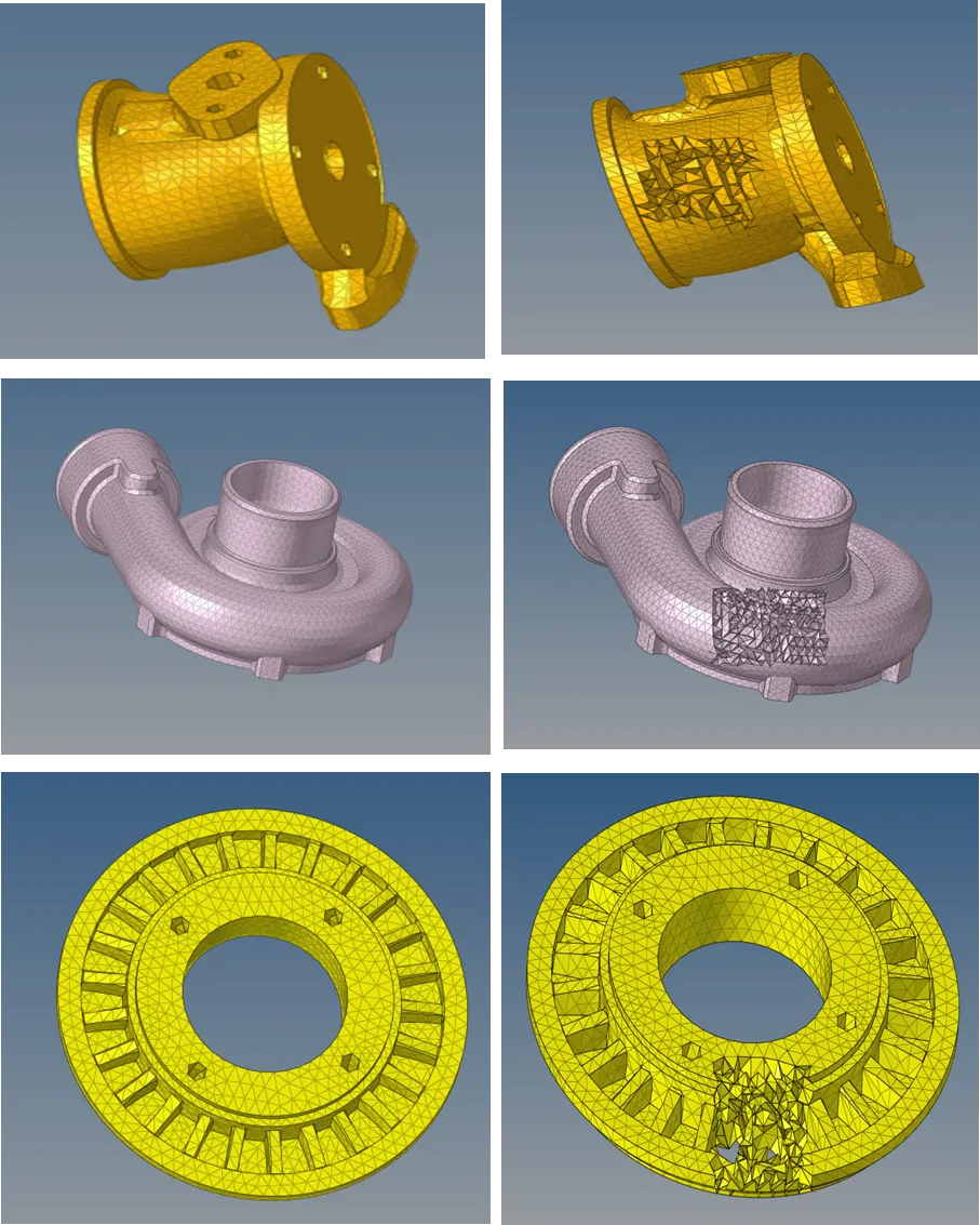
6) 2D elements were converted into tetra mesh by using tetra mesh subpanel(3DàTETRAMESH) option and final 3D mesh images are shown below. By masking (TOOLSàMASKàELEMENTS) some of the elements we can confirm the formation of tetramesh.
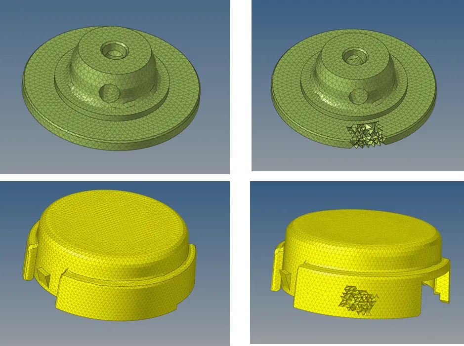
7) After deploying 3D mesh tet collapse must be checked using check elements subpanel option (TOOLSàCHECK ELEMENTSà3DàTET COLLAPSE=0.15). Tet collapse failure elements can be corrected either by tetra remesh (3DàTETRAREMESH) or translate (TOOLSàTRANSLATE) option.
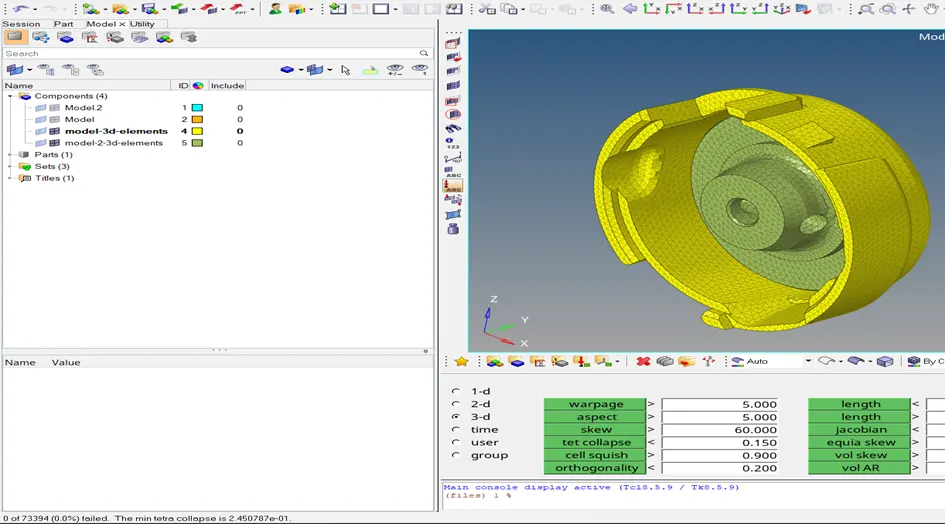
8) Finally after creation of 3D elements, 2D elements were deleted.
Model-2:
1) In this challenge, quick tetramesh must be deployed on the component without any tet collapse elemental failure.
T The given FE model file was imported by using import geometry option.
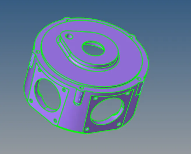
3) Quick tetra mesh (VIEW à BROWSERSà HYPERMESHà UTILITYà GEOM/MESH à QUICK TETRA MESH) was deployed on the component by giving target element size =3 units, min element size=0.8 units and mesh type as trias only.
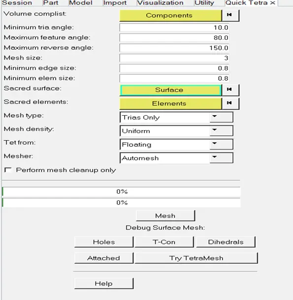
4) After the inputs are given, it automatically toggles unwanted edges and creates 2D elements first and then it will convert those 2D elements into 3D elements.
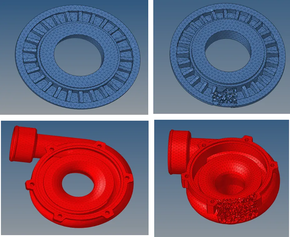
5) The final images of 3D tetra mesh of the component are shown below.
6) By masking (TOOLSàMASKàELEMENTS) some of the elements we can confirm the formation of tetramesh.
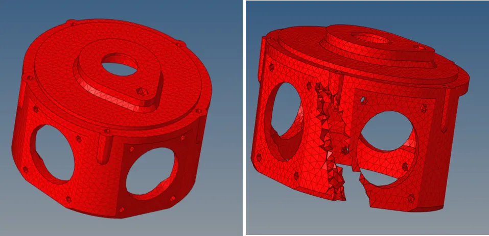
7) After deploying tetramesh, tet collapse must be checked using check elements subpanel option (TOOLSàCHECK ELEMENTSà3DàTET COLLAPSE=0.15). Tet collapse failure elements can be corrected either by tetra remesh (3DàTETRAREMESH) or translate (TOOLSàTRANSLATE) option.
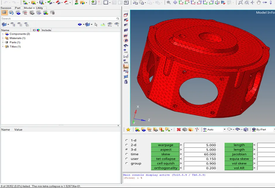
8) Finally after creation of 3D elements, 2D elements were deleted.
Model-3:
1) In this challenge, there are totally 5 components and each of them should be meshed separately using quick tetra option.
2) The CAD file was imported using import geometry option.
3) 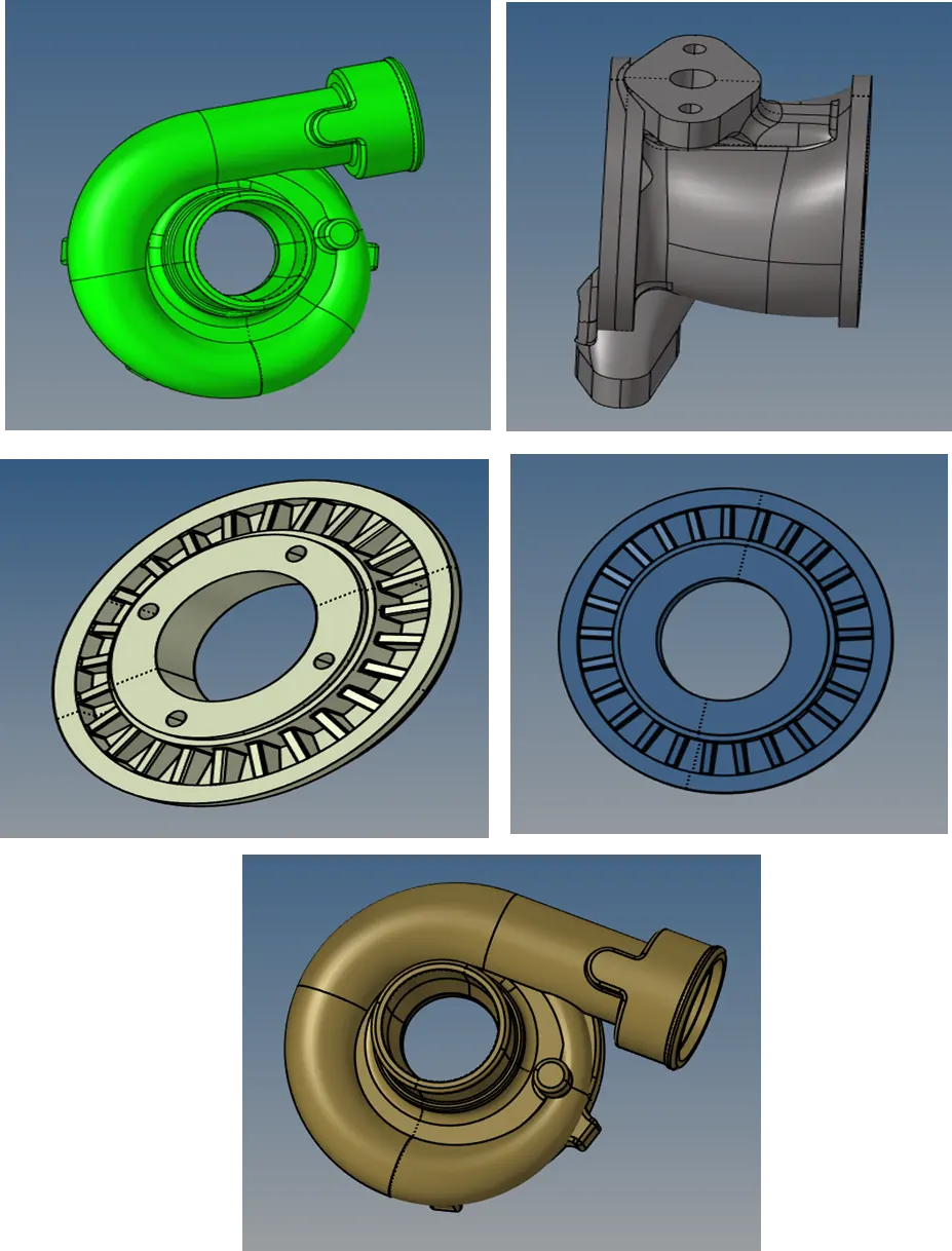
The same procedure as of Model 2 i.e from step-3 to step-8 were followed for this model to deploy quick tetra mesh and the final tetra mesh images of the components are shown below.
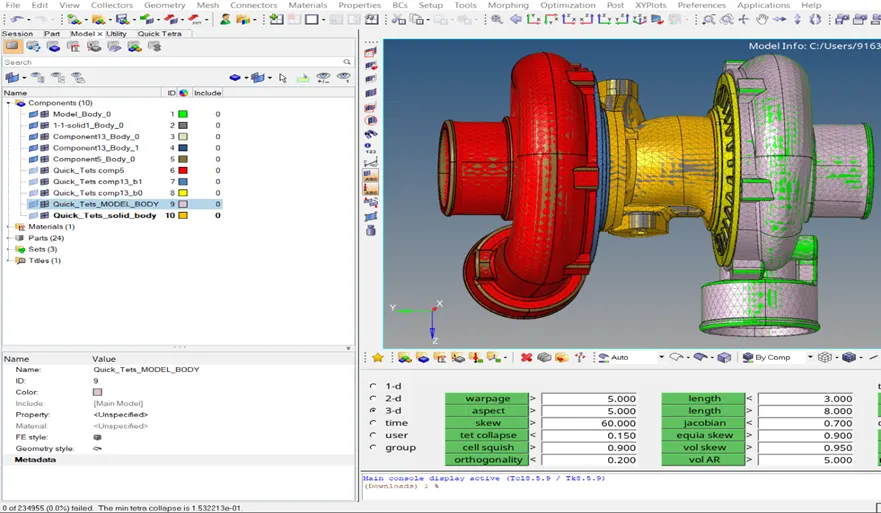
4) After deploying tetra mesh, tet collapse must be checked using check elements subpanel option (TOOLSàCHECK ELEMENTSà3DàTET COLLAPSE=0.15). Tet collapse failure elements can be corrected either by tetra remesh (3DàTETRAREMESH) or translate (TOOLSàTRANSLATE) option.
RESULTS:
1) Successfully deployed tetra mesh on the given models according to the given techniques in the question without any elemental failure.