Week 6
* Objective:
To implement connections wherever required on the rear door FE model with different types of connection techniques along with different 1D elements using NASTRAN deck.
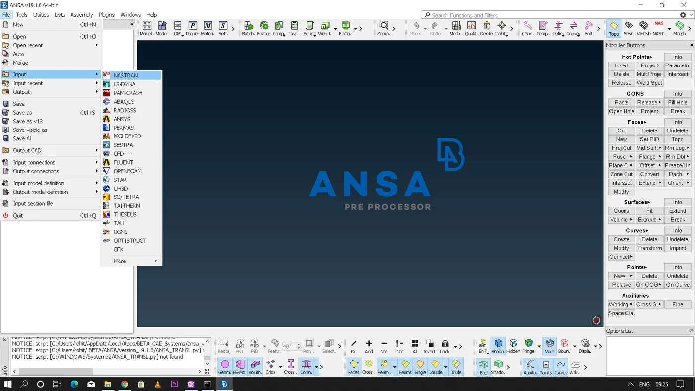
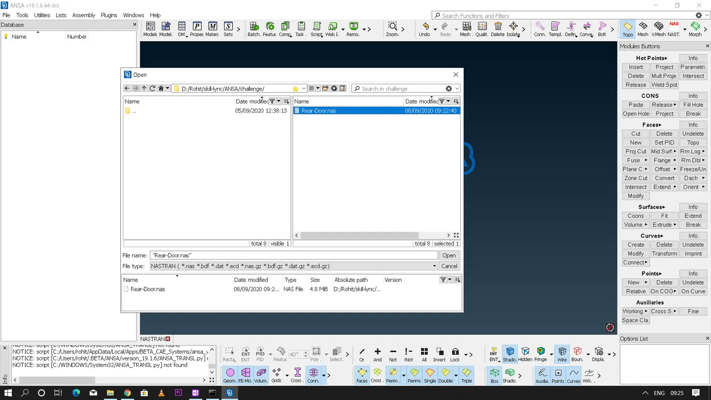
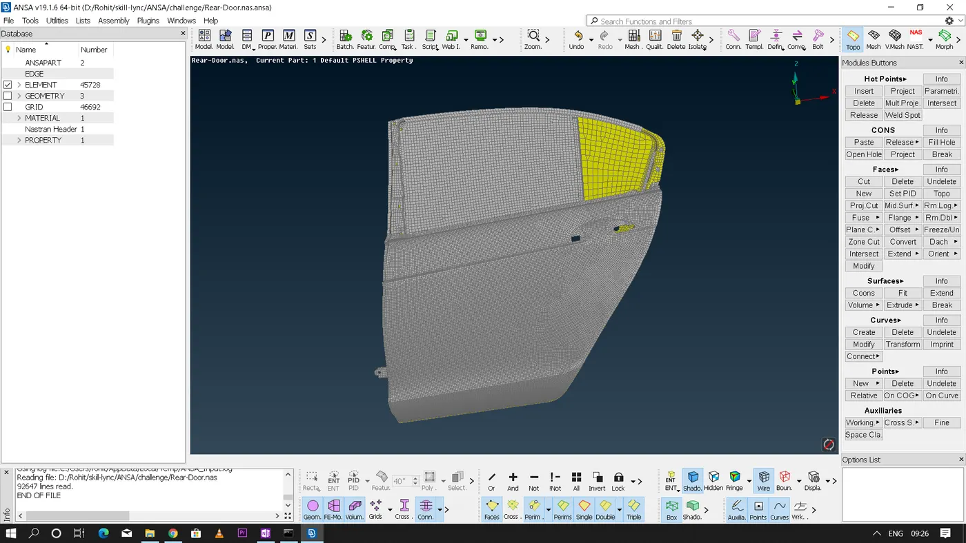
* Steps to be followed for making the rigid connections:
• NASTRAN is an NVH(Noise, Vibration, Harshness) simulation deck.
• In NASTRAN it is better that first we rigidise the component by connecting all the bolts and welds present in the design.
* Now for realizing the bolt connection we have several methods that can be followed in ANSA.
1. By using 'RBE2'(Rigid Body Element 2)
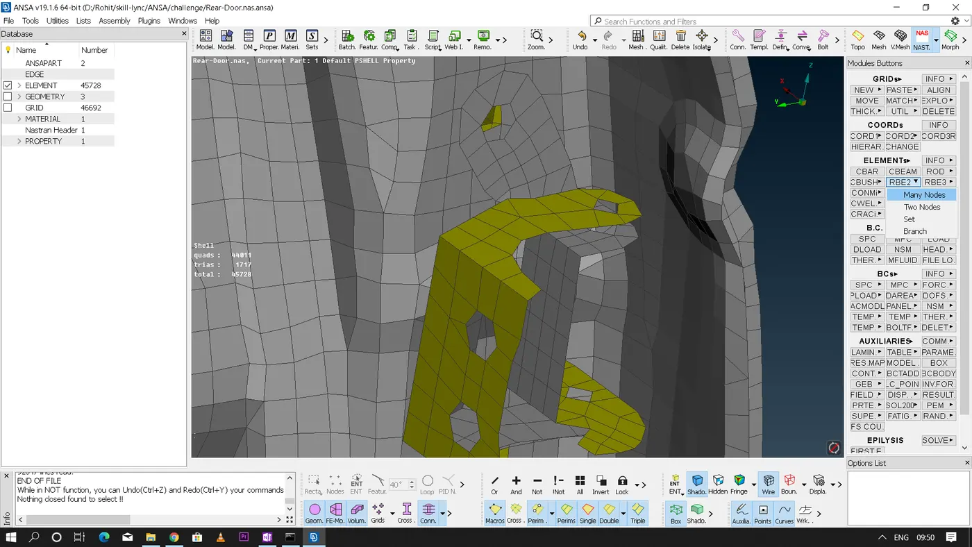
• In NASTRAN deck - elements module - RBE2
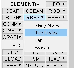
Under RBE2 again we have 4 different options
(a) Many nodes
(b) Two nodes
(c) Set
(d) Branch
• In most of the cases we only use 'Many nodes' and 'Two nodes' options only. As the name itself tells 'Many nodes' option is used to deploy connections for more than two node elements and 'Two nodes' option is used for deploying connection between any two nodes.
• Steps to be followed to deploy a bolt connection
RBE2 - Many nodes - Select the slave nodes - Now ANSA will identify the "COG" and will deploy a master node - Change the part option from 'Ask if needed' to 'Ask always' and click next - Now create a new PartID and assign a new group for all the connections.
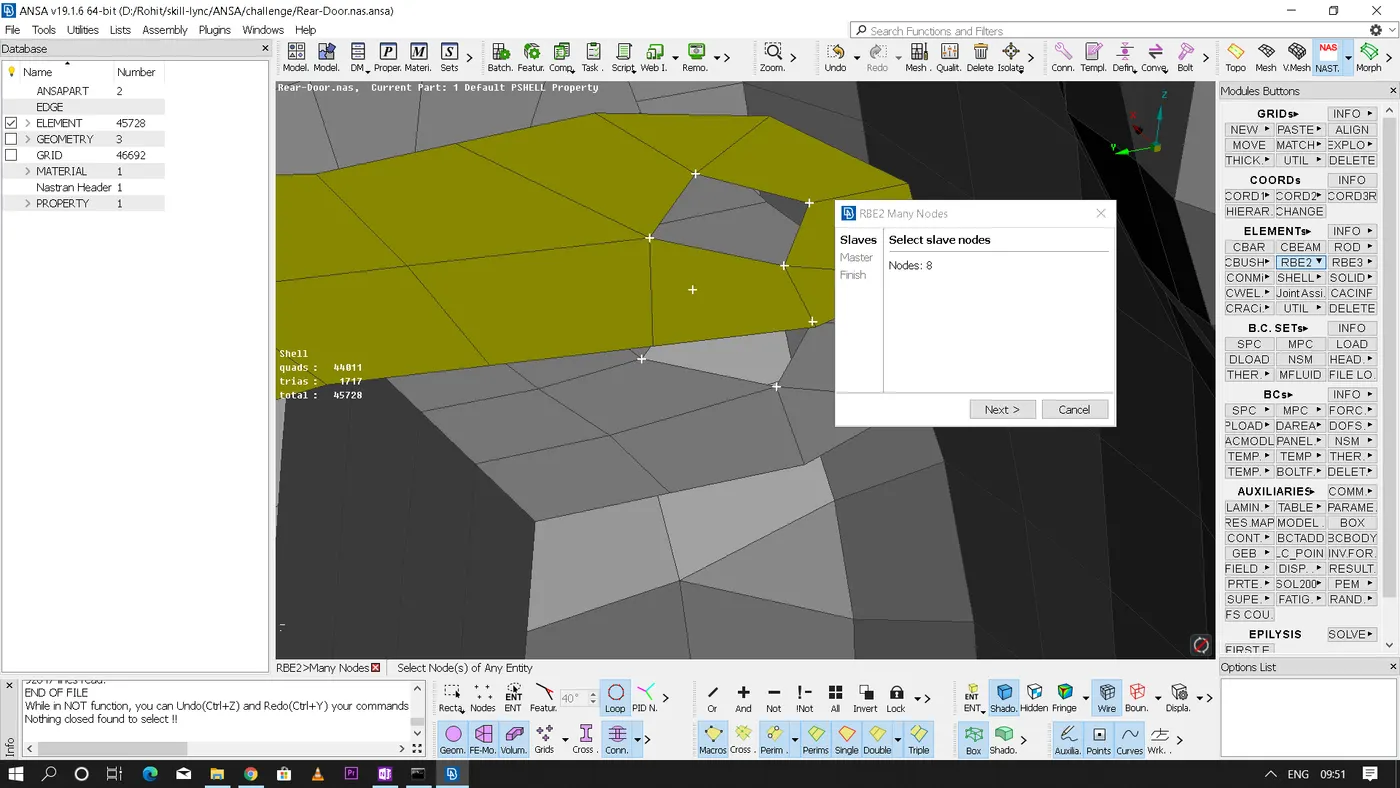
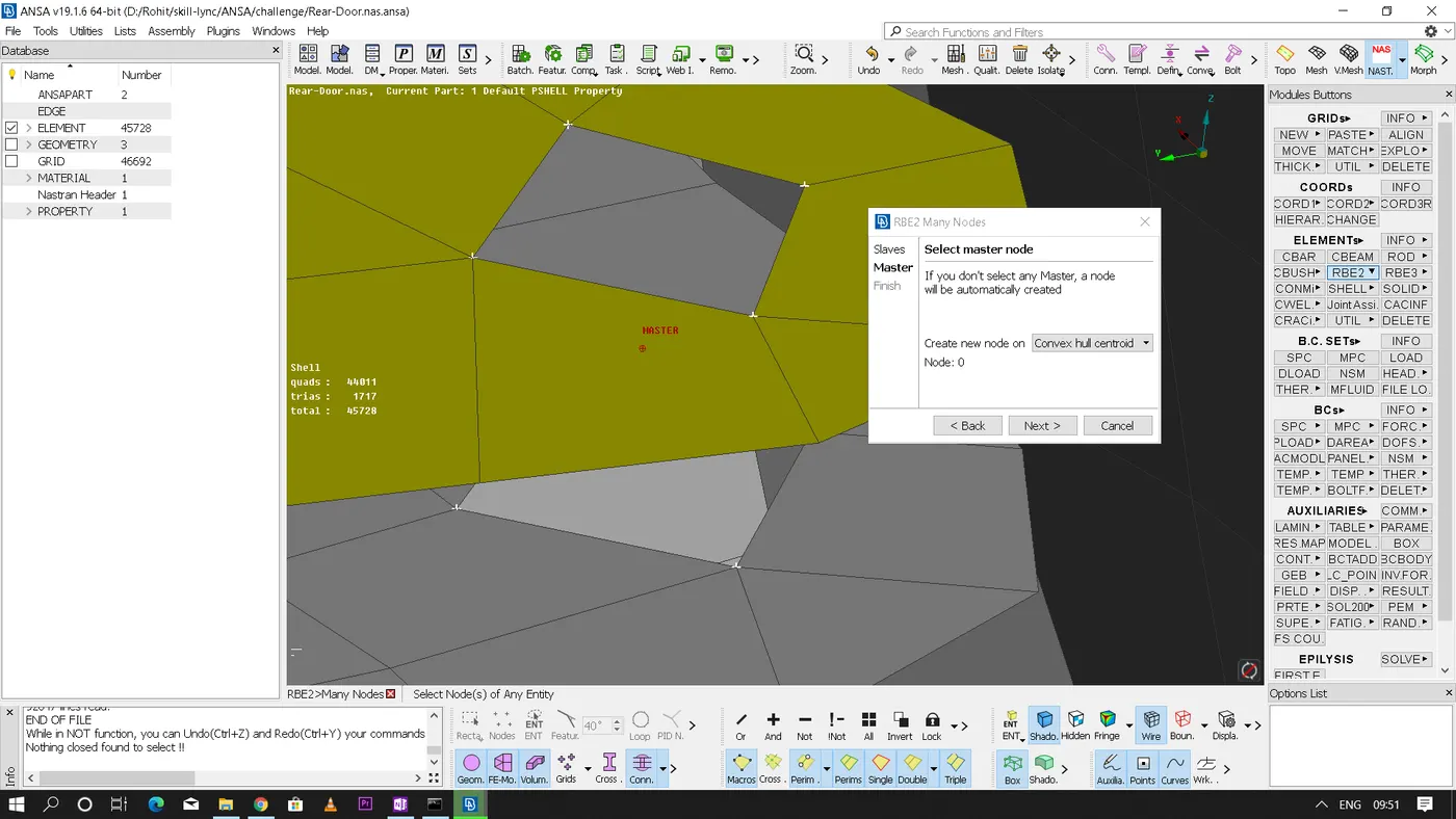
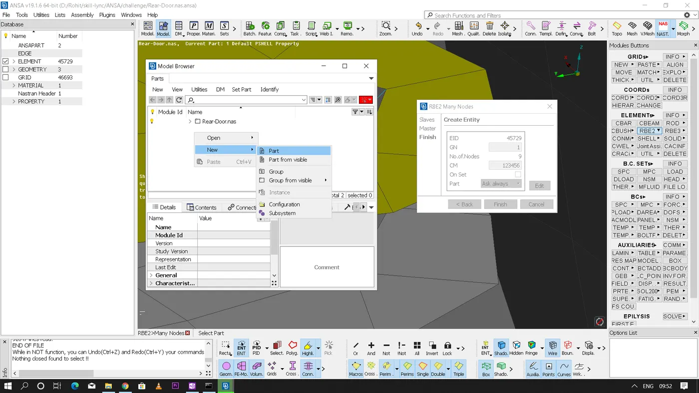
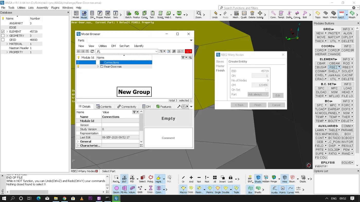
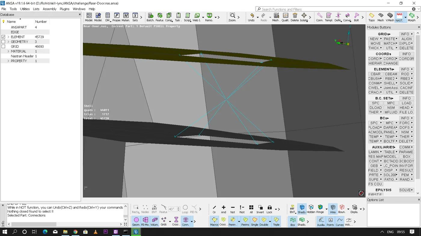
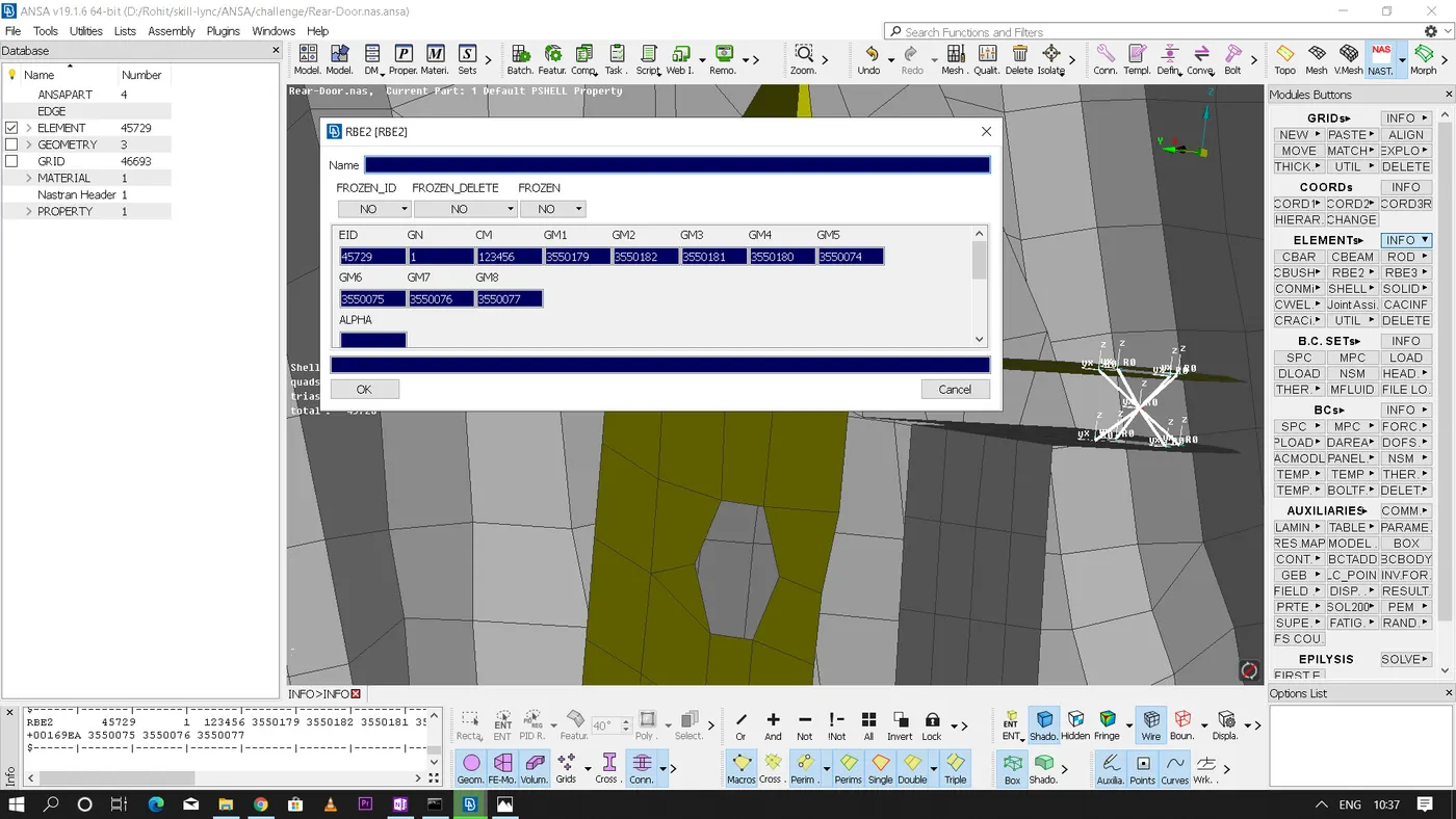
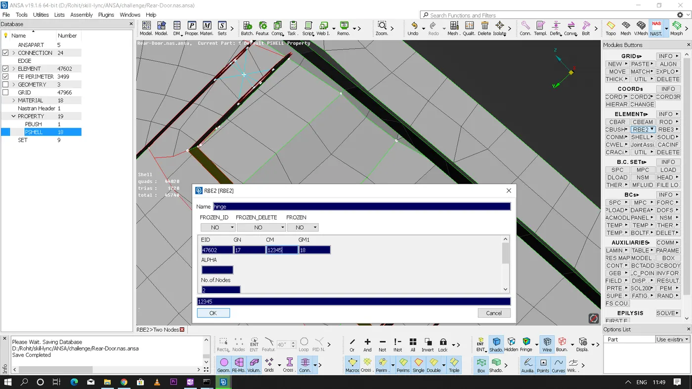
• Now we get an unique element id(EID), master node id/grid id(GN), slave node id's(GM1,GM2,...) and degree of freedom(CM).
• As we know there are 6 DOF i.e, 3 linear and 3 rotational along "X,Y and Z" axis respectively which is denoted from numbers (123456). We can remove any number from the 'CM' option to make the particular part to move in that respective direction as per the mechanism of the part while simulation.
2. Bolt connection with the help of connectors instead of using manual rigid connection
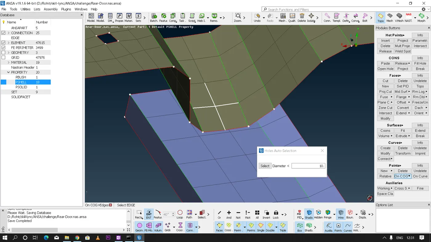
• For this method first we need to create a 3D point for the respective hole where the bold connection has to be realized.
• Steps to be followed:
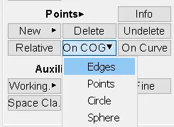
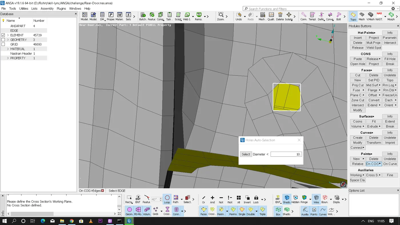
In Topo - points module - on COG - edges - now with the help of loop selection select the hole perimeter - on confirmation we get a 3D point at the COG of the hole
• Now with the help of convert and connect option in the assembly section we need to convert this 3D point into a bolt connection.
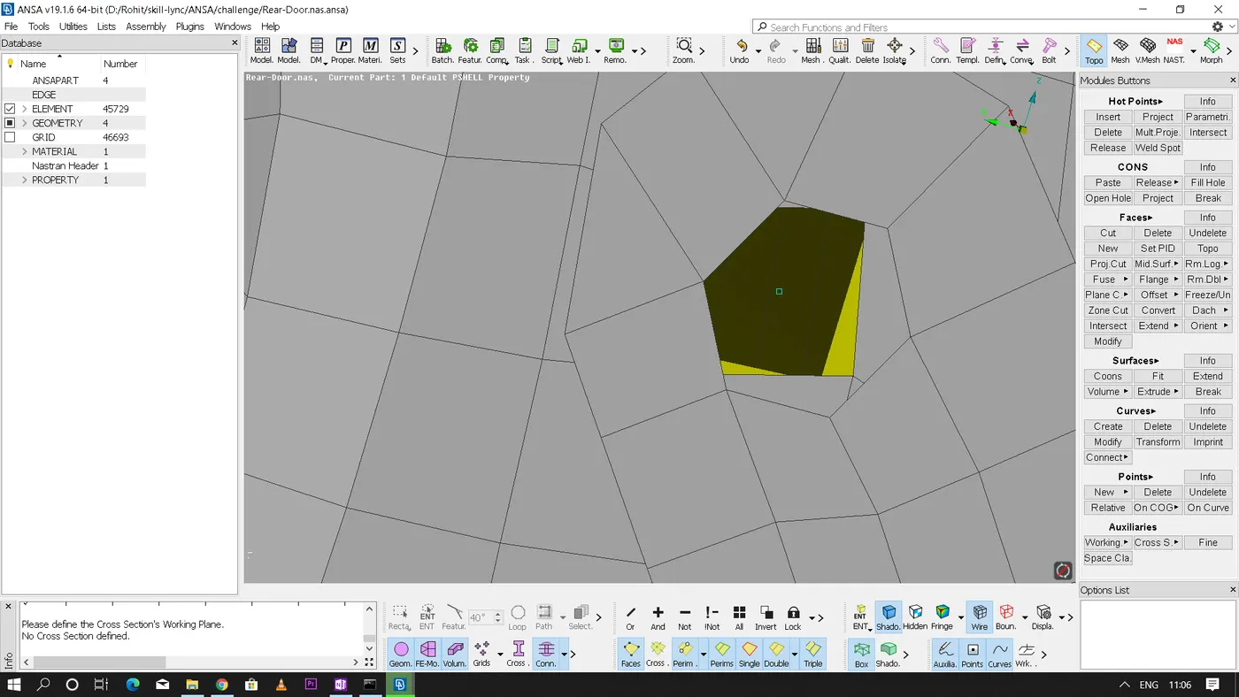
• Steps to be followed:
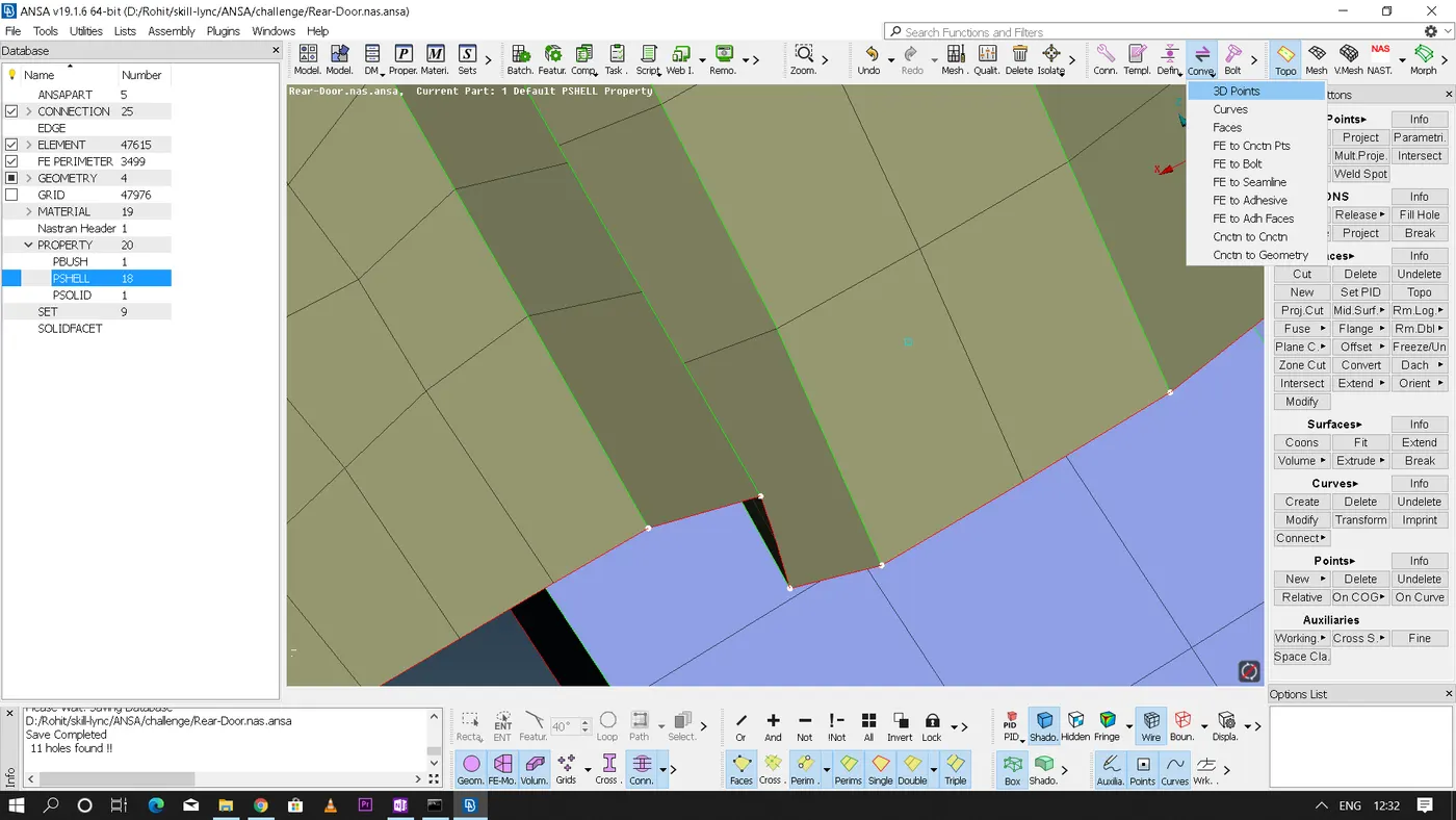
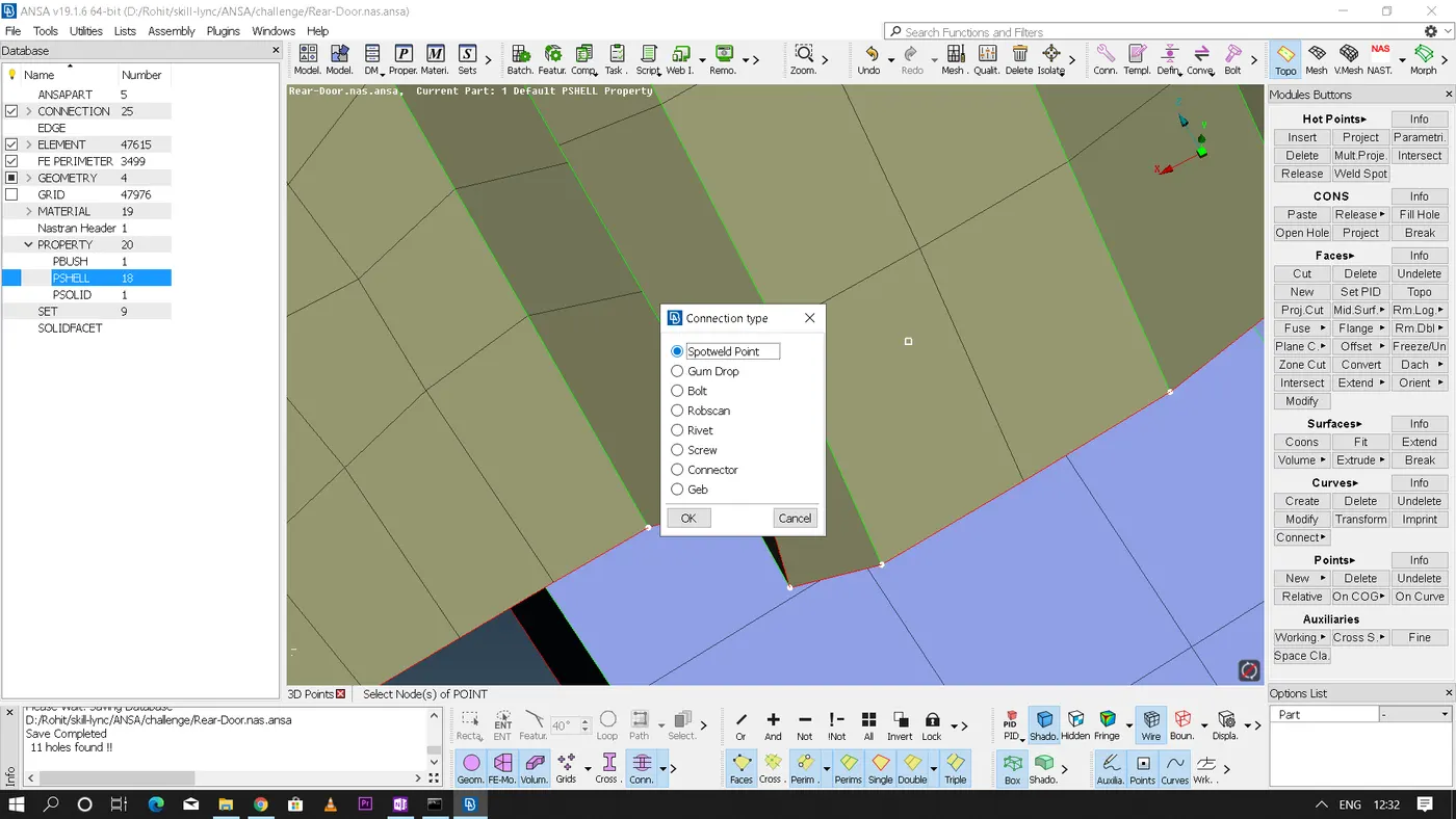
In assembly section - Convert - 3D point - Select the 3D point that has to be converted and middle click - select the feature to which it has to be converted here we select as bolt
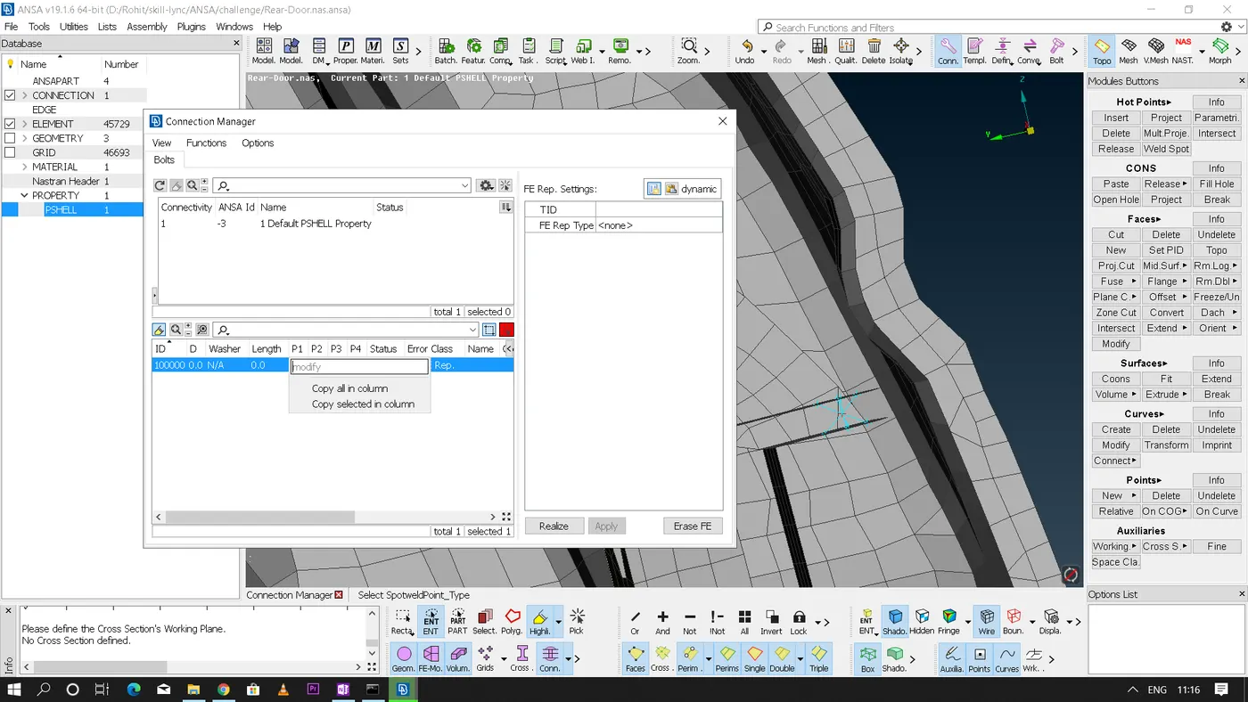
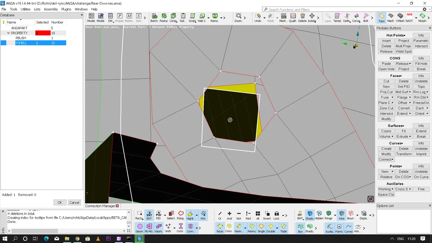
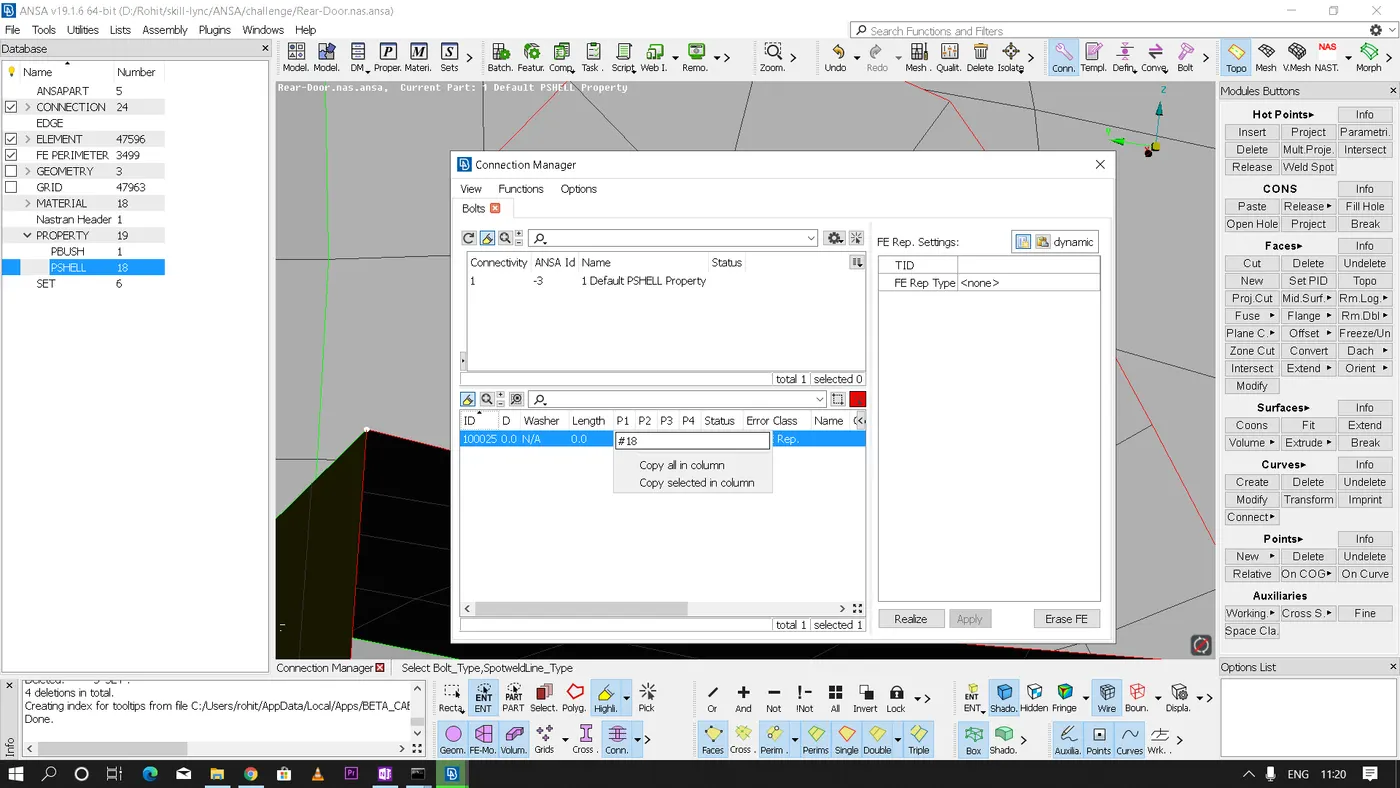
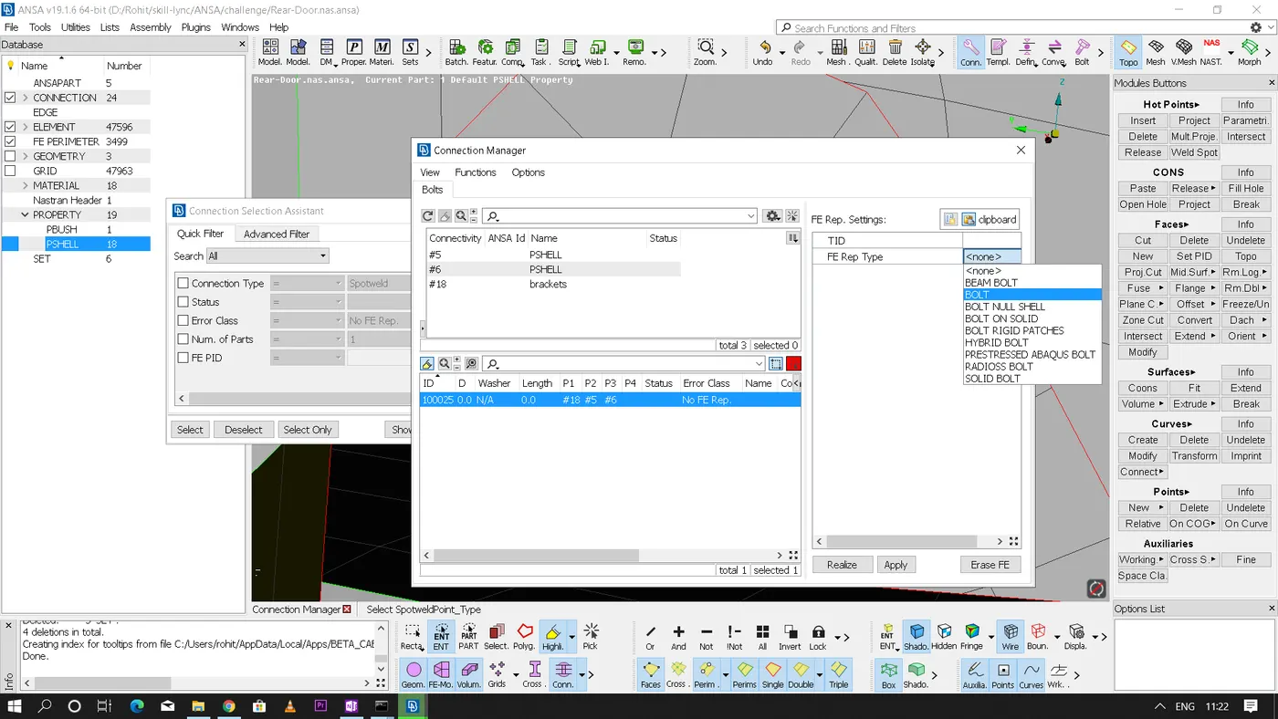
Now in connection manager - select the converted point - now assign the parts that has to be bolted individually to P1,P2,P3,P4 respectively - define the search distance which is user defined - select zone type that is required - now we can also select whether we need the bolt stem or not and we can also define the body type required - Now apply and realize to get the cluster of bolt feature.
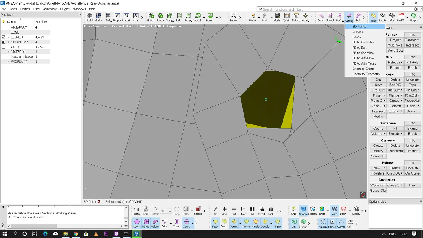
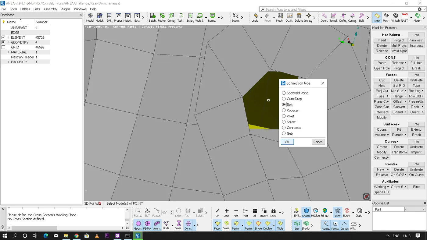
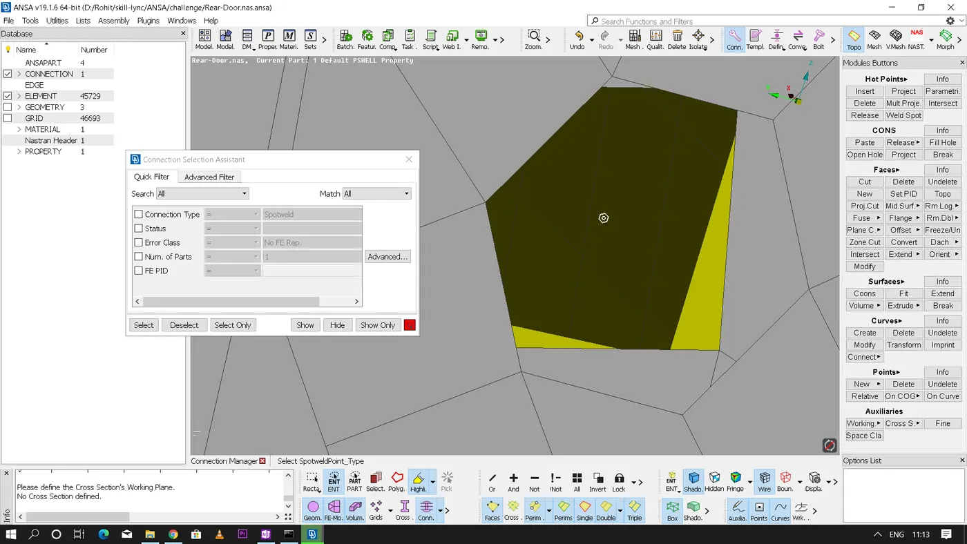
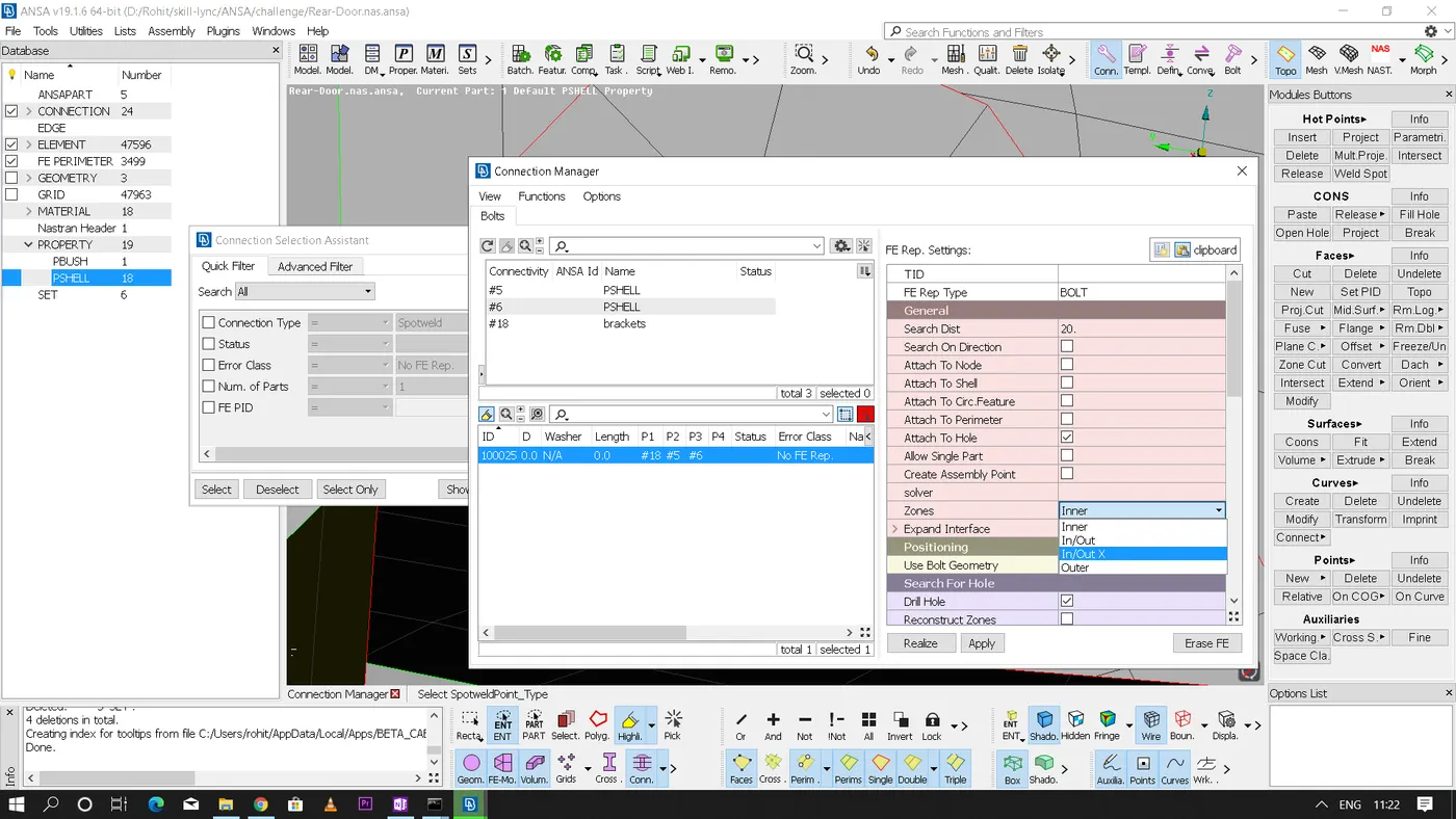
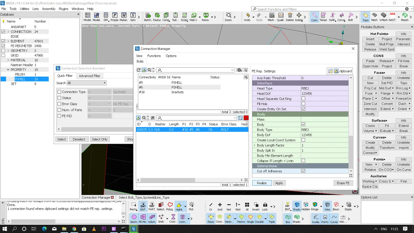
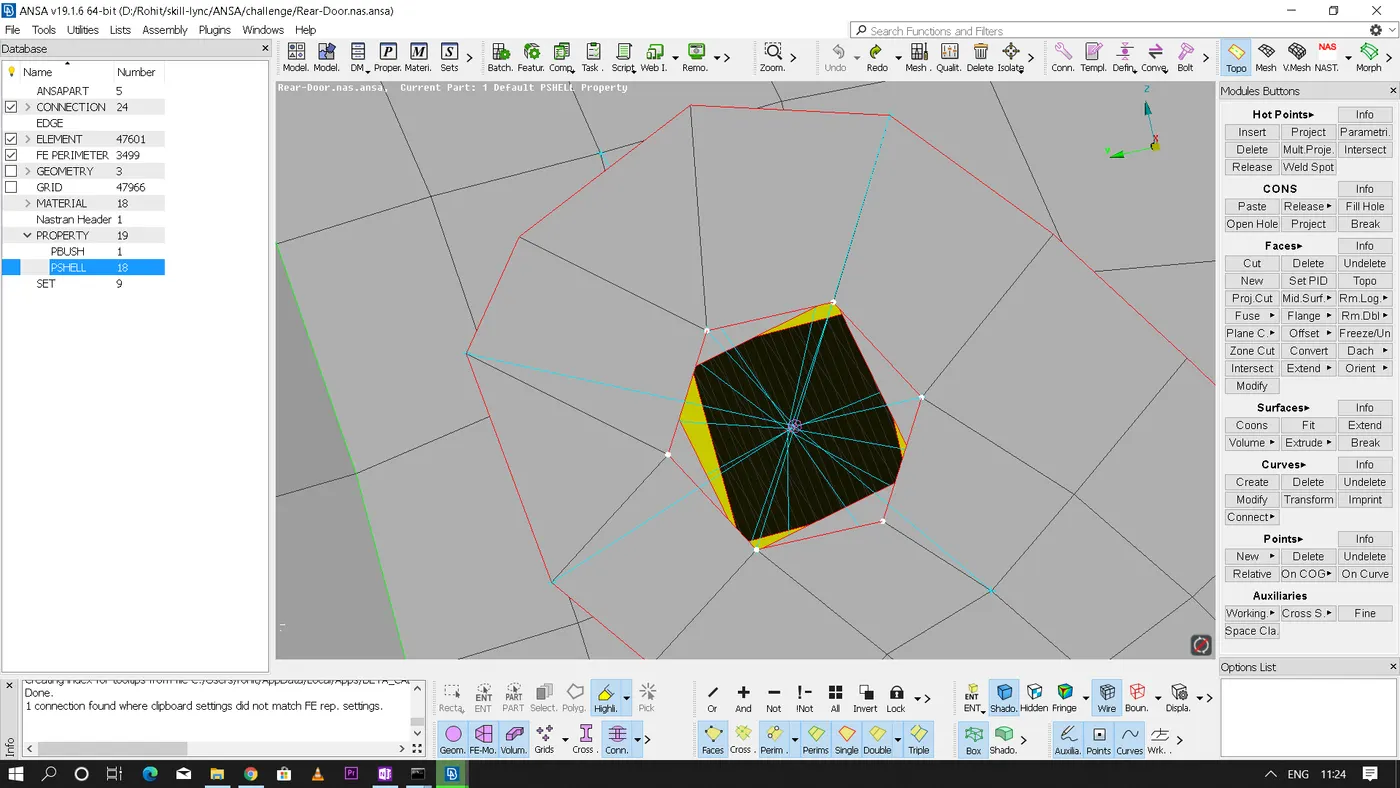
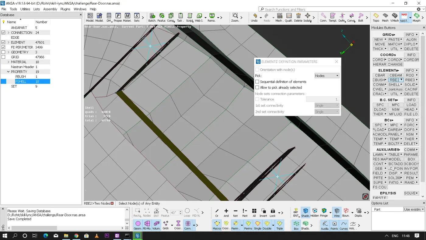
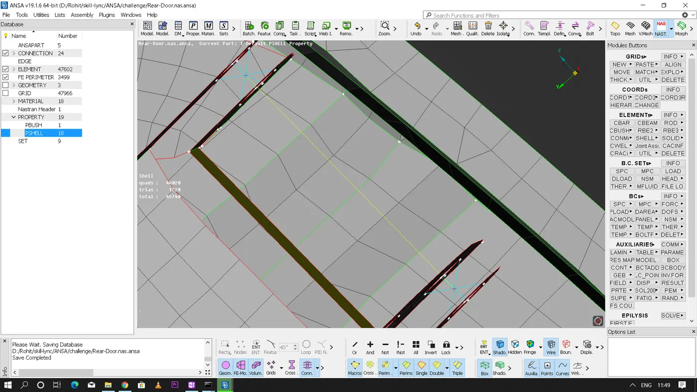
* Now for the door mechanism we cannot restrict in all 'DOF' because the door should be actuating in global 'Z' axis here for the opening and closing mechanism. Therefore the hinge created for the door mechanism should be restricted only in '12345' DOF only.
* The hinge is created with the help of RBE2 two node elements as shown.
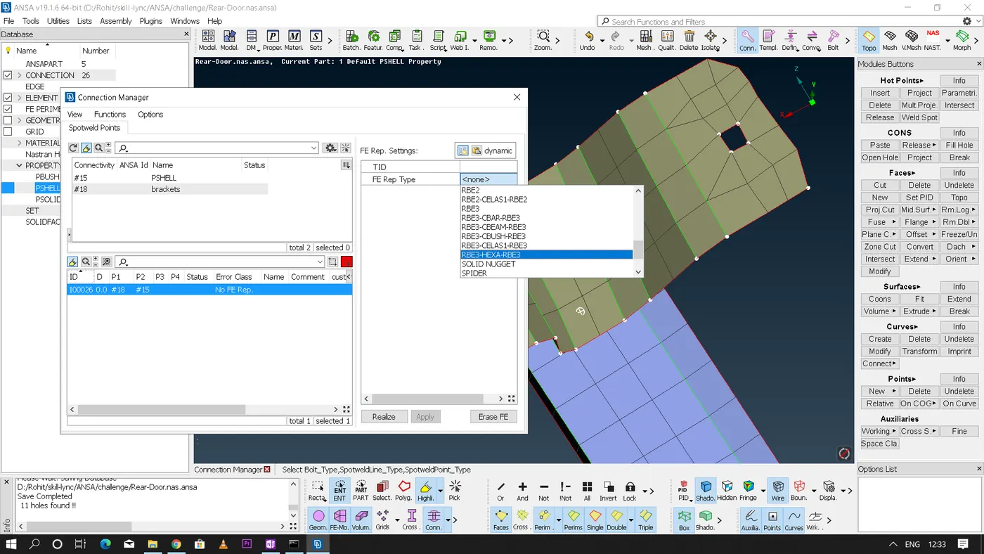
* Now for parts that has to be spot welded we need to create a 3D point using points - COG as we did in the above method and covert it into a 'Spotweld point' and then using connection manager select the spotweld point assign the parts that has to be welded(P1,P2..)
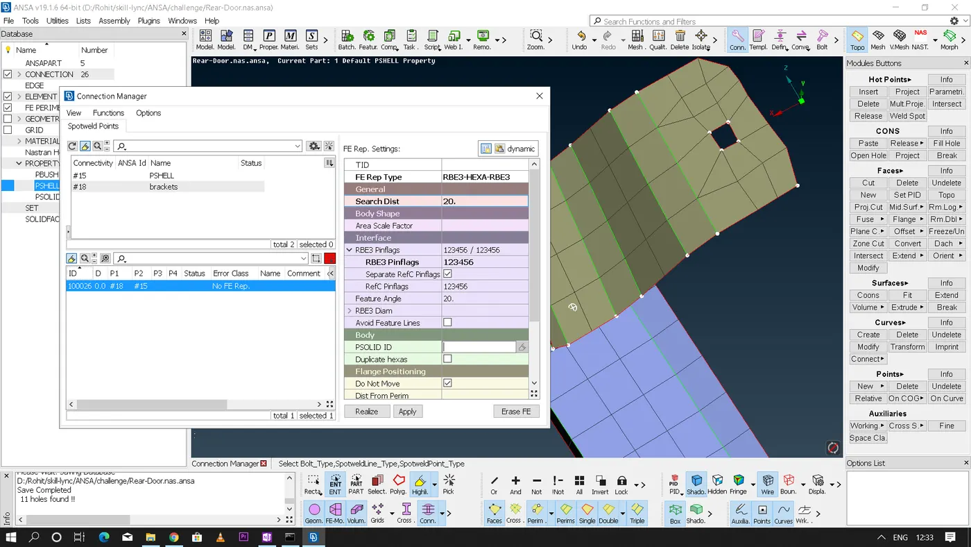
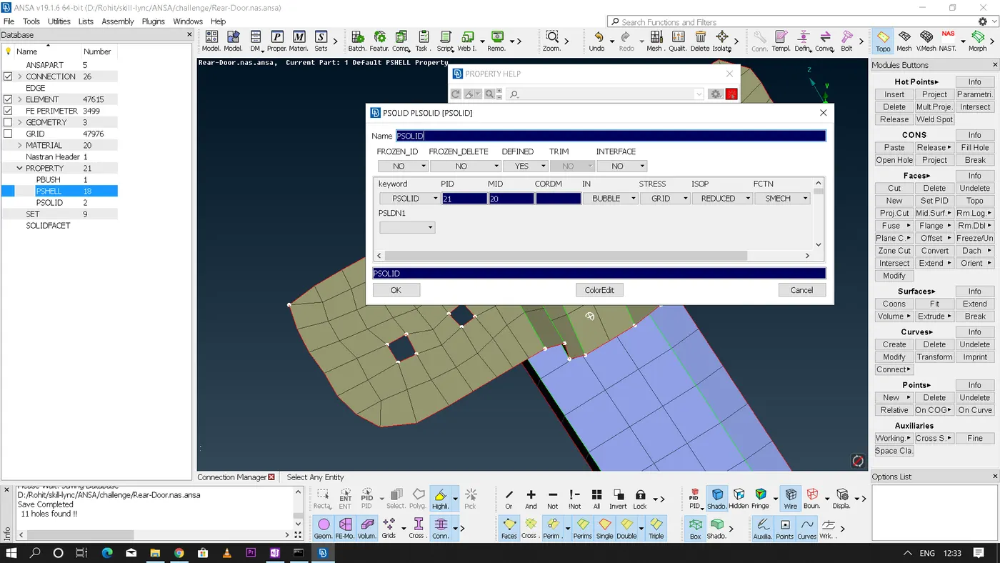
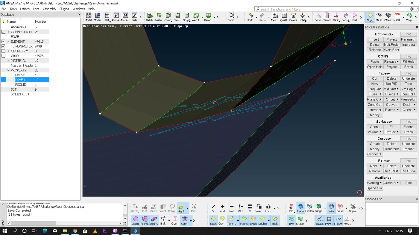
* In NASTRAN for this kind of spotwelds we use "RB3 - HEXA - RB3" FE Representation type, Set the Search distance - Make sure that RB3 pinflags are restricted in all 'DOF'(123456) - create a new PSOLID - apply and realize
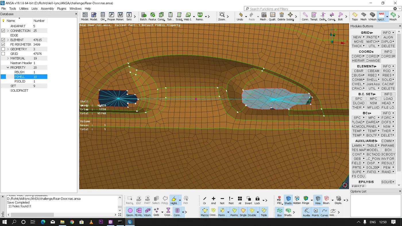
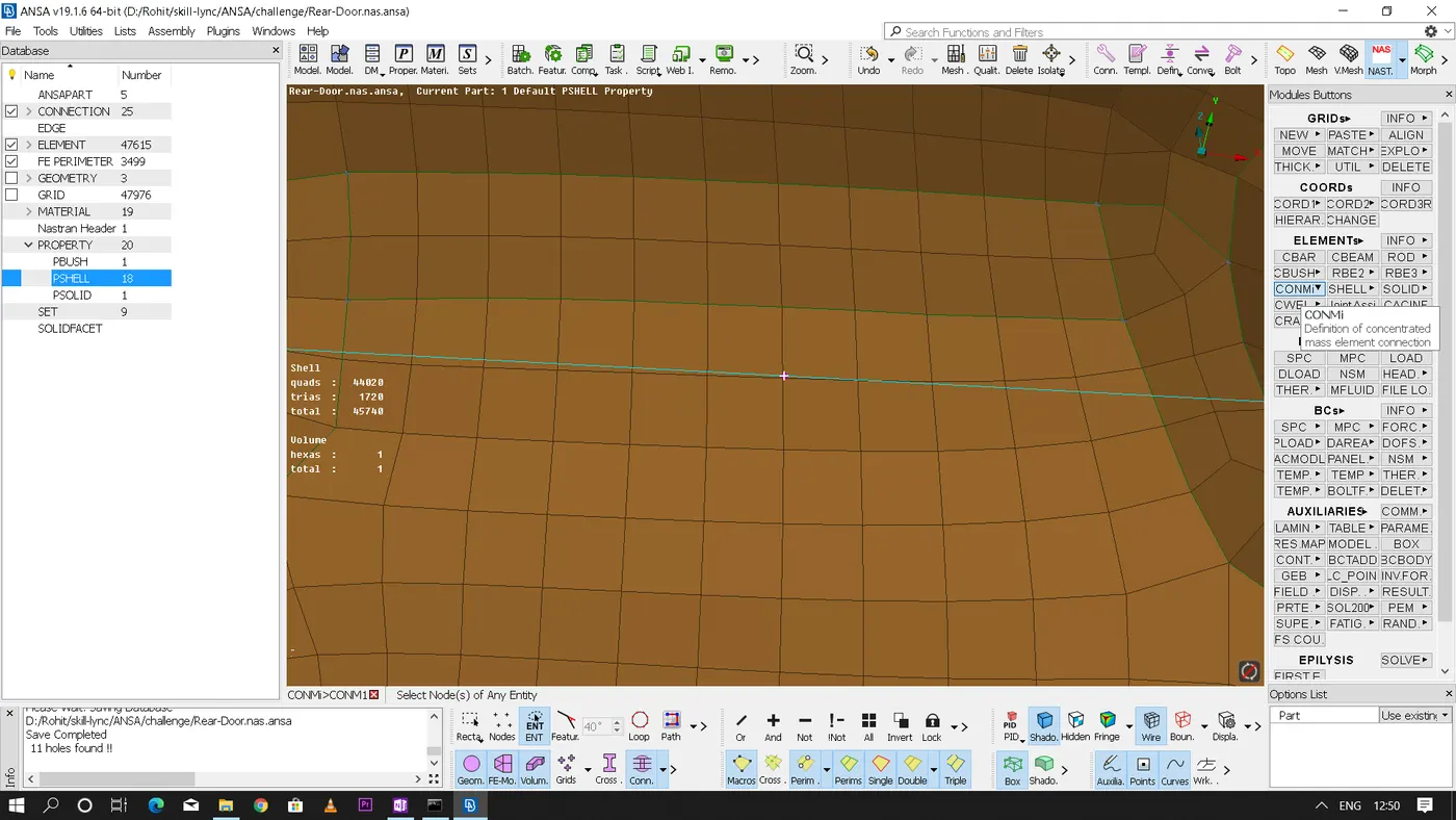
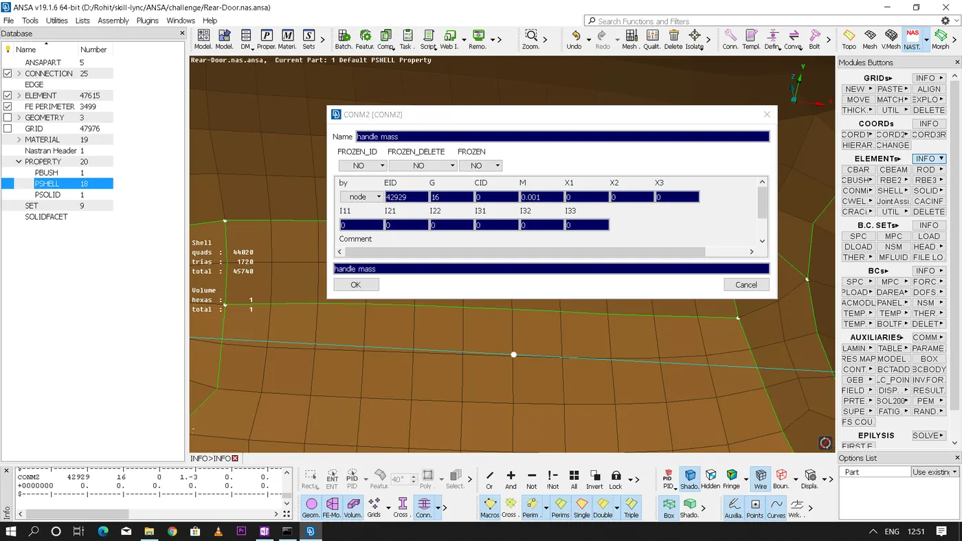
* In door we have many sub-mechanisms present and all those mechanisms are treated as masses while 'NVH' or 'NASTRAN' modelling. Therefore for example in door handle after rigidizing and connecting the 2 holes of the handle we need to connect them with 'RBE2' and at the 'COG' of the node should be converted into a 'Conmass' which is denoted as "ConMi" in elements section of ANSA and here we need to give the mass(M) value by creating a new PID and the mass value should be given in the units of tonnes only.
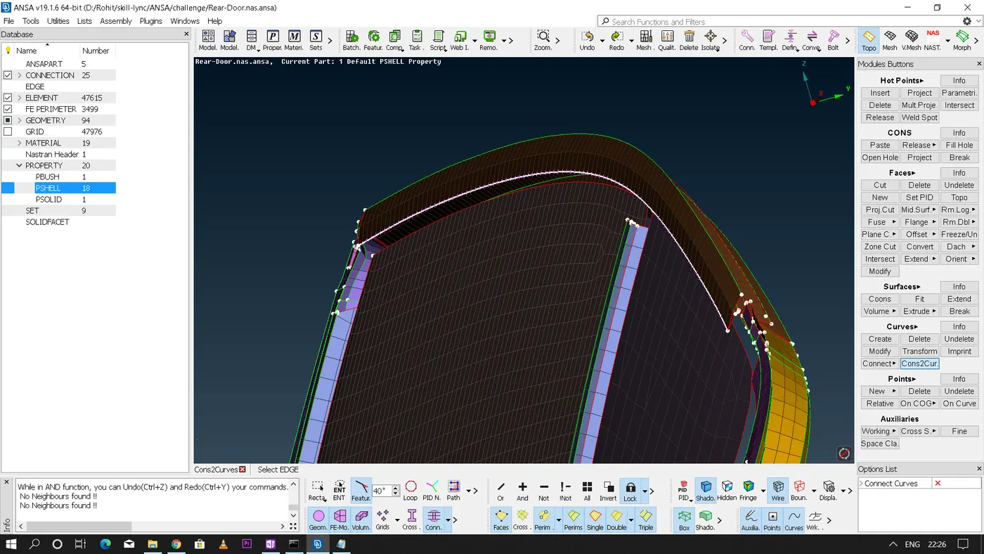
* In the door glass mechanism we have rubber gasket/weather strip present on all he sides of the window periphery for damping and now to define this feature we need to capture a gasket line which is nothing but the border of the nearest feature present to the glass part'
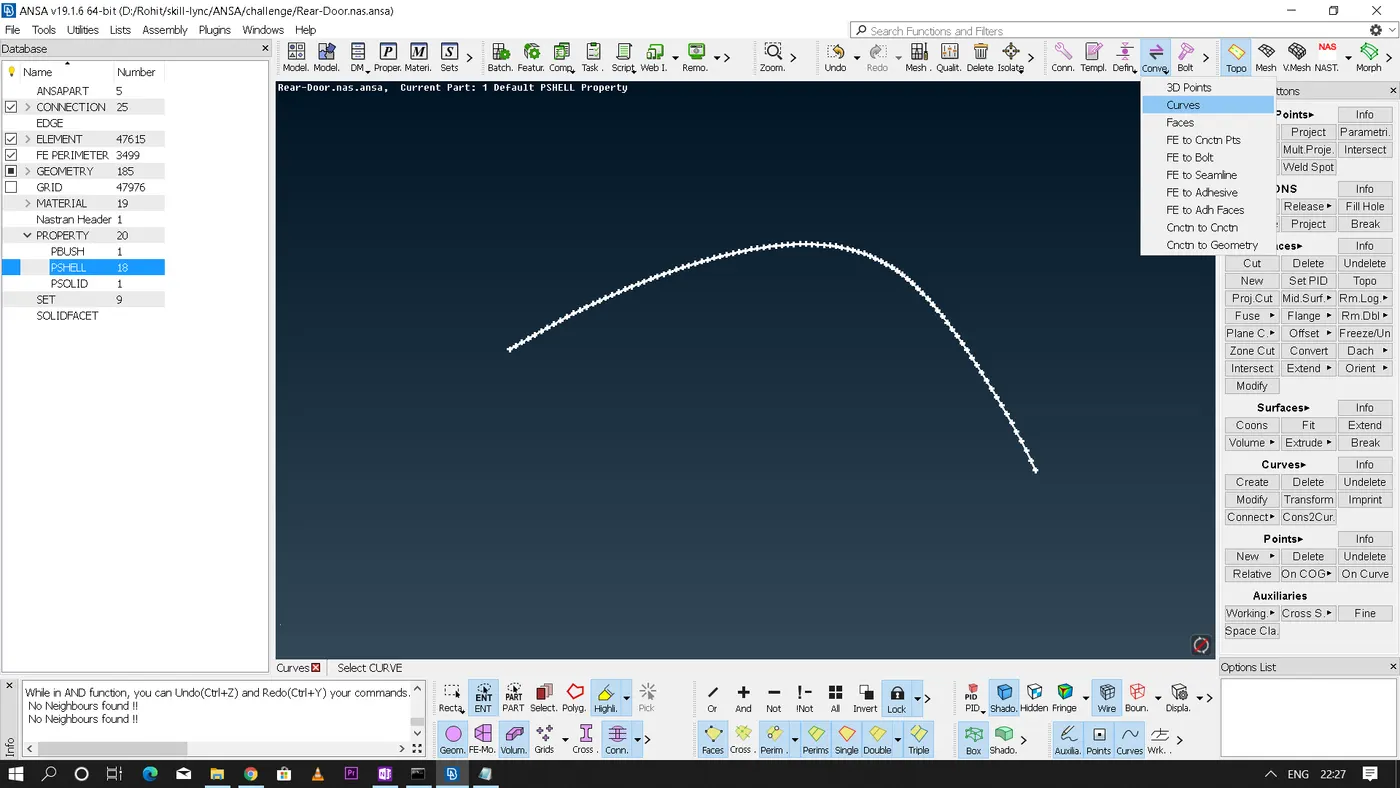
* Now by using 'Cons2curve' option convert those border lines into curves and then by using 'convert' option in the assembly section convert those curves into 'Spotline'.
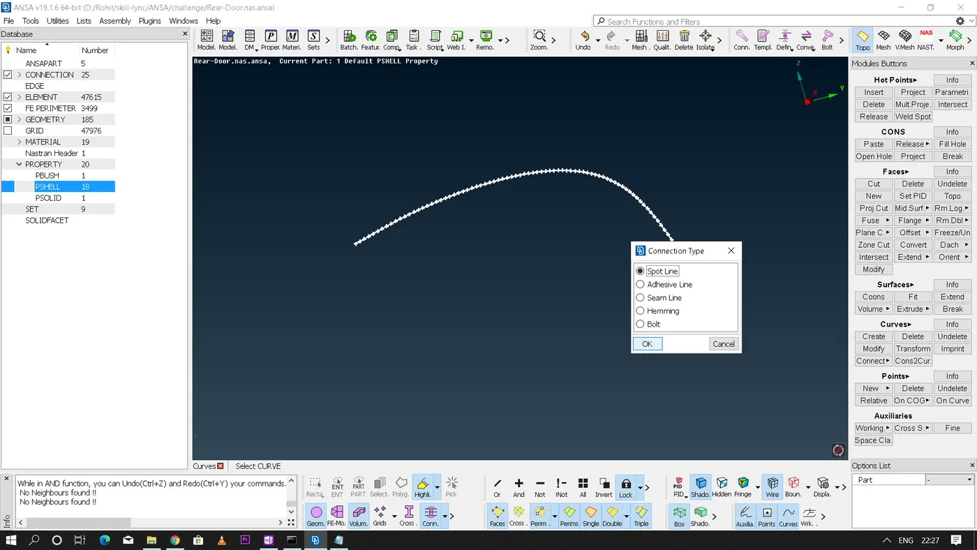
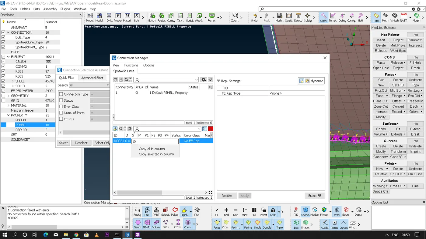
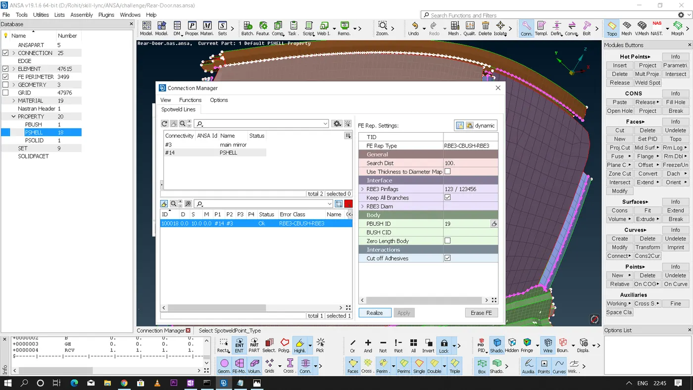
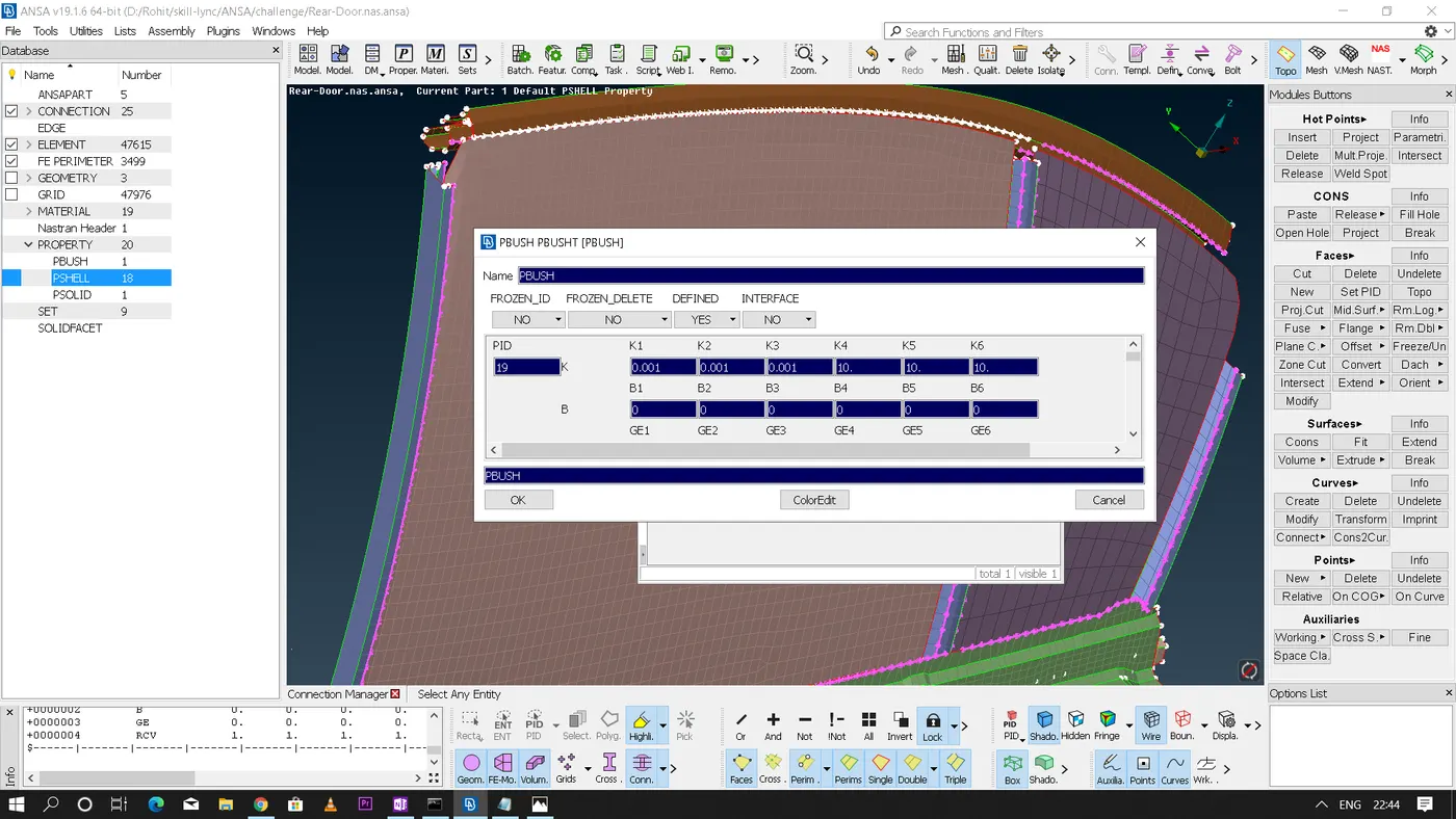
* Now using connection manager define the parts(P1,P2,..) - set 'S'(space between the two elements) as 10 - select 'FE rep type' as "RB3 - CBUSH - RB3" - set the search distance a bit more since the space between the parts is very large here - check mark the 'keep all branches' option - create a new 'PBUSH ID' here we need to key in the "K- coefficient of stiffness" values which will be predefined - Now we need to apply and realize.
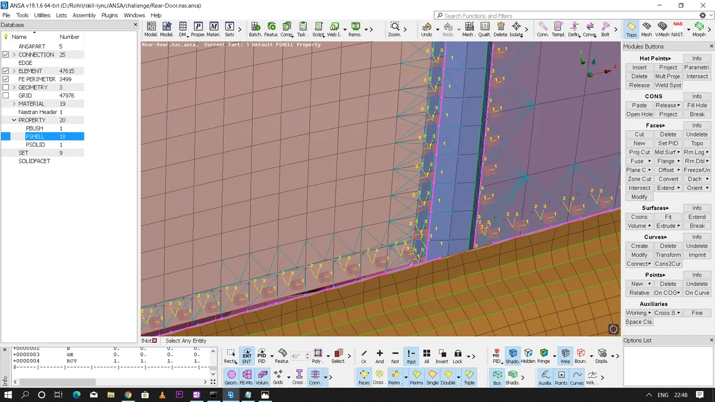
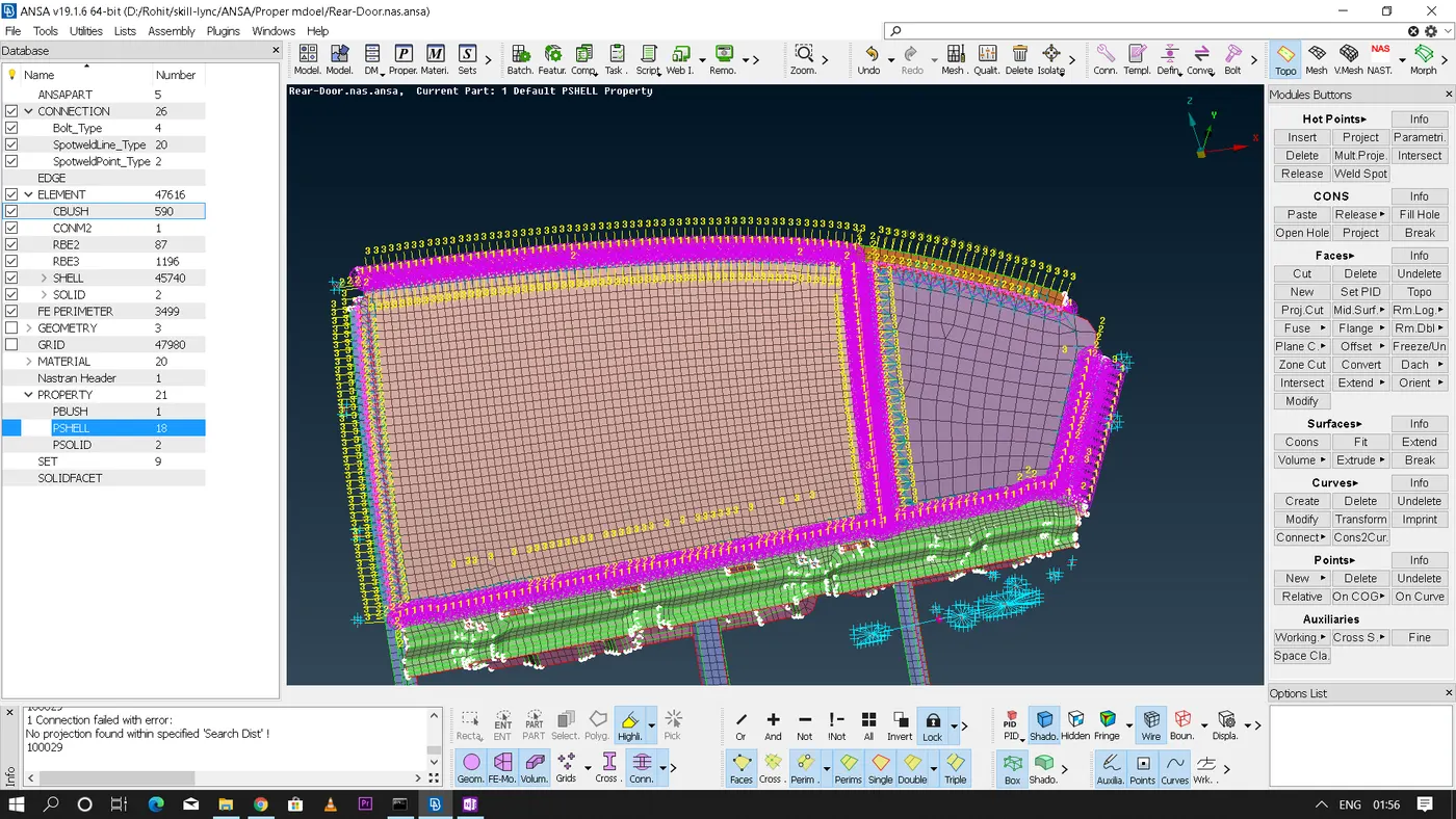
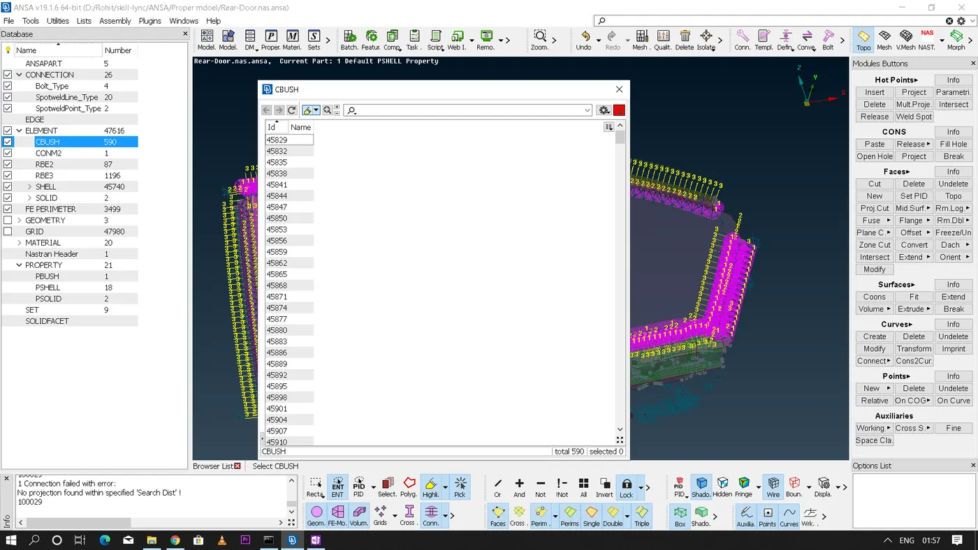
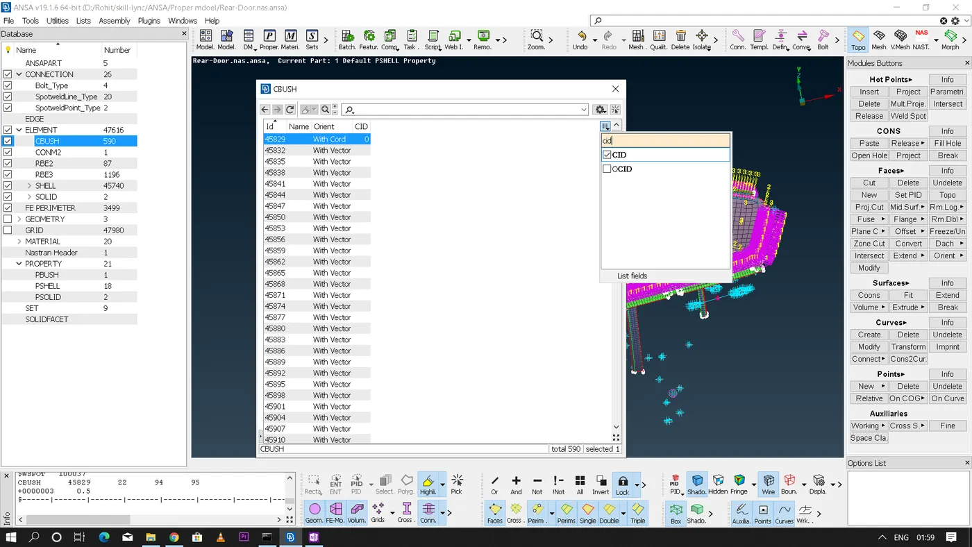
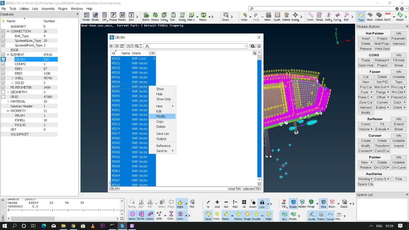
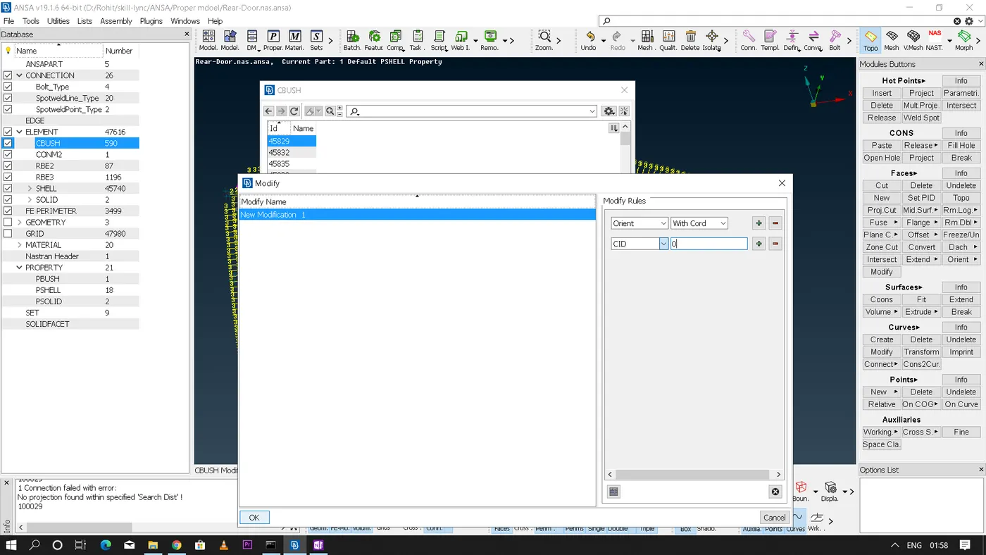
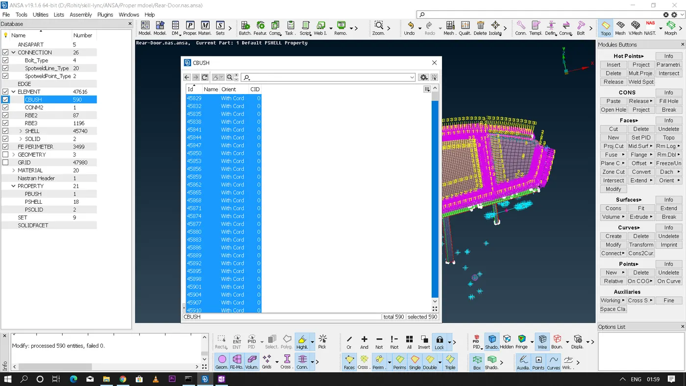
* For 'CBUSH' elements there will be a separate PID assigned for each and every spring elements and now we need to change the orientation of every element from 'with vector' to 'with cord' and the 'CID' to 0(zero) that means the local coordinates of the springs are now assigned to the global coordinate of the door.
* Link of the final model:
https://drive.google.com/file/d/1xih39IG9bMqo9BHwqGh4JgMzSdP4JeWa/view?usp=sharing
* Conclusion:
Hence the connections are deployed where ever required on the given rear door model. This challenge gave me a good practise on NASTRA(NVH) modelling.