Week 5 Sphere pressing on a plate
ANALYSIS OF SPHERE PRESSING ON A PLATE:
AIM:
To perform the analysis to simulate the sphere pressing on a plate, it will be observed that the plastic will get deformed and comparision can be done on that basis.
ANALYSIS SETUP FOR SPHERE PRESSING ON A PLATE:
I. GEOMETRY:
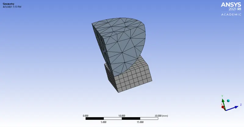
The CAD model of sheet metal is imported in Ansys static structural environment. It comprises of two different components named as sphere and plate. It is based on principle that, when the force exerted on sphere, then the plate gets deformed and it will show its non-linear nature by deforming to its limit.
II. MATERIALS:
Below are the materials which is used to perform analysis for the operation. The analysis is carried out for sphere and plate material respectively.
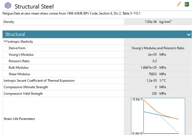
Sphere- Structural steel
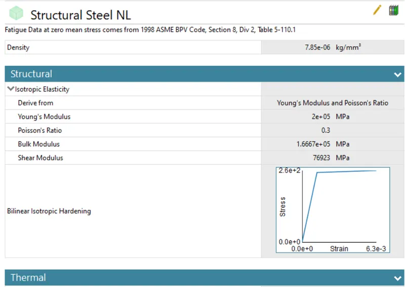
Plate- Structural steel (Non-linear)
The details of each component are to be shown in the figures below:
III. CONNECTION DETAILS:
Frictional-Sphere to Plate:
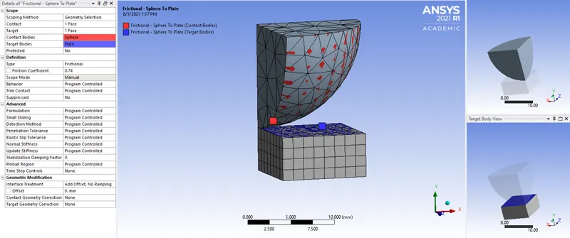
Frictional contact is given below between faces of sphere and plate as shown in the image below. The 1 face of sphere came in contact with 1 face of plate with a frictional coefficient of 0.74. Lastly, interface treatment in geometric modification is assigned as 'Add offset, No Ramped effects.'
IV. SYMMETRY:
A. Symmetry Region 1:
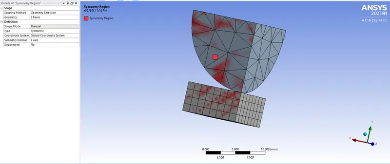
In this option, we have selected 2 faces of sphere and plate as their geometry selection. Their type will be defined as Symmetric and their symmetry normal had set to Z-axis across global coordinate system.
B. Symmetry Region 2:
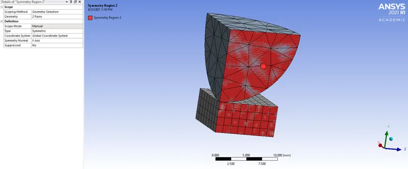
In this option, we have selected 2 faces of sphere and plate as their geometry selection. Their type will be defined as Symmetric and their symmetry normal had set to X-axis across global coordinate system.
V. MESH:
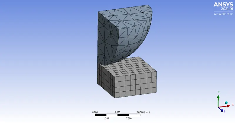
Basically, we have preferred default mesh for the analysis of plate body and outer surface of sphere.
VI. BOUNDARY CONDITIONS AND ANALYSIS SETTINGS:
A. ANALYSIS SETTINGS:
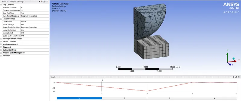
For this analysis the number of steps is set to 4 with Auto Time stepping is program controlled. After that, the solver type is to be Direct and then Large deflection is set to On, so as to account for change in stiffness due to change in shape of gears.
B. BOUNDARY CONDITIONS:
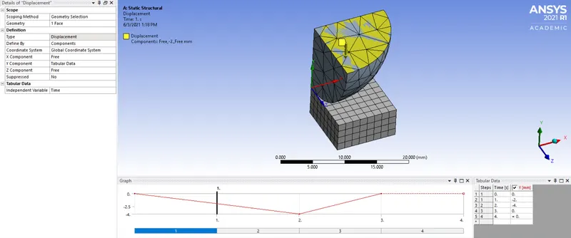
1. Displacement:
Basically, we have to select the face on sphere as geometry. Then, its type is considered as displacement and then its Y axis get's value from tabular form. Then, its value is ploted around graph.
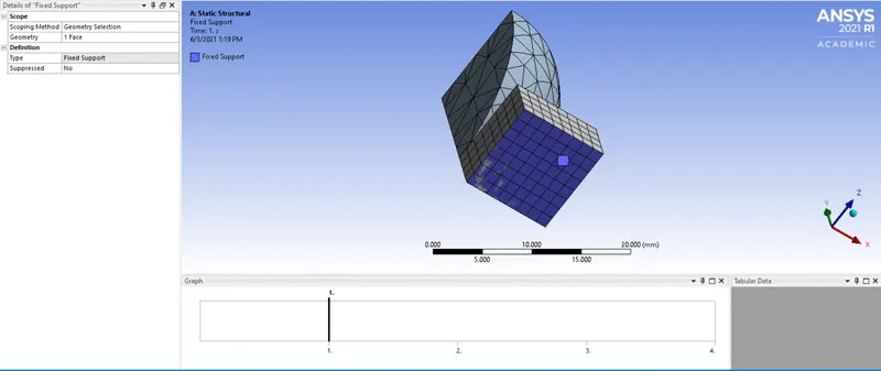
2. Fixed Support:
As, we have to select the bottom face of plate as its fixed support to its geometric selection. Therefore, the plate will not moved when the force gets applied on sphere.
VII. POST-PROCESSING RESULTS:
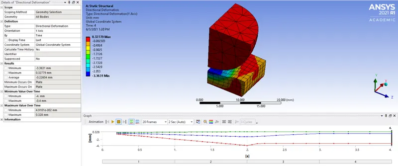
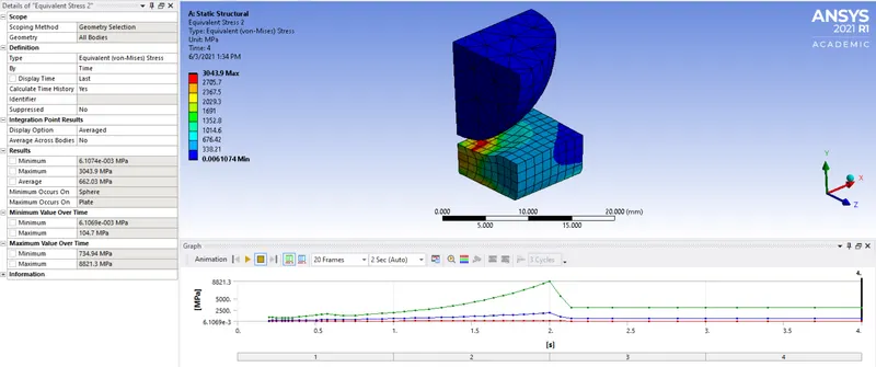
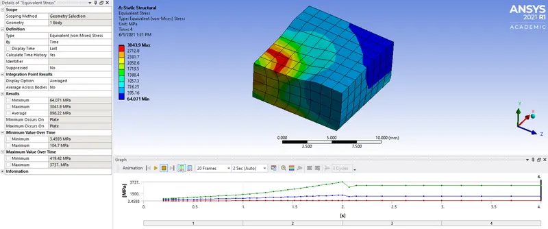
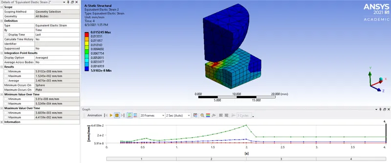
Now, we have to compare the deformation and stress on the basis of different materials. Then, we have to analyze the result for Directional deformation, equivalent elastic strain and equivalent stress for sphere operation. The results are as shown below:
I. DIRECTIONAL DEFORMATION:
II. EQUIVALENT STRESS FOR SET-UP AND PLATE:
III. EQUIVALENT ELASTIC STRAIN FOR SET-UP AND SPHERE:
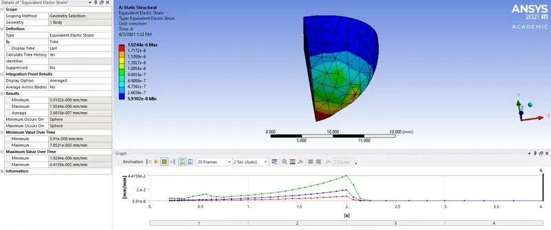
VIII. POST-PROCESSING SUMMARY:
|
Parameters |
Sphere on a plate operation |
|
Maximum Deformation |
0.32779 mm |
|
Minimum Deformation |
-3.3631 mm |
|
Maximum Equivalent elastic strain for plate |
1.5245e-002 mm/mm |
|
Minimum Equivalent elastic strain for plate |
5.9102e-008 mm/mm |
|
Maximum Equivalent stress for sphere |
3043.9 MPa |
|
Minimum Equivalent stress for sphere |
6.1074e-003 MPa |
CONCLUSION:
Hence, the overall structural analysis to simulate the sphere on a plate with a deformation of 4 mm is performed and proved.