Week 3
Aim:-
To determine the component checks for geometrical errors and providing good mesh flow for each elements in the model by satisfying above all given criteria with a thickness assignment from shell to solid. Additonally, below requirements also should be satisfied respectively.
- OFF elements after enabling criteria should be zero.
- Cyclic quads and opposite trias should be diminished from model.
- Good mesh flow.
Procedure:-
1. Open the ANSA Software.
2.Click on the downloaded Hood model and open it.
3.As the model will appear. Use the command 'TOPO'(Faces~TOPO) and do window selection for all the model.
- After the TOPO cleanup, then we have to check the geometrical errors for further steps of MID-Surfacing.
- Firstly, we have to click on the 'Geometry' in the Checks manager(Tools~Checks~Geometry), then an Auto-generated template will be occured.
- Secondly, after displaying the template, likewise we have to click on the 'Execute' option in the template which will displayed the status of error visibility.
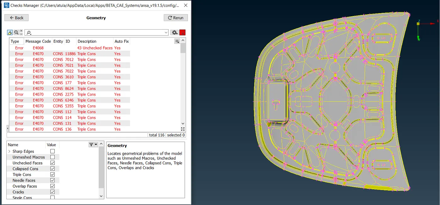
- Then, after displaying errors, we can 'auto-fix' this error. Select all the errors and by right clicking 'fix' option will be generated and by click on it auto-fix error will automatically be resolved. After, auto-fixing this error some of the errors should be fixed by our own. Thus, these errors should be resolved one after another. For this, we have to use 'Hybrid Not'(Bullens~Hybrid Not) option.
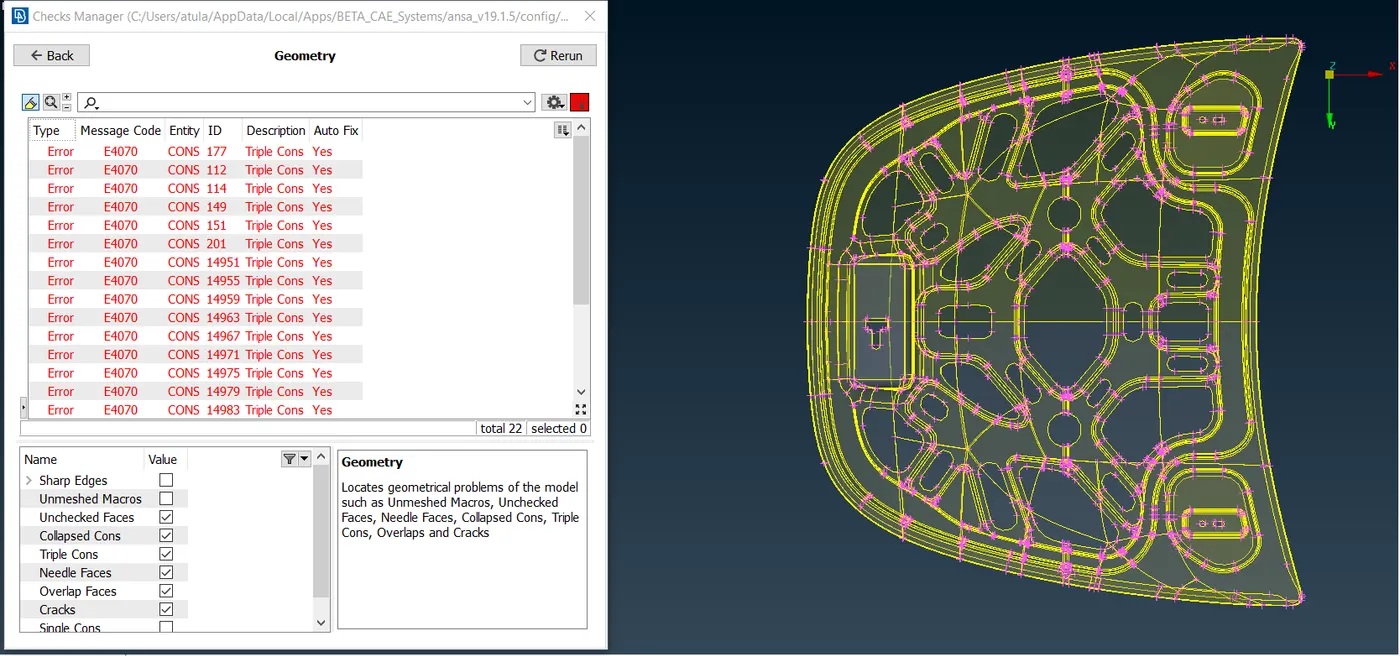
- Admittedly, these errors should be resolves sequence by sequence, so click on error and go to the option 'show only' then the error will be displayed. Likewise, go to Release(CONS~Release) option, then by clicking on it and doing window selection of TOPO in faces, our error will be resolved respectively. Similarly, we have to resolved all errors one by one.
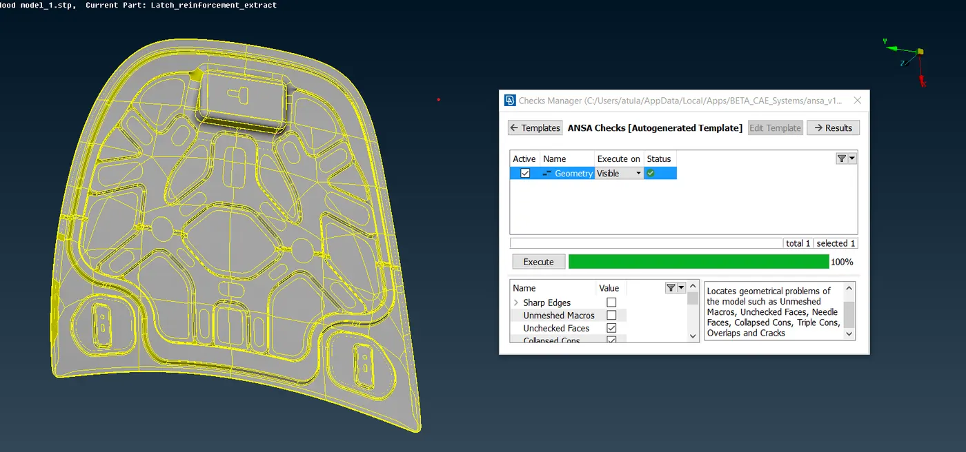
- Thus, when all errors are resolved, then in template it will shown geometry check status as 100% which clarify that our geometrical errors along with TOPOLOGY clean up is all up to the mark.
- Therefore, our geometry is now ready for MID-Surfacing.
4. Our geometry is now undergo through MID-Surfacing. Basically, we preferred mid-surfacing to get a better mesh flow by converting solid to shell(2-D). Now, for mid-surfacing we have to 'Set PID(Part ID)'(Ctrl+P) for each elements of the model. Accordingly, we have to set various colour orientations for each elements in the model. Now, different elements is showed below:-
I:-Inner Hood
-
- Select on inner hood and by right clicking to 'show only' option, it will depicts the inner hood.
- Now, we have to do mid-surfacing. Here, we can use option 'Auto Mid-surfacing'(Faces~Mid-surfacing~Skin). By doing window selection and by clicking middle mouse button the automatic offset will be generated and then our mid-surface for inner hood will be appeared.
- Now, our FE Model, is now ready for meshing. Before that, we need to follow some protocols, likewise primarily one of its distance between nodes at perimeter and macros. We have to measure distance and like, we have focus to attain a same distance between nodes as well as cons.
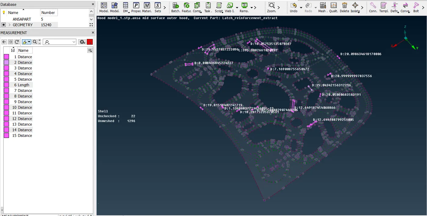
- Basically, we need to assign constant distance, so we need to use 'Length'(Perimeters~Length)option and we have to assign average thickness '5 mm' as perimeter and macros. Then our FE Model have constant distance. Likewise, two protocols also we have follow i.e. 'Number'(Perimters~Number) and 'Slide'(Perimeters~Slide). Now, our model is ready for meshing.
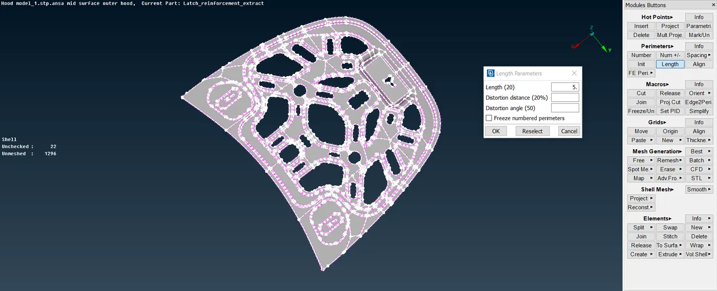
- Additionally, we have to move towards meshing. Primarily, we have prefered 'Best'(Mesh generation~Best) mesh option for meshing. Similarly, we have to do meshing as part by part so we need to make Project cut(Macros~Project Cut) to divide the surface and likewise, we have to do the mesh as part by part.
- Before that, we have to set mentioned quality criteria as per given data. So, click 'F11' a template will be generated, then we have to select required quality parameters as per assigned. Then, for same we have to click 'Presentation Paramters' in the template and we have to click on the 'elements' option and we have to show the same 'Demand effect' arrow.
- After that, we have to click 'Mesh'(Utilities~Mesh) option and we have set to average, maximum and minimum length. Then, we have to do best mesh one part after another. Simultaneously, we have to use two commands 'Reconstruct'(Shell mesh~Reconstruct) and 'Smooth'(Shell mesh~Smooth). For reducing trias and Off elements we have to use basically five commands namely, Split(Elements~Split), Paste(Grids~Paste), Join(Elements~Join), Num+/-(Perimeters~Num+/-), Swap(Elements~Swap).
- As, inner hood is symmetrical type of element, so we do mesh on only one side, likely, we can do symmetry on other side. Then, after completing mesh flow, we have to 'delete'(Utilities~Delete) one side and do "transform'(Utilities~transform~Copy~select entities~Default symmetry plane~node~Finish). Thus, our element will appeared in meshing.
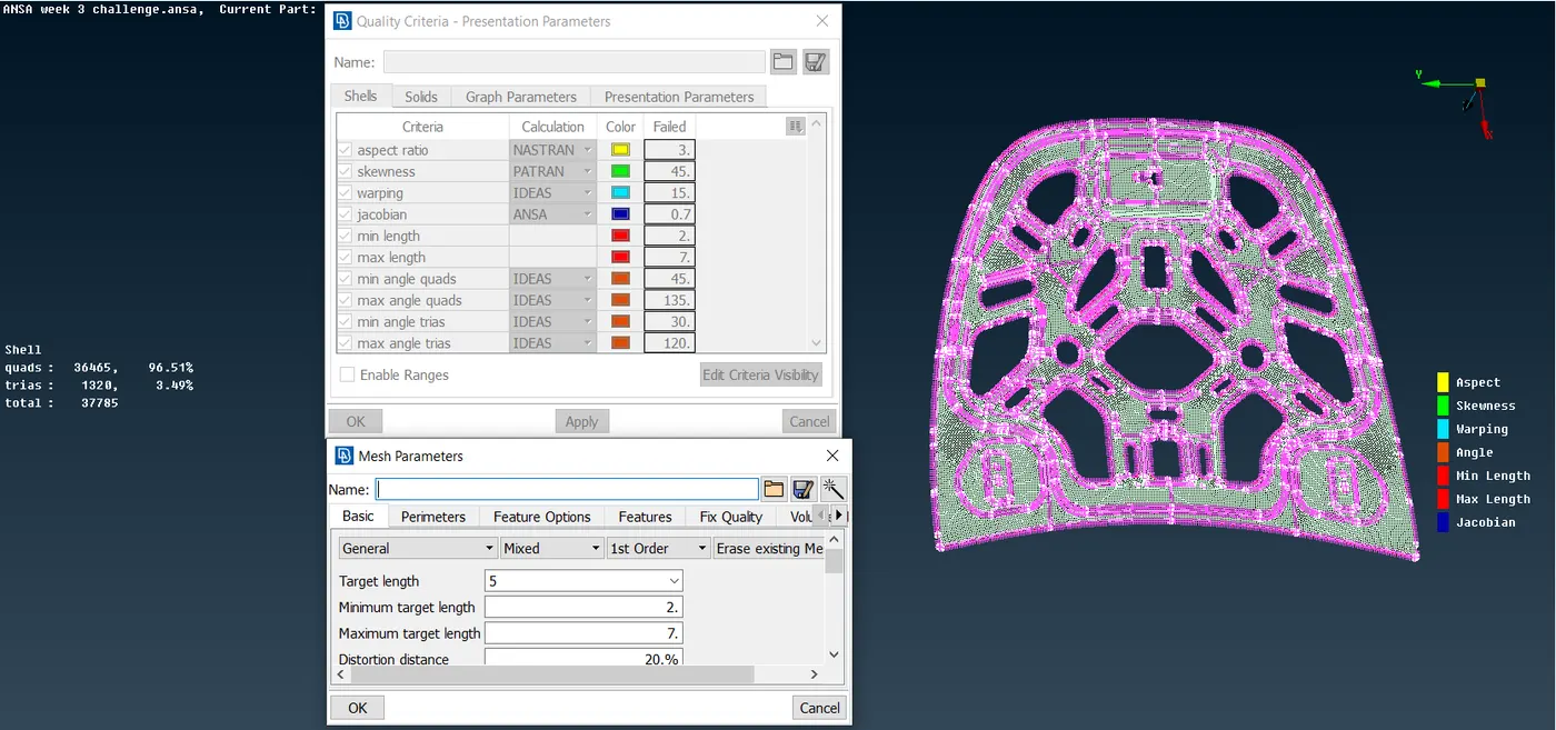
- Thus, our objective is achieved. So, inner hood mesh model can be viewed in 'PID' mode for its colour orientation.
II. Outer Hood:-
- Select on outer hood and by right clicking to 'show only' option, it will depicts the outer hood.
- Now, we have to do mid-surfacing. Here, we can use option 'Manual mid-surfacing'(Offset~Faces). Here, we can't do Auto-midsurfacing as variable thickness is present over the surface. So, likewise, inner hood, outer hood is also symmetrical element. Then, click on the top surface with 'feature' command and measure the thickness simultaneously and give offset for that surface, manual mid-surface will be generated.
- Now, our FE Model, is now ready for meshing. Before that, we need to follow some protocols, likewise primarily one of its distance between nodes at perimeter and macros. We have to measure distance and like, we have focus to attain a same distance between nodes as well as cons.
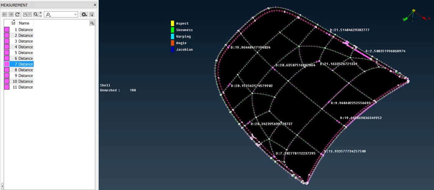
- Basically, we need to assign constant distance, so we need to use 'Length'(Perimeters~Length)option and we have to assign average thickness '5 mm' as perimeter and macros. Then our FE Model have constant distance. Likewise, two protocols also we have follow i.e. 'Number'(Perimters~Number) and 'Slide'(Perimeters~Slide). Now, our model is ready for meshing.
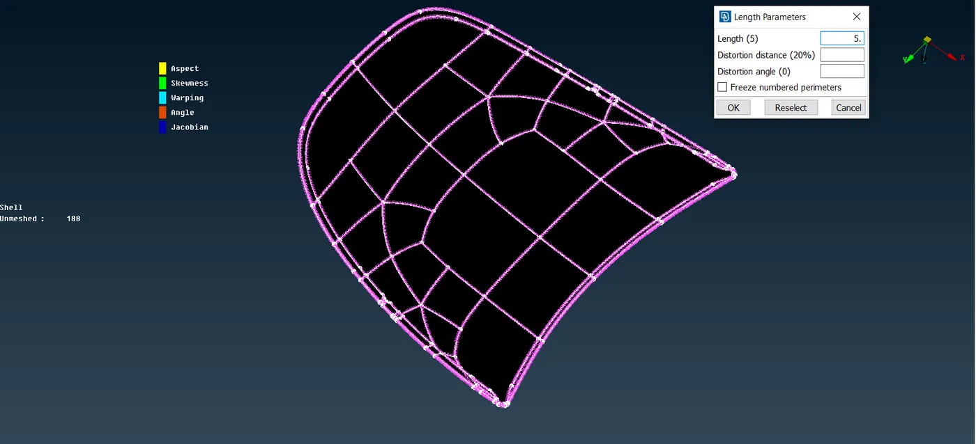
- Additionally, we have to move towards meshing. Primarily, we have prefered 'Best'(Mesh generation~Best) mesh option for meshing. Similarly, we have to do meshing as part by part so we need to make Project cut(Macros~Project Cut) to divide the surface and likewise, we have to do the mesh as part by part.
- This point will be same as point 6. as inner hood.
- After that, we have to click 'Mesh'(Utilities~Mesh) option and we have set to average, maximum and minimum length. Then, we have to do best mesh one part after another. Simultaneously, we have to use two commands 'Reconstruct'(Shell mesh~Reconstruct) and 'Smooth'(Shell mesh~Smooth). For reducing trias and Off elements we have to use basically five commands namely, Split(Elements~Split), Paste(Grids~Paste), Join(Elements~Join), Num+/-(Perimeters~Num+/-), Swap(Elements~Swap).
- Then, after completing mesh flow, we have to 'delete'(Utilities~Delete) one side and do "transform'(Utilities~transform~Copy~select entities~Default symmetry plane~node~Finish). Thus, our element will appeared in meshing.
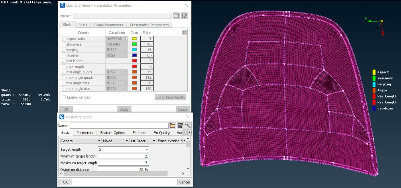
- Thus, our objective is achieved. So, inner hood mesh model can be viewed in 'PID' mode for its colour orientation.
III. and IV. Hinge I and II Reinforcement:-
- Select the Hinge reinforcement by right clicking to 'show only' option, it will depicts the Hinge reinforcement.
- This point will be same as point 2. as inner hood.
- Now, our FE Model, is now ready for meshing. Before that, we need to follow some protocols, likewise primarily one of its distance between nodes at perimeter and macros. We have to measure distance and like, we have focus to attain a same distance between nodes as well as cons.
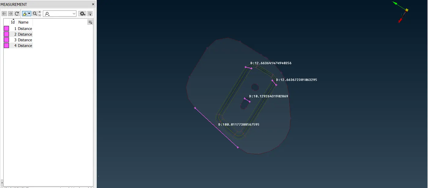
- Basically, we need to assign constant distance, so we need to use 'Length'(Perimeters~Length)option and we have to assign average thickness '5 mm' as perimeter and macros. Then our FE Model have constant distance. Likewise, two protocols also we have follow i.e. 'Number'(Perimters~Number) and 'Slide'(Perimeters~Slide). Now, our model is ready for meshing.
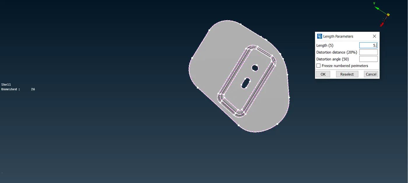
- Additionally, we have to move towards meshing. Primarily, we have prefered 'Best'(Mesh generation~Best) mesh option for meshing. Similarly, we have to do meshing as part by part so we need to make Project cut(Macros~Project Cut) to divide the surface and likewise, we have to do the mesh as part by part.
- This point will be same as point 6. as inner hood.
- After that, we have to click 'Mesh'(Utilities~Mesh) option and we have set to average, maximum and minimum length. Then, we have to do best mesh one part after another. Simultaneously, we have to use two commands 'Reconstruct'(Shell mesh~Reconstruct) and 'Smooth'(Shell mesh~Smooth). For reducing trias and Off elements we have to use basically five commands namely, Split(Elements~Split), Paste(Grids~Paste), Join(Elements~Join), Num+/-(Perimeters~Num+/-), Swap(Elements~Swap).
- Thus, our element will appeared in meshing.
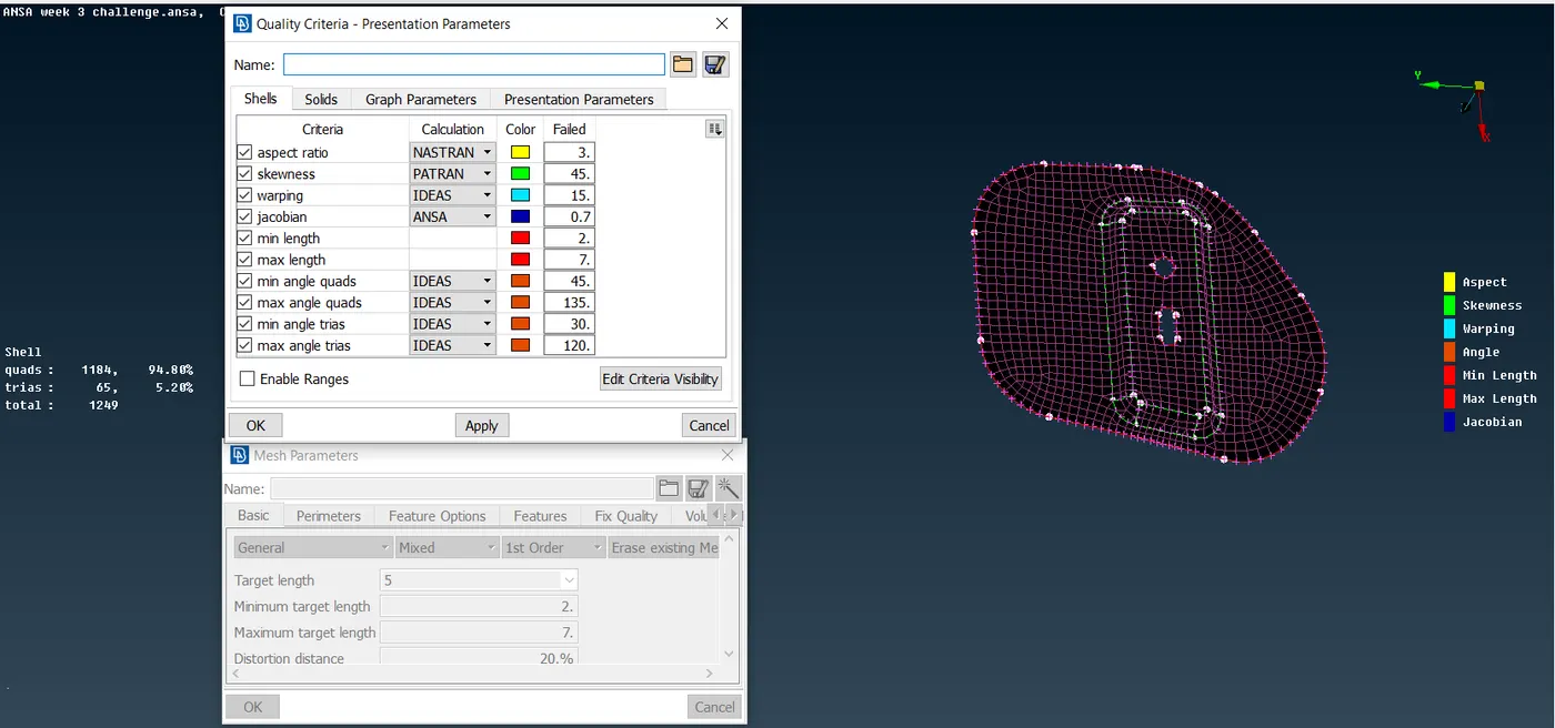
- Thus, our objective is achieved. So, inner hood mesh model can be viewed in 'PID' mode for its colour orientation.
V. Latch Rod Reinforcement:-
- Select on latch rod reinforcement and by right clicking to 'show only' option, it will depicts the Latch rod reinforcement.
- Now, we have to do mid-surfacing. Here, we can use option 'Auto Mid-surfacing'(Faces~Mid-surfacing~Skin). By doing window selection and by clicking middle mouse button the automatic offset will be generated and then our mid-surface for inner hood will be appeared.
- Now, our FE Model, is now ready for meshing. Before that, we need to follow some protocols, likewise primarily one of its distance between nodes at perimeter and macros. We have to measure distance and like, we have focus to attain a same distance between nodes as well as cons.
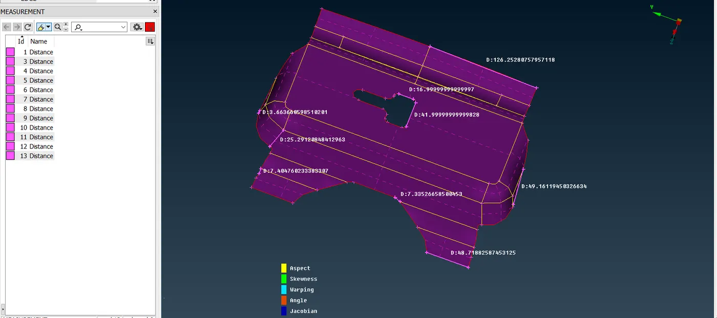
- Basically, we need to assign constant distance, so we need to use 'Length'(Perimeters~Length)option and we have to assign average thickness '5 mm' as perimeter and macros. Then our FE Model have constant distance. Likewise, two protocols also we have follow i.e. 'Number'(Perimters~Number) and 'Slide'(Perimeters~Slide). Now, our model is ready for meshing.
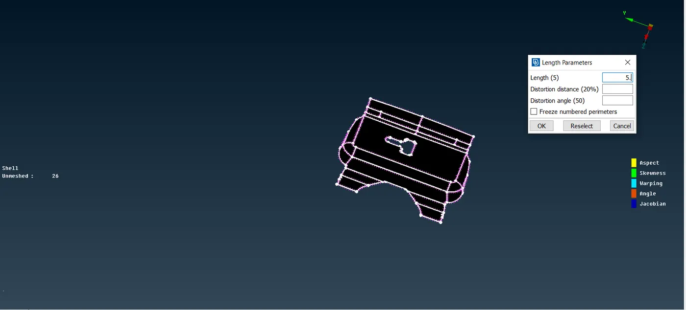
- Additionally, we have to move towards meshing. Primarily, we have prefered 'Best'(Mesh generation~Best) mesh option for meshing. Similarly, we have to do meshing as part by part so we need to make Project cut(Macros~Project Cut) to divide the surface and likewise, we have to do the mesh as part by part.
- This point will be same as point 6. as inner hood.
- After that, we have to click 'Mesh'(Utilities~Mesh) option and we have set to average, maximum and minimum length. Then, we have to do best mesh one part after another. Simultaneously, we have to use two commands 'Reconstruct'(Shell mesh~Reconstruct) and 'Smooth'(Shell mesh~Smooth). For reducing trias and Off elements we have to use basically five commands namely, Split(Elements~Split), Paste(Grids~Paste), Join(Elements~Join), Num+/-(Perimeters~Num+/-), Swap(Elements~Swap).
- Thus, our element will appeared in meshing.
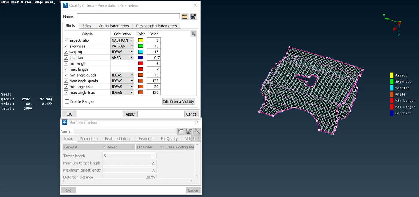
- Thus, our objective is achieved. So, inner hood mesh model can be viewed in 'PID' mode for its colour orientation.
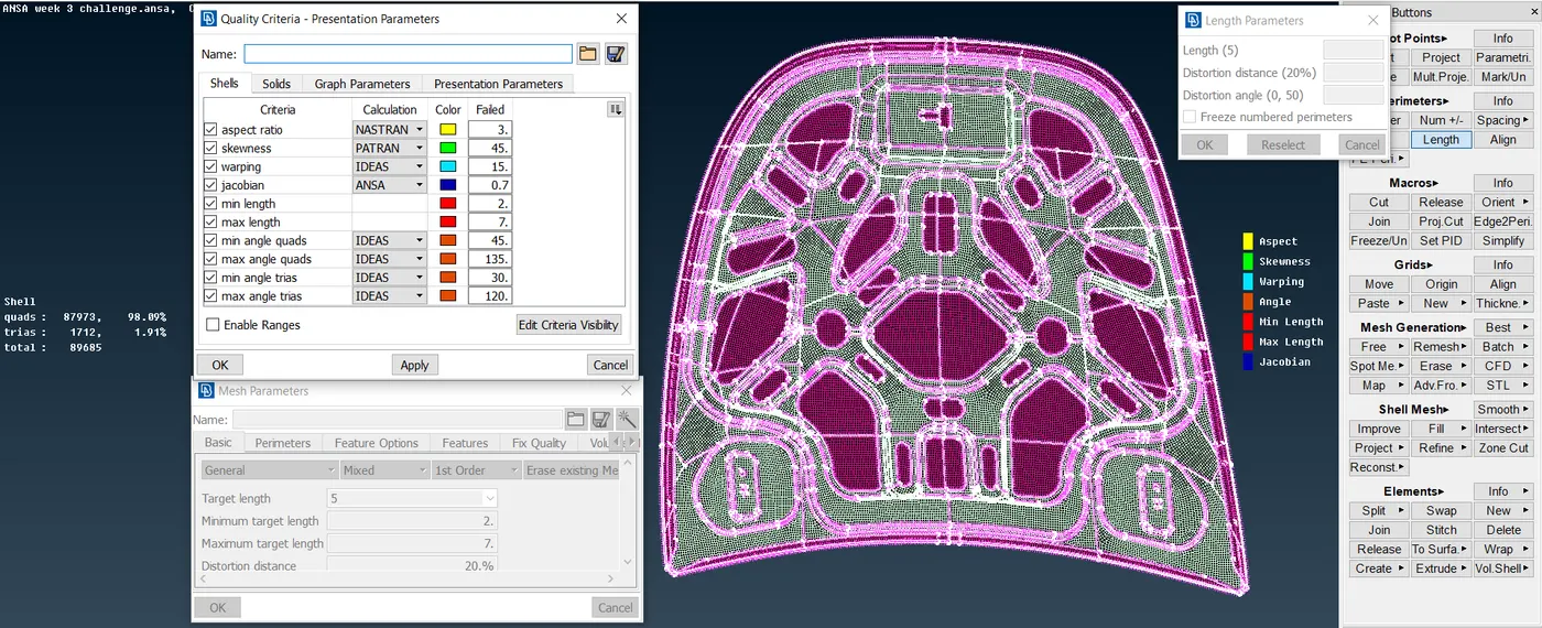
VI. Lastly, our motive for the good mesh flow is achieved. Now, we have to give thickness assignment to the solid model. Similarly, we can showcase the mesh model with selecting the 'Bounce' option and deselecting the 'Perims points' option. Like, mesh model will be appeared along with trias percentage and zero off elements.
5. Learning Outcome:-
- First, from basic we get to know basic commands and their appliactions purpose with opportunities.
- Next, we have a brief knowledge about all commands in 'Topo' and 'Mesh' mode. Specifically, we get to know how these commands should we use along with the model.
- Next, we get to know about the geometrical errors and Topology clean-up in model for the 'Topo' mode. For same, we get to know the term 'Mid-surfacing'.
- For the 'mesh' mode, we get to know how we can get a better mesh flow along with introduction of trias, quads, off elements etc.
- At last, we get a keen knowledge in the sheet-metal applications.
6. Conclusion:-
In this model, we have finally acheived a good mesh flow, along with zero 'Off' elements, by resolving all geometrical errors along with the Topology clean-up, by satisfying all quality criteria as per mentioned above, and by reducing trias percentage as below 15% as per given condition. At last, our model is mesh with a good mesh flow.