Week- 5 - Solid meshing
SOLID Meshing Of Rear View Mirror Using ANSA
Aim:-
To determine the rear view mirror component, check for the geometrical errors and mesh the Surfaces with the given 2D element quality criterias as per mentioned below-
| Sr No. | Quality Criteria | Value |
| 1 | Target/Average Length | 1 |
| 2 | Maximum Length | 2 |
| 3 | Minimum Length | 0.5 |
Additionally, use tetra elements to mesh the volumes defined in the model and check for the below quality after volume meshing as per mentioned below-
| Sr No. | Quality Criteria | Value |
| 1 | Tet Collapse | 0.2 |
Procedure:-
1. Open the ANSA Software.
2. Click on the downloaded rear view mirror component and open it.
3. As the model will appear. Use the command 'TOPO'(Faces>TOPO) and do window selection for all the model.
- After the TOPO cleanup, then we have to check the geometrical errors for further steps of Surface and Volume Meshing.
- Firstly, we have to click on the 'GEOMETRY' in the Checks Manager(Tools>Checks>Geometry), then an Auto generated template will be occured.
- Secondly, after displaying template, likewise we have to click on the 'Execute' option in the template which will dispalyed the status of error visibility.
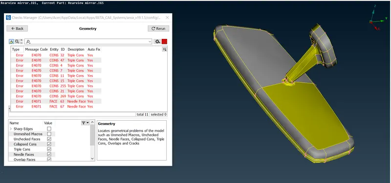
- Then, after displaying errors, we can 'Auto-fix' this error. Select all the errors and by right clicking 'Fix' option will be generated and by click on it auto-fix error will automatically be resolved one after another. For this, we have to use 'Hybrid Not'(Bullens>Hybrid Not) option.
- Admittedly, these errors should be resolves sequence by sequence, so click on error and go to the option 'show only' then the error will be displayed. Likewise, go to Release(CONS>Release) option, then by clicking on it and doing window selection of TOPO in faces, our error will be resolved respectively.
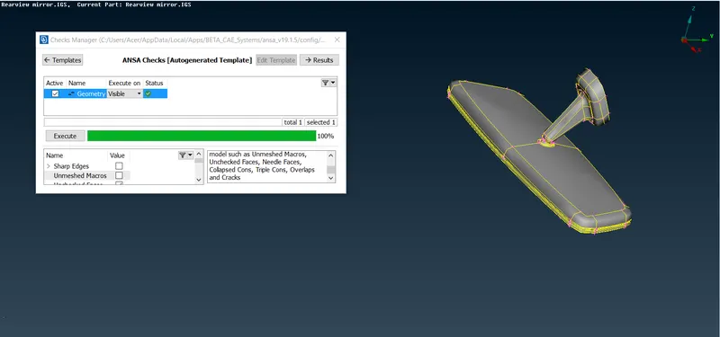
- Then, when all errors are resolved, then in template it will shown geometry check status as 100% which clarify that our geometrical errors along with TOPOLOGY clean up is up to the mark.
- Therefore, our geometry is now ready for Surface Meshing.
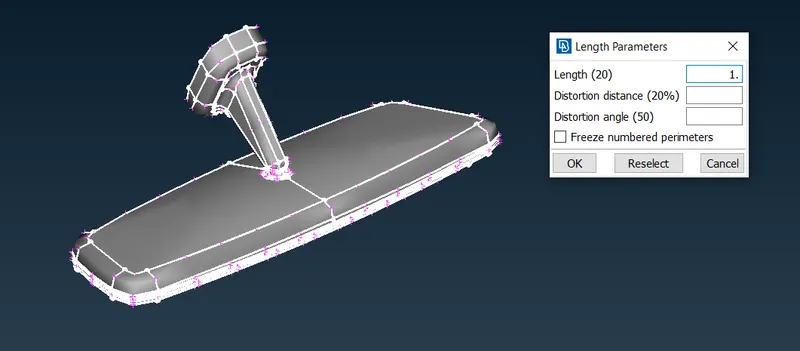
4. Basically, our model is now ready for meshing. Before that, we need to follow some protocols, likewise primarily one of its distance between nodes at perimeter and macros. We have to measure distance and like, we have to focus to attain a same distance between nodes as well as cons. Basically, we need to assign a constant distance, so need to use 'Length' (Perimeters>Length) option and we have to assign target length of '1 mm' as perimeter and macros. Then our model have a constant distance. Likewise, two protocols also we have to follow i.e. 'Number'(Perimeters>Number) and 'Slide'(Perimeters>Slide). Now, our model is ready for meshing.
5. Surface Meshing:-
Now, we have allotted 'PID' for each elements in the model. As these PID's are different, because each surface have variation in the thickness due to that we have to give unique Part ID. Accordingly, we have to set various color orientations for each element in the model. Now, different elements are mentioned below:-
- Pshell 1. (Rotating Ball)-
- Primarily, we have preferred 'Spot'(Mesh generation>Spot) mesh option for meshing. Similarly, we have to do meshing as part by part so we need to make Project cut(Macros>Project cut) to divide the surface and likewise, we have to do the mesh as part by part.
- Before that, we have to set mentioned quality criteria as per given data. So click 'F11' a template will be generated, then we have to select required quality parameters as per assigned. Then, for same we have to click 'Presentation Parameters' in the template and we have to click on the 'elements' option and we have to show the same 'Demand effect' arrow.
- After that, we have to click 'Mesh'(Utilities>Mesh) option and we have set to average, minimum and average length. Then, we have to do spot mest one after the another. Simultaneously, we have to use two commands 'Reconstruct'(Shell mesh>Reconstruct) and 'Smooth'(Shell mesh>Smooth). For reducing trias and OFF elements we have to use basically four commands namely, 'Paste'(Grids>Paste), 'Join'(Elements>Join), 'Num+/-'(Perimeters>Num +/-), 'Swap'(Elements>Swap). Thus, our element will appeared in meshing.
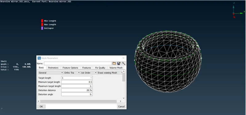
d. As, we preferred ortho tria mesh for curved surfaces and simple tria mesh for straight or normal surface. Likewise, we have to reduced OFF elements as per quality criteria for a good mesh flow.
e. Thus our objective is acheived. So, Part 1. can be viewed in 'PID' mode for its color orientation.
- Pshell 2. (Mirror)-
- Repeat the same steps of Part 1. as a,b,c.
- Likewise, our Part 2. will appeared in meshing.
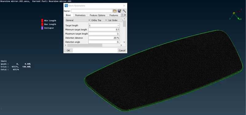
c. As, we preferred ortho tria mesh for curved surfaces and simple tria mesh for straight or normal surface. Likewise, we have to reduced OFF elements as per quality criteria for a good mesh flow.
d. Thus our objective is acheived. So, Part 2. can be viewed in 'PID' mode for its color orientation.
- Pshell 3. (Mirror Holder)-
- Repeat the same steps of Part 1. as a,b,c.
- Likewise, our Part 3. will appeared in meshing.
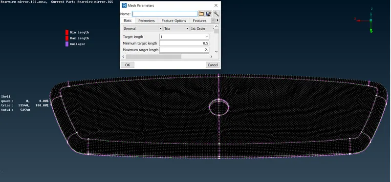
c. As, we preferred ortho tria mesh for curved surfaces and simple tria mesh for straight or normal surface. Likewise, we have to reduced OFF elements as per quality criteria for a good mesh flow.
d. Thus our objective is acheived. So, Part 3. can be viewed in 'PID' mode for its color orientation.
- Pshell 4. (Mirror Fixture)-
- Repeat the same steps of Part 1. as a,b,c.
- Likewise, our Part 4. will appeared in meshing.
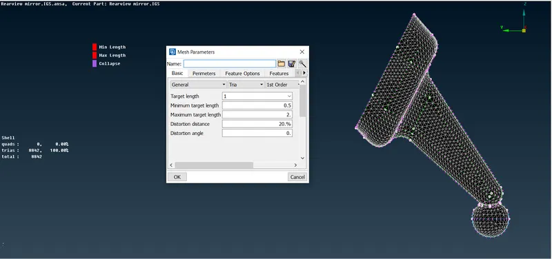
c. As, we preferred ortho tria mesh for curved surfaces and simple tria mesh for straight or normal surface. Likewise, we have to reduced OFF elements as per quality criteria for a good mesh flow.
d. Thus our objective is acheived. So, Part 4. can be viewed in 'PID' mode for its color orientation.
- Lastly, our motive for the good surface mesh flow is achieved. Similarly, we can showcase the mesh model by selecting the 'Bounce' option. For same, mesh model will be appeared along with zero trias percentage and zero off elements.
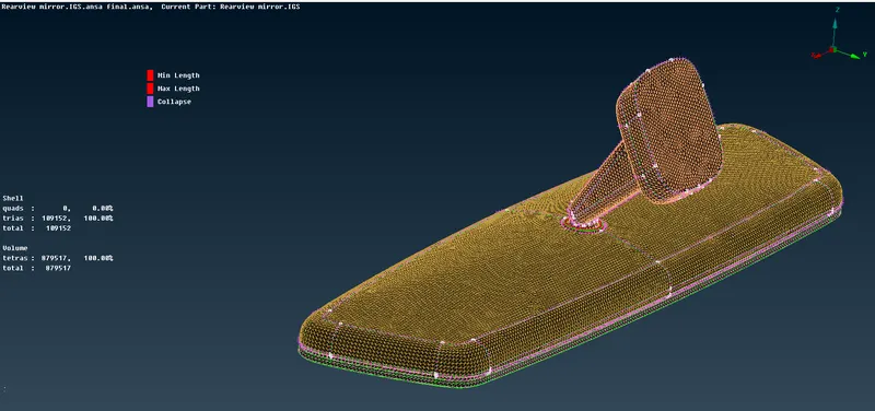
6. Volume Meshing:-
After all, we have to convert these Pshell PID's to Psolid i.e. volume mesh, of each elements in the model. Now, different solid elements are attached below:-
- Psolid 1.(Rotating ball)-
- After spot mesh has done on the surface, we need to define the volumes for each individual sepreately. This is done by using by 'Volume Mesh'(Volume>Define Volume>Manual) of the module.
- Then, after defining seperate volumes for each property in the model, PID is set for Psolid 1. (Rotating Ball) by using 'Set PID'(Volume>New>Psolid) option. After attaining, PID for Psolid 1, we do solid meshing for defined volume using 'Tetra FEM'(unstructured Mesh>Tetra FEM) option. We prefered Tetra FEM instead of Tetra Rapid because it is more organised than Rapid mesh.
- After solid meshing, we need to check the 'Tet Collapse' named quality criteria for the solid mesh flow in Property checks manager(Quality criteria>Solids), in which it should be achieved with a value of 0.2.
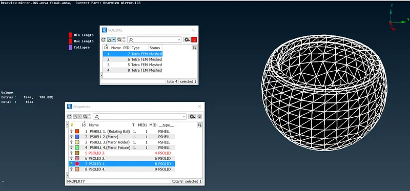
d. Thus our objective is acheived. So, Psolid 1. can be viewed in 'PID' mode for its color orientation.
- Psolid 2. (Mirror)-
- Repeat the same steps of Psolid 1. as a,b,c. for Psolid 2.
- Likewise, our Psolid 2. will appeared in meshing.
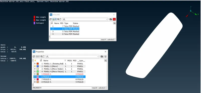
c. Thus our objective is acheived. So, Psolid 2. can be viewed in 'PID' mode for its color orientation.
- Psolid 3. (Mirror Holder)-
- Repeat the same steps of Psolid 1. as a,b,c. for Psolid 3.
- Likewise, our Psolid 3. will appeared in meshing.
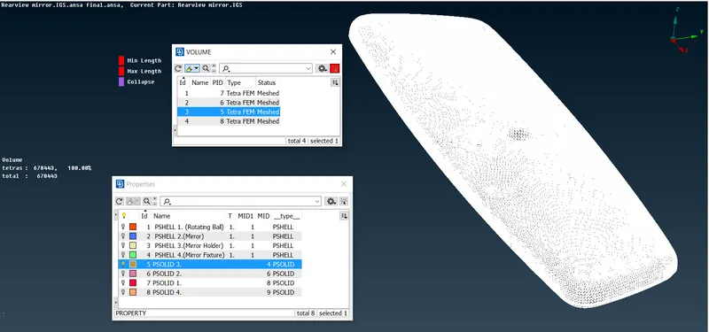
c. Thus our objective is acheived. So, Psolid 3. can be viewed in 'PID' mode for its color orientation.
- Psolid 4. (Mirror Fixture)-
- Repeat the same steps of Psolid 1. as a,b,c. for Psolid 4.
- Likewise, our Psolid 4. will appeared in meshing.
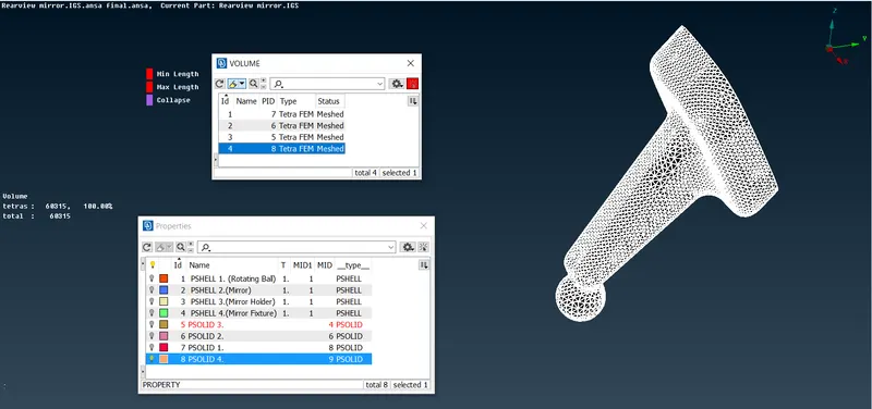
c. Thus our objective is acheived. So, Psolid 4. can be viewed in 'PID' mode for its color orientation.
- Lastly, our motive for the good volume mesh flow is achieved. Similarly, we can showcase the mesh model by selecting the 'Bounce' option. For same, mesh model will be appeared along with zero trias percentage and zero off elements.
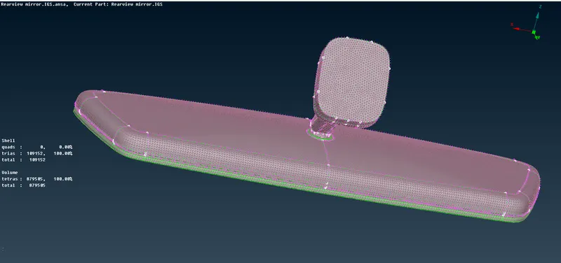
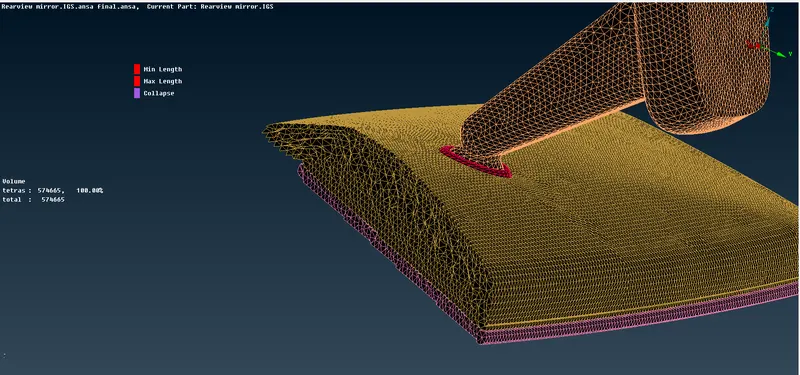
Section View- Volume Mesh
Learning Outcomes:-
- Learnt the difference between mesh flow with tria and ortho tria.
- Learnt the volume mesh flow.
- Learnt the difference between Unstructured mesh with Tetra Rapid and Tetra FEM.
- Learnt how to fix the Penetration or Intersection errors.
- Learnt how to fix quality criteria as per requirement.
Conclusion:-
In this model, we have finally acheived a good surface and volume mesh flow, along with zero OFF elements, by resolving all geometrical errors along with Topology cleanup and by satisfying given quality criteria for shell and solid both as per mentioned requirement. Atlast, our model has attained a better mesh flow.