Week 5 Sphere pressing on a plate
Simulation of Sphere pressing over the Flat Plate:
Aim: Simulation of Sphere pressing over the flat plate with Structural Steel NL material for both & maximum displacement of the sphere along negative Y axis of 4mm, in order to calculate maximum directional plastic deformation.
Introduction: In order to make a component suitable for various purposes during manufacturing-Metal Forming process takes place were various components are deformed upto plastic region with the help of various tools applying different kinds of displacement & loads on dies & tools to change its shape & size permanently.This plastic deformation can take place at room temprature or at high & low tempratures depending on the user defined requirements of parts to be manufactured.
Cold Working:Deformation at room tempratures is known as cold working, which increases Strength but at the same time decreases ductility and also increases anisotropy due to which,each material property becomes dependent on directions.Cold Working also known as Strain hardening, can be used for both metals & alloys.
Steps followed:
1) Material selection:
Structural steel is selected for both sphere & plate for simulation, with material properties listed below: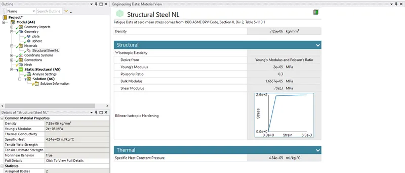
2)Geometry:
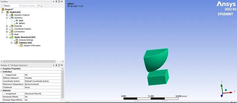
Sphere & flat plate with 1/4 part is taken for simulation, as we have to make analysis time less during simulation but with results close to that of entire body system.
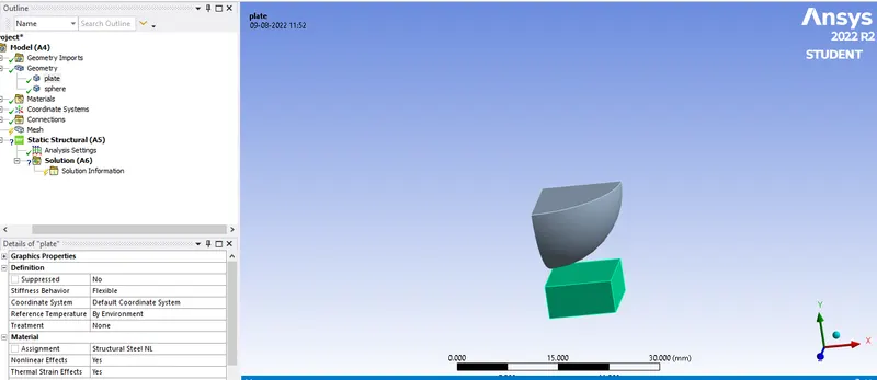
After renaming both the parts as Sphere & Plate. Both the Sphere & plate is selected to assign Structural Steel NL material to them.
3)Symmetry:
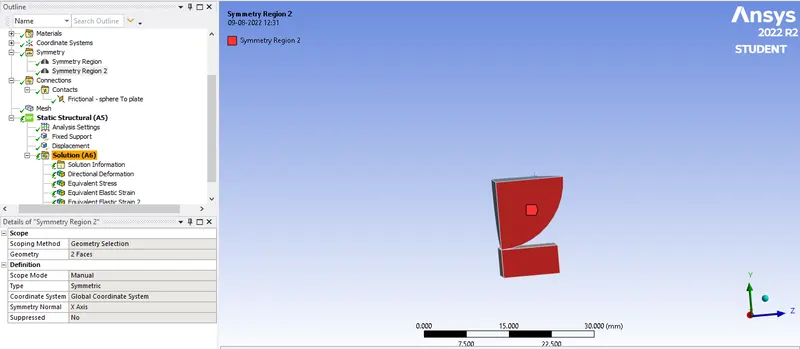
Each one face of sphere & plate is selected for symmetry twice with Symmetry Normal to be Z & X axis respectively.
Symmetry Region along Z axis:
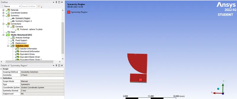
Symmetry Region 2 along X axis:
4)Contacts:
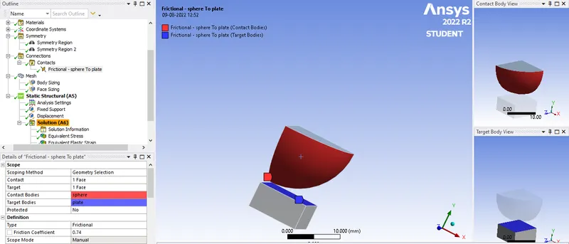
From Connections go to Contacts, delete all the intial contacts and with righ click of mouse-Insert-Manual contact region. After this,select curve face of sphere as Contact and Target is selected for plate with face that comes into contact with curve surface of sphere, with Frictional Type contact and frictional coefficient as 0.74 from roymech tribology table for Steels(Mild):
5)Meshing:
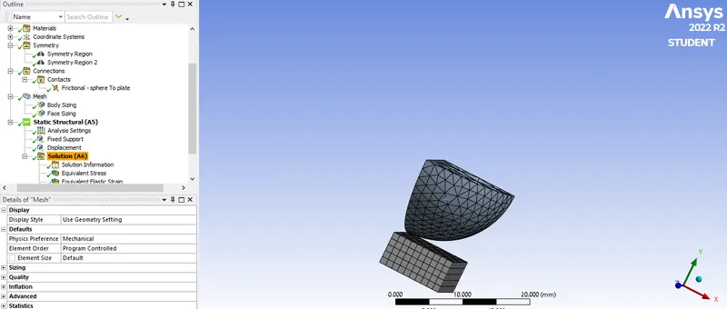
With right click we have inserted Body sizing of 1mm to the plate and Face sizing of 1.5 mm to the curve surface of sphere.
6)Boundary Canditions:
- Analysis Settings:
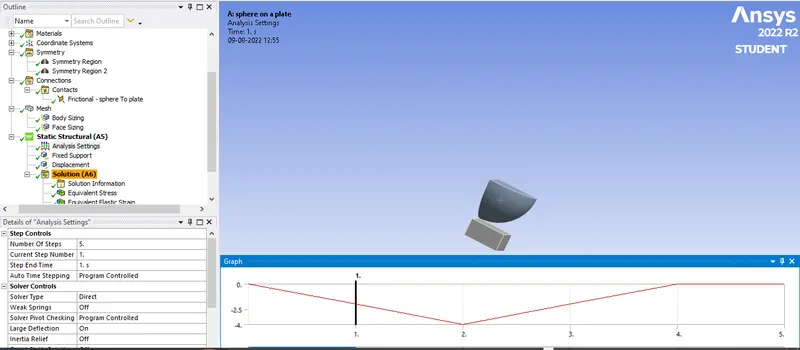
In analysis settings Number of Steps is considered as 5 with Solver Type as Direct and Large Deflections is switched On.
- Fixed Support:
Fixed support is applied by selecting the downward face of the Plate.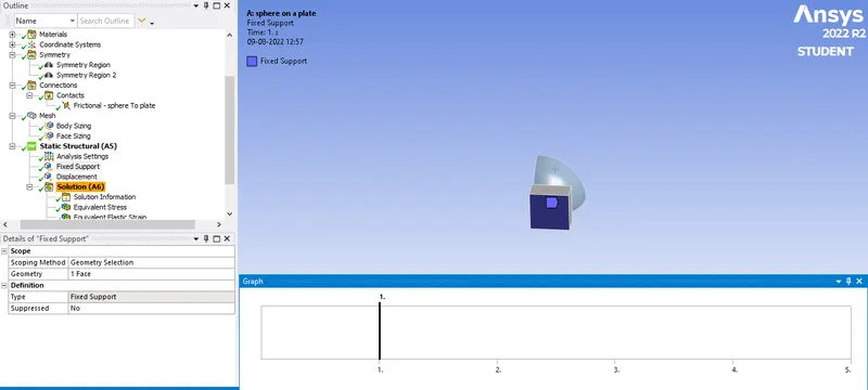
- Displacement:
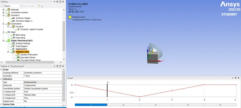
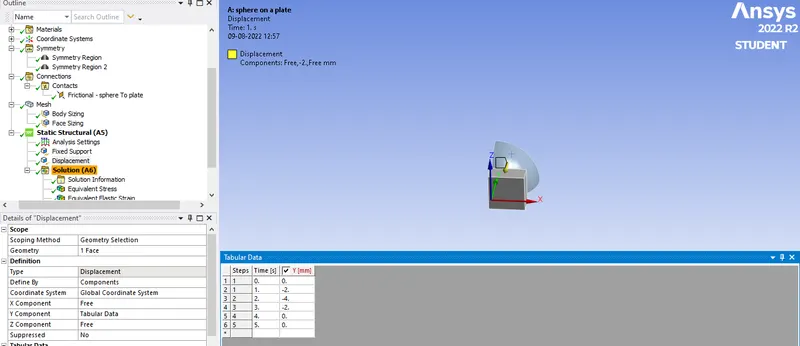
Displacement is applied by selecting the upper face of sphere in Tabular format along negative Y axis with its maximum value of 4mm in 5 steps.
Results:
1)Directional Deformation of whole setup:
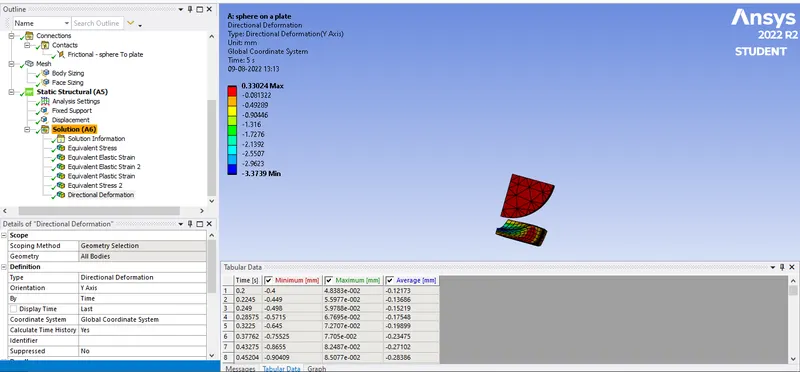
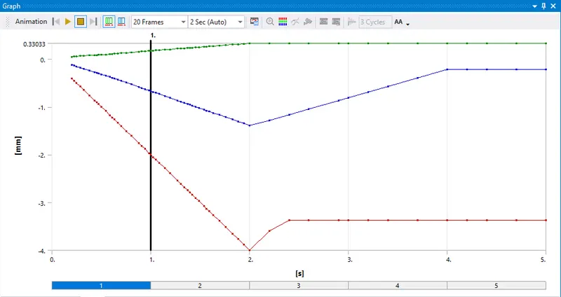
Directional Plastic deformation along negative Y axis can be seen as displacements are applied in that particular direction to the sphere.
Deformation Graph:
2) Equivalent Stress for the whole setup:
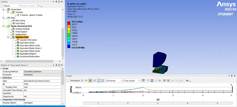
Maximum Equivalent Stress for the whole setup:3237.4 MPa.
Equivalent Stress vs Time Graph: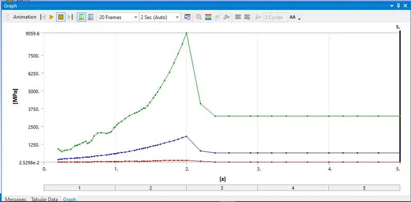
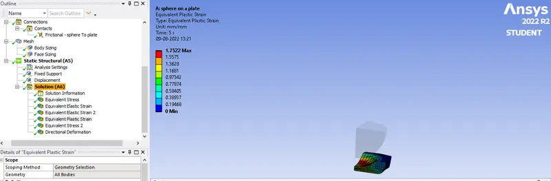
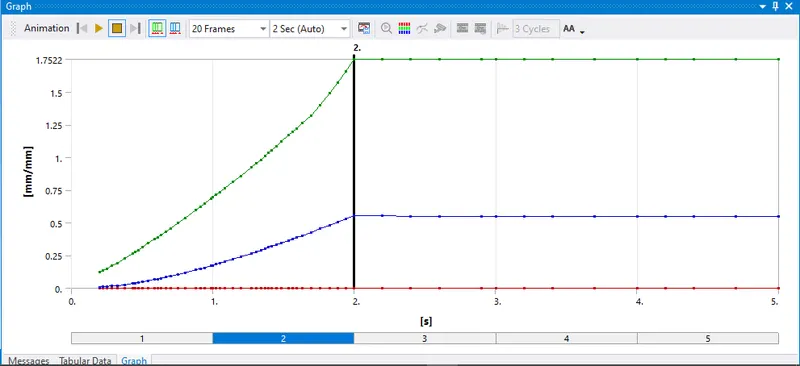
Equivalent Plastic Strain for the plate:
Conclusion:
- The maximum displacement of 4mm occurs at the step 2 after which sphere is returned back.
- Maximum Directional Deformation occurs downward along negative Y axis is 3.739 is Plastic deformation because after returning of sphere from the plate contact, plate does not returns to its original shape.
- Maximum Equivalent Plastic strain is 1.7522which is steady from step 2 to step 5.
- Plastic Deformation in Forming-manufacturing process is of greater significance compared to the elastic one, as we can get the desired shape without any chances of components to return back to its original shape & size.