Week 5 Sphere pressing on a plate
Aim: To perform a simulation for a sphere pressing a flat plate.
Model Setup:
A CAD model for a quarter sphere has been imported into Ansys static structural workbench.
Non-linear structural steel was added to the material library. It was assigned to the plate of the model. The sphere was general structural steel.
Contacts were defined for the model sphere as contact body and the plate as target body as shown in image 1. The type of contact was frictional with a friction coefficient of 0.74 taken from Roymech useful tribology tables.
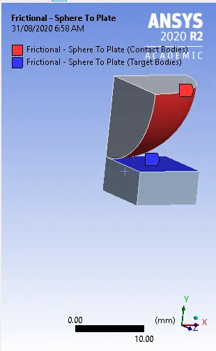
Image 1:Contact definition
Symmetry was defined for the sphere and plate in x and z- directions.
Mesh size of 0.8mm was given resulting in 10152 nodes and 3516 elements as shown in image 2.
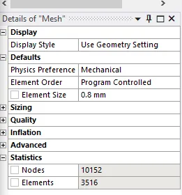
Image 2: Mesh details.
Analysis settings:
The analysis was set up for 4 steps and solver type was direct with large deflections ON as shown in image 3.
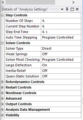
image 3: Analysis settings.
The bottom end of the plate was fixed as shown in image 4.
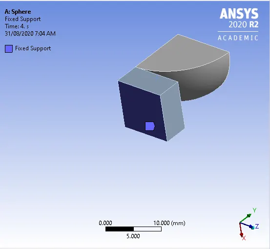
The displacement was defined in the negative y-direction as shown in table 1 and defined on the top of the sphere surface as shown in image 5.
| Time | Y(mm) |
| 0 | 0 |
| 1 | -3 |
| 2 | -4 |
| 3 | -2 |
| 4 | 0 |
Table 1: Displacement loading
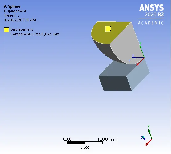
image 5: displacement definition
Results and Conclusions:
The directional deformation in the y-direction is shown in image 6.
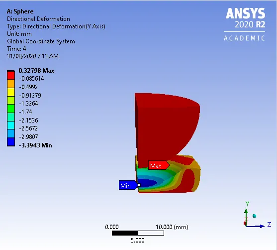
Image 6: Directional Deformation.
The equivalent stress developed in the plate is shown in image 7.
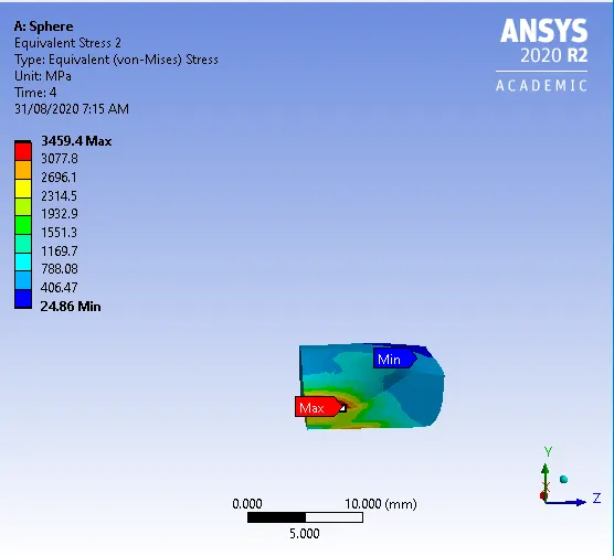
image 7: equivalent stress on the plate
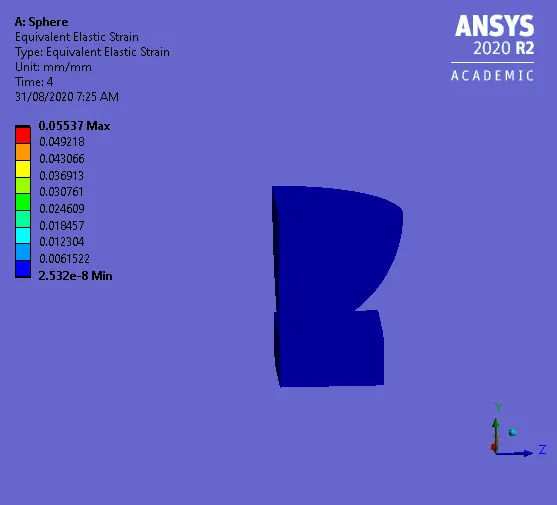
The equivalent strain developed in the whole model is shown in image 8
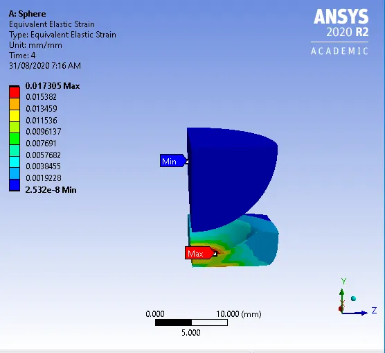
Image 8: equivalent strain
The plastic strain developed in the plate is shown in image 9
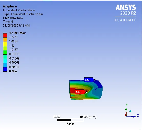
Image 9: Equivalent plastic strain
From the above results, we can conclude that the stresses and strain are maximum in the plate at the maximum contact region. It can be seen that the plate does not retract to its original shape after deformation since it reaches the plastic region as shown in the video below.