Week- 5 - Solid meshing
AIM:
- Check for the geometrical errors and mesh the Surfaces with the given 2D element Quality criteria’s given below for given REAR VIEW MIRROR.
- Use tetra elements to mesh the Volumes defined in the model and check for the below quality after Volume meshing.
|
SI. No. |
Quality Criteria |
Value |
|
1 |
Target/Average length |
1 |
|
2 |
Minimum Length |
0.5 |
|
3 |
Maximum Length |
2 |
|
SI. No. |
Quality Criteria |
Value |
|
1 |
Tet collapse |
0.2 |
Note:
- For 2D Elements, Only check for Min length and Max length errors.
- For 3D Elements, Only check Tet Collapse errors.
PROCEDURES:
In TOPO Module
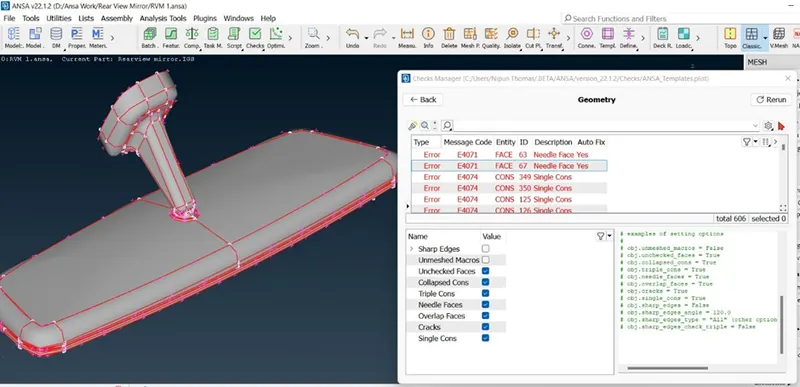
- Geometry check
- Check for Geometry errors from Tool Menu Bar.
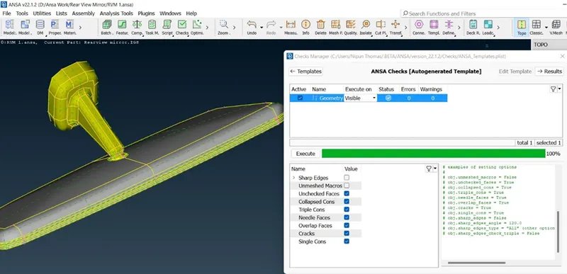
- Execute the operation and wait for the results.
- If Errors are generated then select all the Errors. Right click the mouse button to auto fix the errors.
- If not cleared, fix manually by releasing the cons and applying TOPO from TOPO Module.
- Orient the model using Orient tool from Faces Options.
2) Lock the VIEWS.
- Lock the views by selecting each component separately for meshing the parts individually.
In CLASSICAL MESH MODULE
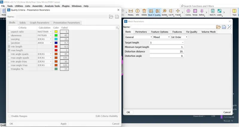
- Assign Parameters by accessing Quality criteria and Mesh Parameters from TOP toolbar as per given values in the question.
- Assign Target Length (1 MM).
[Since some regions might fail for minimum tool, they can be modified by taking care of the boundaries (cons). The cut tool can be used to suppress some of these cons and in other regions, we can create cuts. All this to ensure the mesh generated would be favourable and does not fail for any of the criteria.] This method is also called DEFEATURING.
MESH GENERATION
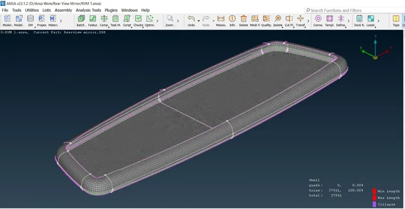
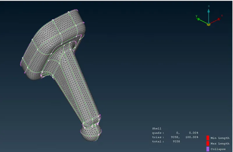
- To mesh the component, we can use SPOT MESH.
- TRIA MESH can be used for plane or flat surface areas.
- ORTHO TRIA can be used for curved and other complicated parts (Fillets and Hemmings).
After deploying Mesh, it is advised to reconstruct the mesh to ensure there are no OFF ELEMENTS by using RECONSTRUCTION tool in SHELL MESH.
In VOLUME MESH MODULE
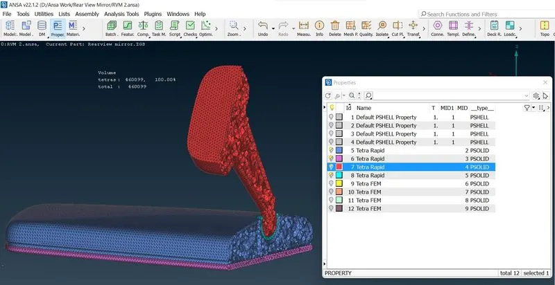
Assign volume manually to each set of closed components by using MANUAL Option in DEFINE.
We can see that PROPERTY ID has been set automatically, and individual parts can be selected from PID tool bar.
After selection, Middle click the mouse button for ANSA to recognise the volume.
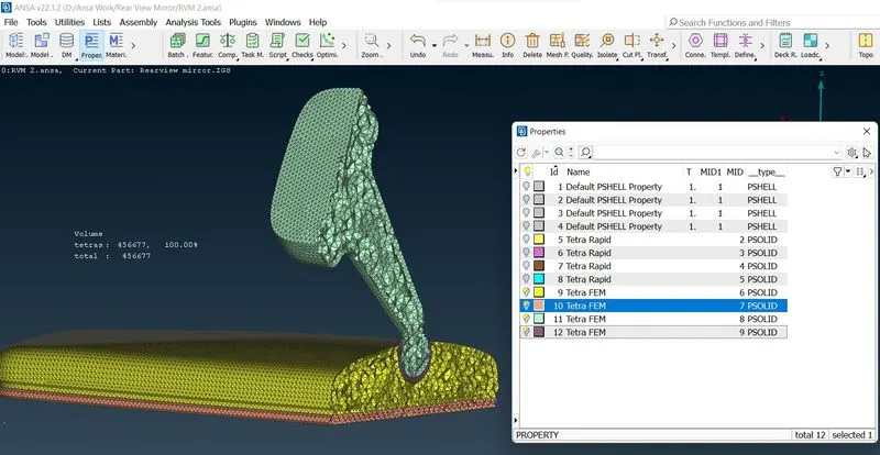
Once the volume is identified, select them individually and edit the type of Volume Mesh that needs to be deployed (TETRA RAPID, TERTA FEM, TETRA CFD, …).
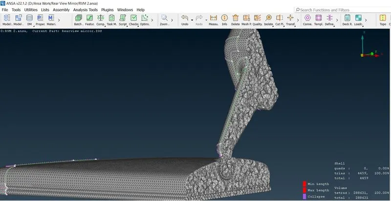
Right click each VOLUME and select REMESH and check if any elements collapse for COLLAPSE CRITERIA by switching it to hidden mode.
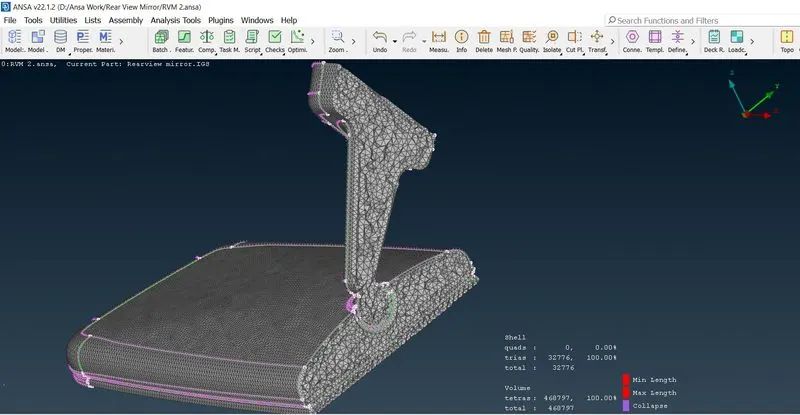
TO FIX COLLAPSED ELEMENTS
Using FIX Quality tool from VOLUME MESH MODULE. (This may result in producing dents or kinks on the surface).
Using MV FREE tool in GRIDS. (This lets us manually alter the height by moving the nodes in particular way by choosing proper Co-Ordinates).
(I had set the Collapse rate of 0.3 to get more accurate volume after I got 0 OFF ELEMENTS at 0.2 Collapse rate).
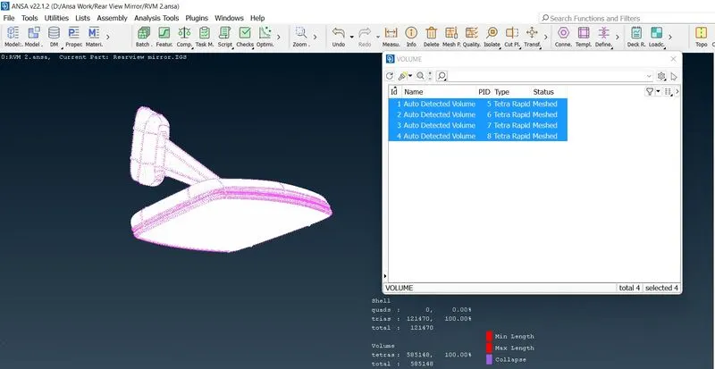
LEARNING OUTCOMES:
- To use some of the tools related to solid meshing.
- To assign volumes for closed shell element regions.
- To fix tet collapse failures using Manual as well as Auto Fix Method.
- Where to deploy ortho tria and tria mesh types through the spot mesh tool.
CONCLUSION:
The given component was geometrically fixed and meshed as per the given quality criteria.
Generated shell mesh was used to create the solid mesh.
Quality and flow were achieved
Ensured that there were no deformations of any kind on the surface.