Week 2 Bevel Gear Challenge
OBJECTIVE: The objective of this project is to perform a grid dependency test for bevel gear with different mesh sizes, i.e., 6, 5, and 4 mm. Evaluate and Compare their von-mises stress, equivalent elastic strain, and total deformation.
Different Cases For Analysis are as given below
CASE 1: Mesh size 6mm
CASE 2: Mesh Size 5mm
CASE 3: Mesh Size 4mm
GRID DEPENDENCY TEST:
The grid dependency test, where analysis begins with a coarse mesh, is refined to finer mesh for each run until the results do not change significantly and depend on the grid size anymore. As the grid or mesh size approaches zero, the approximate solution is almost equal to the actual solution.
In other words, The Grid dependency test investigates how the solution depends on the grid size by running the simulation with refined mesh that is finer the mesh. Higher is the accuracy of the result but with additional cost on computation time and computational power. Since solutions are interpolated at the nodes to get an approximate result, the higher the number of nodes and elements higher is the computational time and power required to complete the simulation.
So, the grid dependency test helps in determining optimal mesh size where the accurate result could be obtained keeping in the mind the cost of time and power. Since the result obtained are approximate,
Refining mesh further would result in negligible percent change in the result but only increase the computational cost.
STEPS FOR PERFORMING ANALYSIS:
1. Open ANSYS workbench.
2. Select the static structural module.
3. Select the proper Engineering data card.
4. Import geometry.
5. Open Mechanical model.
6. Give proper connections (contacts and joints).
7. Generate mesh.
8. Set Analysis Setting as per given.
9. Insert output request
10. Analyze Result.
ANALYSIS SETUP:
GEOMETRY
Import given model in ANSYS Workbench for static structural analysis. The Bevel gear has 24 & 16 teeth with driver gear being named as right gear and driven gear being named as left gear respectively.
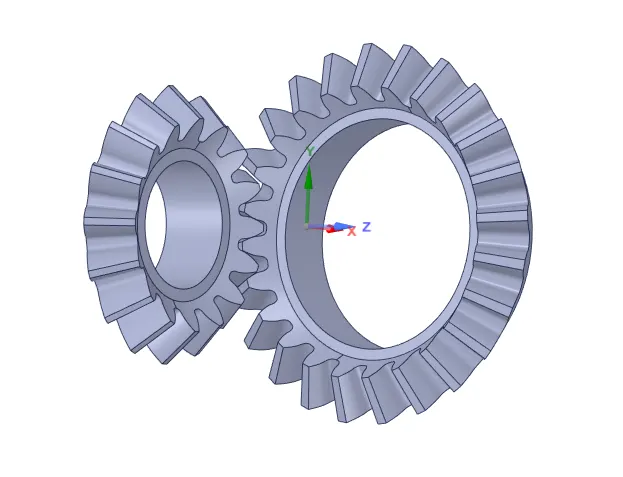
Fig.1 Bevel Gear CAD model
MATERIAL PROPERTIES:
Material is same for all the cases.
- Structural steel
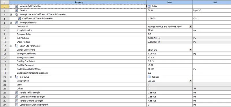
Fig. 2 Material Property
PROCEDURE FOR ALL CASE:
1. Import model in ANSYS Workbench.
2. Assign material properties.
3. Open the mechanical module where we going to perform analysis.
4. Rename Both the gear as Small and Big.
5. Meshed the model with desired element size.
6. Now after meshing, From Project Tree, select "Connections" and create "Contact".
- CONTACTS:
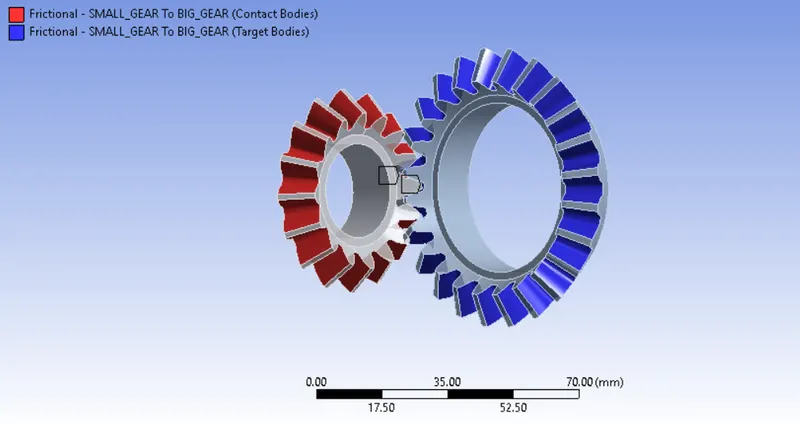
Fig. Contact between Gear
- For defining contacts between two spur gear, select faces of Big gear as "TARGET" and select faces of Small gear as "CONTACT". There are 16 and 24 faces on Small and Big gear respectively, must be selected.
- Select Contact type as "Frictional" Contact, due to friction there will be movement between gears.
- Select Behaviour as "Symmetric". In the symmetric type of behavior, both the contacting surfaces are taken as
contact and target. - Select Formulation as "Augmented Lagrange". As soon as teeth come in contact, they will tend to move from their position, So Augmented Lagrange formulation reduces vibration, penetration and The contact force becomes less sensitive to the stiffness.
- Select Interface Treatment as Adjust to Touch, Because if there is a gap between them or initial penetration, this setting will help adjust it, and error can be avoided.
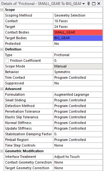
Fig. Defining Contacts between gears
7. JOINTS:
After the creation of Contact between gears now create joints.
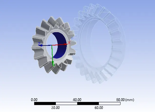
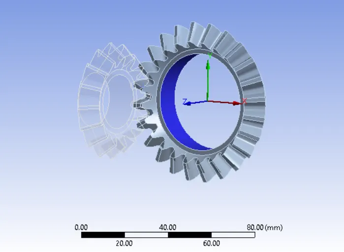
Fig. Left Gear Fig. Right Gear
- Select the inner face of both gear and give it a revolute joint as shown in the above figure.
- Select Connection Type as Body to Ground for both the gears.
- Here We can see in revolute workbench automatically select the axis of rotation for both gears is the z-axis.
BOUNDARY CONDITIONS:
Now let's define the Boundary condition.
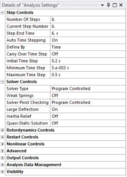
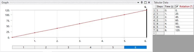
- Here we are going to look at contact faces and stress developed for 1 revolution of Bevel Gear. So for 120-degree angle, In the Analysis setting as shown in the figure.
- Select all the steps Before defining step tine and select "Large Deflection = ON" in solver controls.
- Other boundary Conditions for joints are given below
Joint Load:
- Joint: Revolute-Ground to Small_Gear
- Type: Rotation
- Magnitude: Tabular Data
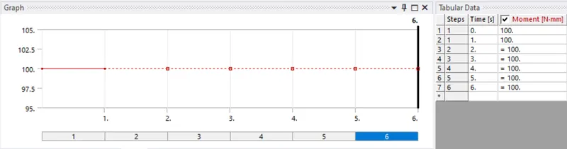
Tabular Data:
- Joint: Revolute-Ground to Big_Gear
- Type: Moment
- Magnitude: Tabular Data
Tabular Data:
9. SOLUTION:
- After giving proper Boundary conditions, create a solution for output results.
- Create Solutions for Equivalent von-mises stress, Equivalent elastic strain, and Total deformation.
RESULT:
Result and discussion For all cases.
CASE 1: Mesh Size 6mm
1. Meshed Model:
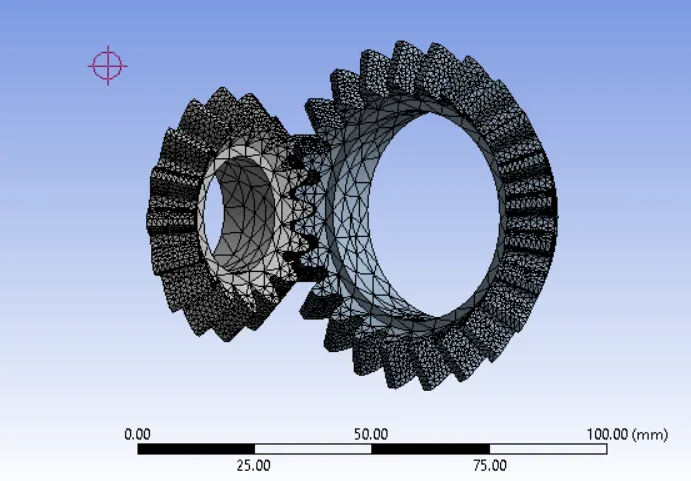
Fig. Meshed Model (6mm)
Details:
- Global Element Size = 6mm
2.Face Element Size = 1.25mm
3.No. of Nodes = 44773
4.Element = 24703
2. Equivalent von-misses stress:
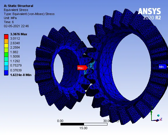
Maximun Stress = 3.3876 MPa
- Stress Plot and Detailed stress values:
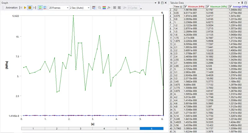
Fig. Stress plot and stress values w.r.t Time.
3. Equivalent Elastic Strain:
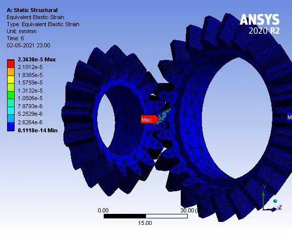
Maximum Strain = 2.3638e-5 mm/mm
- Strain Plot and Detailed Values:
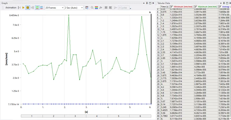
Fig. Strain Plot and Strain Values w.r.t. Time
4. Total Deformation:
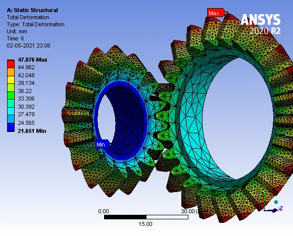
Maximum Deformation = 47.876 mm
- Deformation Plot and Detailed Deformation values:
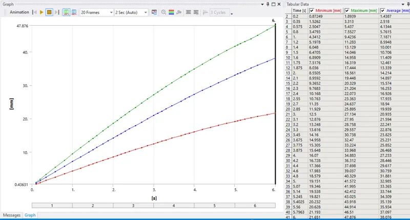
Fig. Deformation Plot and values w.r.t. Time
CASE 2: Mesh Size 5mm
1. Meshed Model:
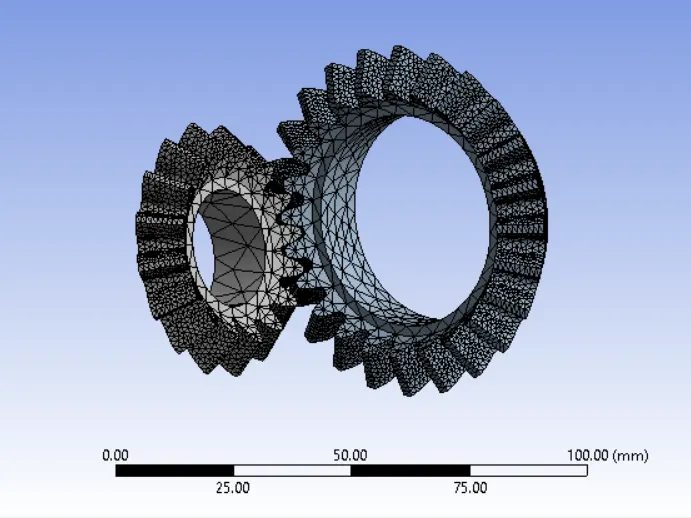
Fig. Meshed Model (5mm)
Details:
- Global Element Size = 5mm
2. Face Element Size = 1.25mm
3. No. of Nodes = 45210
4. Element = 24938
2. Equivalent von-misses Stress:
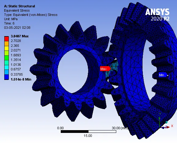
Maximum Stress = 3.0407 MPa
- Stress Plot and Detailed Values
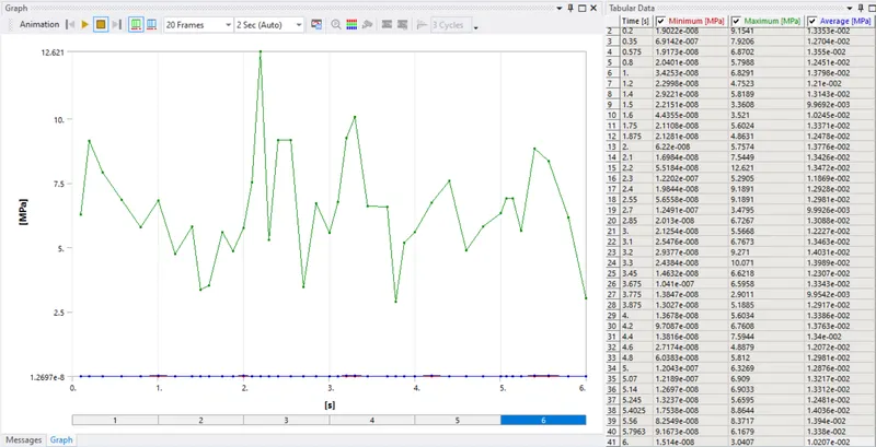
Fig. Stress Plot and Stress values w.r.t. Time
3. Equivalent Elastic Strain:
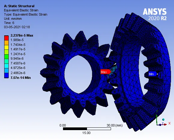
Maximum Strain = 2.2376e-5 mm/mm
- Stress Plot and Detailed values:
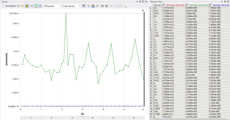
Fig. Strain Plot and values w.r.t. Time
4. Total Deformation:
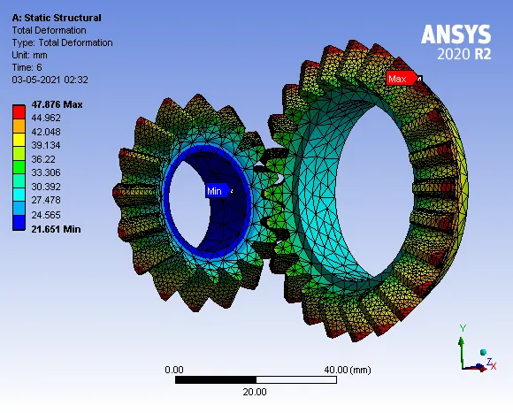
Maximum Deformation = 47.876 mm
- Deformation Plot and Detailed Values
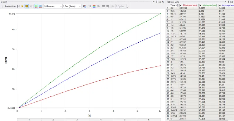
Fig. Deformation Plot and Values w.r.t Time
CASE 3. Mesh Size 4mm
1. Meshed Model
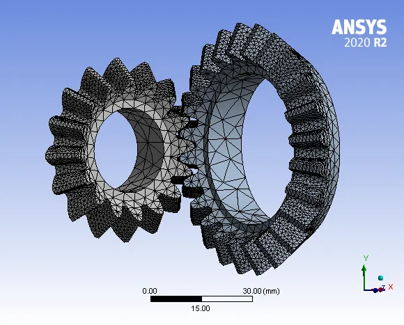
Fig. Meshed Model (4mm)
Details:
- Global Element Size = 4mm
2. Face Element Size = 1.25mm
3. No. of Nodes = 45192
4. Element = 24871
2. Equivalent von-misses Stress:
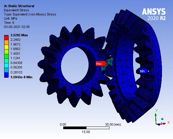
Maximum Stress = 2.5292 MPa
- Stress Plot and Detailed Values:
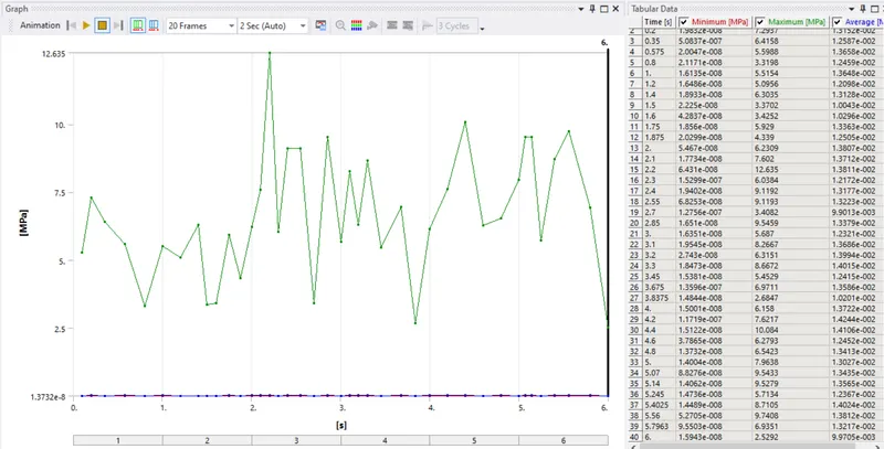
Fig. Stress Plot and Values w.r.t. Time
3. Equivalent Elastic Strain:
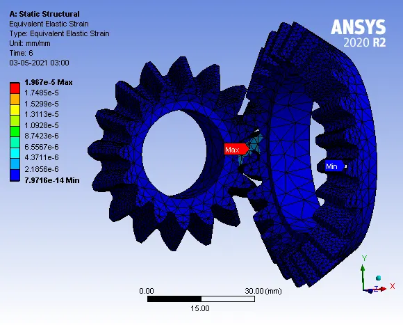
Maximum Strain = 1.967e-5 mm/mm
- Strain Plot and Detailed Values:
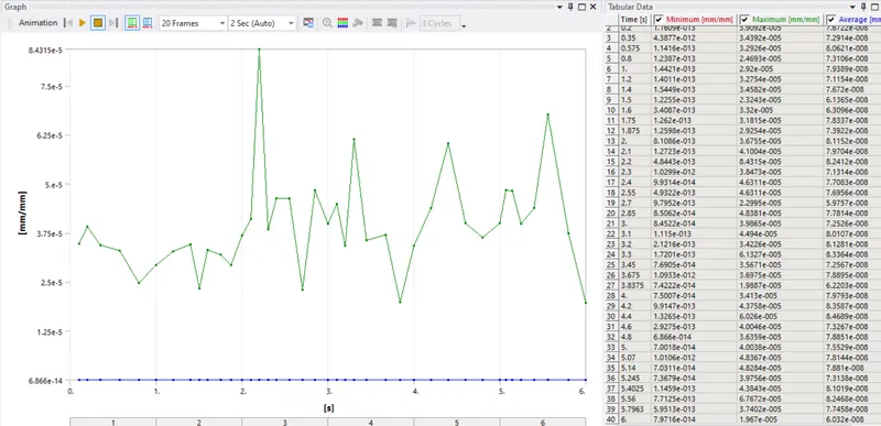
Fig. Strain Plot and Values w.r.t. Time
4. Total Deformation:
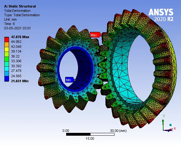
Maximum Deformation = 47.876 mm
- Deformation Plot and Detailed values:
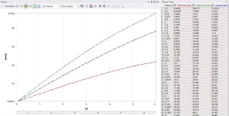
Fig. Deformation Plot and Values w.r.t. Time
Comparison:
| CASE | Max. Total Deformation (mm) |
Max. Equivalent Stress (von-misses) (MPa) |
Max. Equivalent Elastic strain (mm/mm) |
|
CASE_1 Mesh Size 6mm |
47.876 mm | 3.3876 MPa | 2.3638e-5 mm/mm |
|
CASE_2 Mesh Size 5mm |
47.876 mm | 3.0407 MPa | 2.2376e-5 mm/mm |
|
CASE_3 Mesh Size 4mm |
47.876 mm | 2.592 MPa | 1.967e-5 mm/mm |
CONCLUSION:
Grid Dependency test has been performed and From the above table, we can conclude performing grid dependency test on bevel gear by varying the global size of the mesh we achieve much better accuracy of the result. We can observe that as the mesh is refined from e.g 5mm to 4mm we achieve better approximate of the result for equivalent elastic strain and equivalent stress, however, performing the simulation with further refining the mesh would result in a very close approximation of the result but with very negligible change in the result with an additional on the computational power and time.