Week 5:- Rest Unit & Clamp Unit Design Challenge
Design of Rest Unit & Clamp Unit
Objective: To understand and design 2 different types of Rest Units for the given Car Panel.
OBJECTIVE:
- To Design 3 Different types of Power Clamp Unit with Different Riser, Blade and Clamp Arm for the given Car Panel.
- To Design 2 Different types of Rest Unit for the given Car Panel.
INTRODUCTION:
Clamp unit is used to hold the car panel or component in fixture woth the help of mylars or NC blocks using manial pneumatic clamp cylinder. This unit only restricts up and down motion of car panel.
Various parts used:
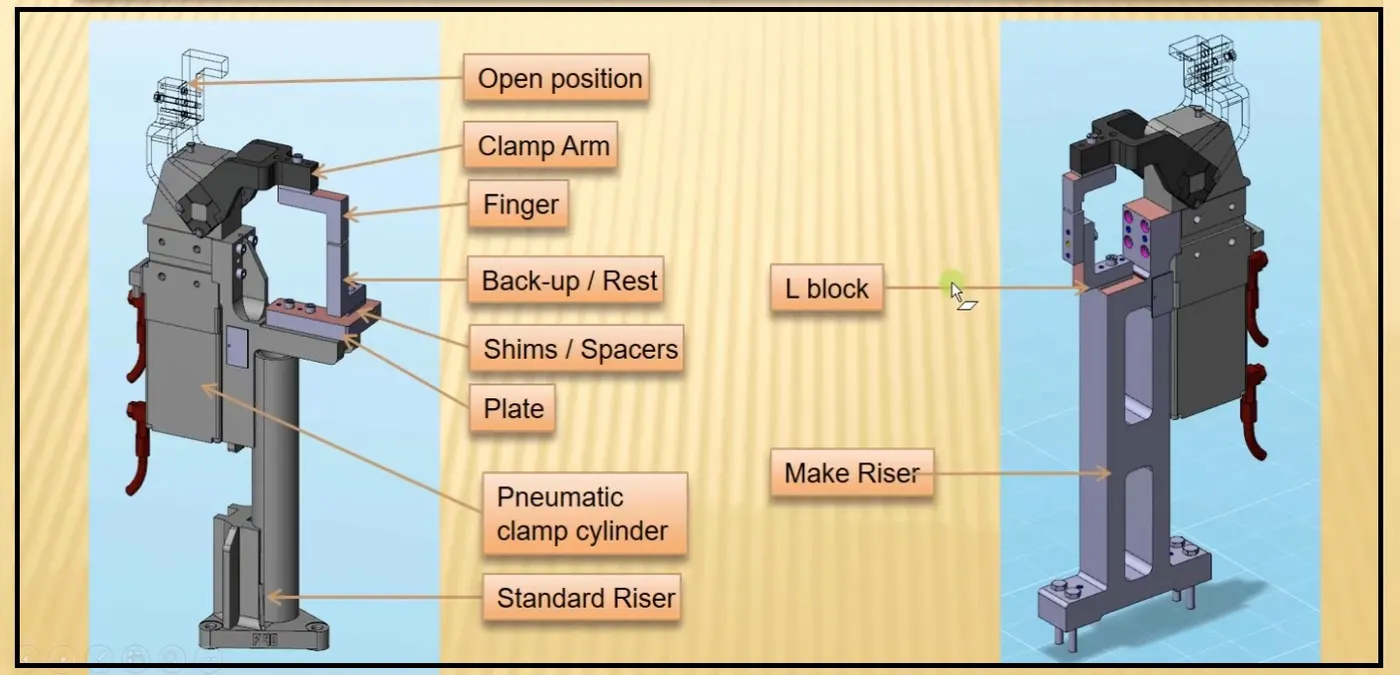
Clamp Mylars - This part is in actual contact with the car panel as it hold or clamp the component.
Rest mylar - This part also is in acrual contact with the car panel as car panel rest on this part.
Blocks - Block can be machined in any desired shape according to fixture. It is normal shape of rectange or square clock or L type shaped block.
Shims or spacer - shims or spacer are used to compensate tolerance stack up. In pin unit we need to control two direction that are C and Y using shims or space. Shims are generally thin sized plates used in group called shimpack and spacer are used as single plate and can be mcahined accordingly.
Blade- blades are bolted on riser
Riser - Riser are used to increase the height of the fixture and it is a standard parts.
To understand and design 3 different types of Power Clamp Unit with different Riser, Blade and Clamp Arm for the given Car Panel.
Introduction:
Rest Unit: Rest unit is a unit designed to support a car panel using Mylar/ NC block/ rest component is rested only, no upper clamp or force applied there. It is the simplest unit to design because it has fewer parts to design & the purpose is only resting of the car panel.
Because of the simplicity, the rest unit is combined with another unit to reduce the cost of the overall project.
It can be combined with a clamp unit to clamp as well as to rest the car panel. It can be combined with locating unit to locate as well as to rest the car panel. Also locating, clamping & Test unit can be combined together in one unit to reduce cost.
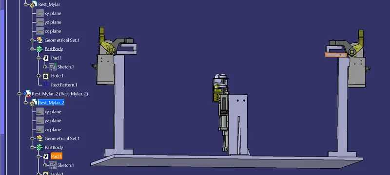
There is no cylinder attached to it. It has rest Mylar, blade, and riser & below is different parts of the rest unit. Rest unit is also divided into simple support unit, multiple support units & retractable support units.
Clamp Unit: A clamp unit is a unit designed to clamp/hold the car panel with NC blocks/Mylars/rest by using a pneumatic cylinder. Clamp arm, finger, Rest/backup, Lblock, shims, riser, pneumatic cylinders are the typical parts of clamp unit.
Clamping force should be considered while designing a clamp unit. Usually clamp open position is 90. Fingers are attached to clamp Mylar.
In the Clamp unit shim to one side is more enough because it will restrict translation motion in an upward direction and downward direction only.
There is another type of clamp unit known as the swivel type. There is a pivot pin around which the clamp arm rotates.
Purpose of Rest Unit &Clamp Unit:
- The purpose of clamping tools is to securely hold the workpiece in position without obstructing the production process.
- It prevents distortion during the welding process and other processes.
- High clamping forces combined with compact dimensions are therefore the most important requirements for a clamping
tool. For this reason, clamps are also equipped with mechanical transmission gear units.
Design Methodology:
- 3-2-1 Principle achieved by clamping and resting: The 3-2-1 principle is the fundamental principle of all fixture design. While designing a fixture a major part of time is spent in locating the workpiece in the fixture.
- The best & the most effective method of part location is referred to as the 3-2-1 method. Fixtures work on the 3-2-1 principle.
3 locators or supports are placed under the workpiece which establishes the part plane. Three locators are generally positioned at the primary locating surface. - This restricts 2 axial movements downward & upward and 4 radial movements. As a result the 3 locators arrest six degrees
of freedom.
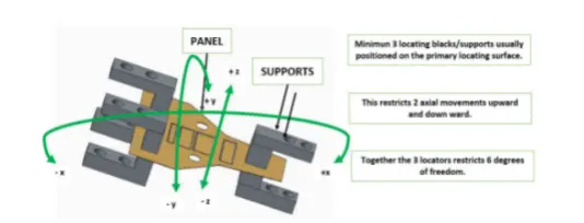
- Thus by using the 3-2-1 principle, introducing a minimum of 3 clamping & resting blocks will restrict 6 DOF( 2 axial translational about z-axis & 4 rotational about the x&y axes respectively).
- The remaining 6 DOF are restricted by introducing a Pin unit of minimum of 2 nos.
Clamping- The process of holding the workpiece in the jig/ fixture is called clamping. The primary devices used for holding the workpieces are clamped/clamp units.
Resting - The car panel will rest on the rest unit. It resists the clamping force of the finger exerted by the clamp cylinder and thus clamps the car panel.
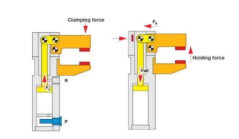
Forces acting in the clamp and rest unit:
while designing a clamp unit 2 forces are considered that act in clamp unit,
1. Clamping force
2. Holding force
1. Clamping force:
It signifies the force applied to the workpiece by the drive mechanism via the clamp arm during gripping or clamping operations.
2. Holding force:
- Holding force, on the other hand, denotes the maximum force after locking the knee-lever (over centre position, that can be applied by the workpiece on the gripper/clamp arm without destroying the mechanism.
- Therefore, particular attention must be paid to the maximum holding force when, for example during the production process (welding, bonding), there is a possibility of distortion of the component or if the clamp arm is used as a fixed stop.
- If the holding force specified in the technical details is exceeded, this will inevitably result in the destruction of the
mechanism, the clamp arm or the bearing position.
Finding the outreach of clamp arm
By measuring the distance between the pivot center of the cylinder and the center of the clamping mylars one can get the outreach of the clamp arm.
The respective outreach of the clamp arm taken from the clamp unit used in this project are as follows,
1. P001_Z03_ST010_03_00_CLAMP_UNIT - an outreach of clamp arm is 164mm.
2. P001_Z03_ST010_04_00_CLAMP_UNIT - an outreach of clamp arm is 120mm.
3. P001_Z03_ST010_05_00_CLAMP_UNIT - an outreach of clamp arm is 174mm.
By relating the sheet thickness and the outreach as shown above, now the selection of power clamp is done as per our requirements.
The bore capacity of clamp cylinders is found and the power clamp cylinder is selected.
Orienting:
The fixture should orient the work piece such that all the operations to be performed on it are within the reach of the work piece.
Clamping:
A clamp is a fastening device used to hold or secure objects tightly together to prevent movement or separation through the application of inward pressure. There are many types of clamps available for many different purposes. Some are temporary, as used to position components while fixing them together, others are intended to be permanent.
CLAMPING GUIDELINES:
Locating the work piece is the first basic function of a jig or fixture. Once located, the work piece must also be held to prevent movement during the operational cycle. The process of holding the position of the work piece in the jig or fixture is called clamping. The primary devices used for holding a work piece are clamps. To perform properly, both the clamping devices and their location on the work holder must be carefully selected.
Factors in Selecting Clamps:
Clamps serve two primary functions.
- They must hold the work piece against its locators.
- The clamps must prevent movement of the work piece.
Procedure of Clamping the work piece to the Panel:
- Place the work piece, supply air at clamp side without installing clamping block, operate the clamp arm to the end of clamp.
- Under the above conditions, adjust shim so that the space between the work piece and the clamping block is about 0.5 mm. Theoretically there is no clamping force for holding a work piece under this condition.
- In order to generate clamping force from the state described in step B, insert additional shim. The thickness of the shim differs depending on the arm length and pressure, so please refer to the graph on front matter 3 as a guide. About 10% error may occur due to the difference in tolerance of the clamp cylinder body.
- Clamping Force:
- Clamping Force is the force required to hold a part against the locators. Clamping prevents the part from shifting or being pulled from the jig or fixture during the machining operation. The type and amount of holding force needed to hold a part is usually determined by the tool forces working on the part and how the part is positioned in the tool. Sometimes the operation being performed is a factor. Clamping Pressure, as a general rule, should only be enough to hold the part against the locators. The locators should resist the bulk of the thrust. If a part must be clamped with great deal of pressure, the tool should be redesigned so that the tool thrust is directed at the locators and the locators and the tool body. Clamps must never be expected to hold all of the tool thrust.
- Relation between shim thickness and clamping force:
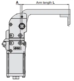
- When a shim that exceeds the clamping force peak plotted on the graph is inserted, the self-locking mechanism doesn't work. Insert a shim with appropriate thickness. Arm length “L” indicates the distance between the clamp arm shaft and the clamping position.
- For distance “A” between knock positioning pinhole and clamp arm shaft.
CONSIDERATIONS TO BE TAKEN WHILE DESIGNING A REST UNIT OR A CLAMP UNIT:
Considerations to be taken while designing a Rest Unit or a Clamp unit are:
Study of process planning document:
Process document should contain following information, which are necessary to design clamp unit.
- No of sheet metal panels to be welded.
- Total no of spots.
- Welding gun details if it is already recommended by process engineer study it in details like shape and its type.
- Study the PLP (Principle Location Points) data along with the nearby spot data.
Height Selection:
Take an overview of the working height if we have manual welding. For robotic welding also its important to see the working height in consideration of the robotic gun, turn table height if manual loading is done.
Gun Placement:
Put the proper gun at the spot location. Do the proper gun study and place the gun as per the GEO or re-spot decision and operator approach. Once basic gun is placed considering the throat depth and throat gap start building the clamp and rest block at the PLP.
Panel section creation:
Take a section at PLP either in clamp opening direction or normal direction. Sections should be normal to base. Panel section through X, Y or Z direction passing through PL. Section will help in finalizing the shape of clamp and rest block. Most importantly used for finalization of gun shape.
Finalization of a base plate:
Consider following things before deciding the base plate.
- Height of maximum and minimum weld spot from the floor.
- No gun arm should touch the base plate.
- Operator ergonomic while accessing all the spots.
Construction of Rest and Clamp Block:
If standard Mylar has to be used then select the proper blank size as per the requirement consider 0.5 mm above the panel.
Clamp cylinder selection:
Select the clamping cylinder as per the pivot point distance from the PLP. You may choose various cylinder 50 Dia, 63Dia, 80 Dia.as per the requirement.
Clamp and Rest block creation:
Create clamp or rest block as per the company guidelines.
Many companies have size of clamp block as 20x20 mm and no of mounting screws and dowels. Many use 20x20 size rest or clamp block with one screw and 2 dowels or few uses with 2 screw and 2 dowels. Materials of clamp block and rest block to be decided as per the A class panel or B class. Most of exterior panel holding Teflon material is used. Otherwise, steel is used with heat treatment. Sometimes Aluminium blocks are also used. Start construction of mounting plate or fabrication structure as per the company standard to make the connection with the base plate.
Riser:
As per OEM, Tier 1 standard use the different standards mounting risers. Do not forgot to add the 5 mm shim.
Rough Locator or position sensor mounted on clamp unit:
If you are combining rough locator or part sensor bracket along with the clamp unit. Take necessary care means distance of rough locator from panel.
Hardware:
Add all the hardware screws, dowels and washer as per the size.
Clamp Open Position:
Check all the clamp open, gun open position and ensure that there is fouling with panels or any other surrounding units.
Rest Unit:
These units are used to rest the panel. Take an overview of the working height if you're having manual welding. For robotic welding also it's important to see the working height in consideration of the robotic gun, turn table height if manual loading is done. Put the proper gun at the spot location for all the spots near the rest unit. If process engineer has gun shape stick to X, C, Y type of gun. Do the proper gun study and place the gun as per the Geo or re-spot decision and operator approach. Once basic gun is placed considering the throat depth and throat gap start building the clamp and rest block at the PLP.
Panel section creation:
Take a section at PLP either in clamp opening direction or normal direction Sections should be normal to base. Panel section through X, Y or Z direction passing through PLP. Section will help in finalizing the shape of clamp and rest block. Most importantly used for finalization of gun shape. Finalization of a base plate should consider following things before deciding the base plate. Height of maximum and minimum weld spot from the floor. No gun arm should touch the base plate Operator ergonomic while accessing all the spots
Construction of Rest Block:
If standard Mylar has to be used then select the proper blank size as per the requirement consider 0.5 mm above the panel. As per OEM, Tier 1 standard use the different standards mounting risers. Do not forgot to add the 5mm shim. If you are combining rough locator or part sensor bracket along with the rest unit. Take necessary care means distance of rough locator from panel. In the process of manufacturing, we use Steel Aluminium, S-grun, and Plastics. And hardening is necessary in manufacturing Mylar and Pin.
PLP Location & Clamp plan:
PLP (Principle Locating Points): Principle locating points are the points which are used for the accurate location of the panels sub-assemblies to maintain the geometry of the assembly. There are lots of holes on the panel which are not accurate due to stamping operations. So, the PLP are defined in the drawings. The PLP holes must be very much precise.
Clamp Plan: Clamp plan provides the information of location of pins, Rest units, clamp unit, Dumps etc. It is the important input from customer. The clamp plan/position should not be changed without the knowledge of customers it gives the detail of the exact position of the clamping units by mentioning a co-ordinate in the particular position
Power clamp Cylinders:
Power Cylinder has been designed to operate as an actuator in a pneumatic control system to position the final control elements in accordance with the controller signal. Pneumatic cylinder are mechanical devices which use the power of compressed gas to produce a force in a reciprocating linear motion like hydraulic cylinders.
Average Clamping force(Fs) = 1200N (for the size of 50 bore dia and mean length of clamp arm)
Types of Rest Units:
Parts in clamp unit:
1. Finger /clamp mylar:
- It is a NC block mounted on the clamp arm of the cylinder.
- It is used for clamping / holding the car panel.It presses the car panel towards the rest.
- It presses the car panel towards the rest.
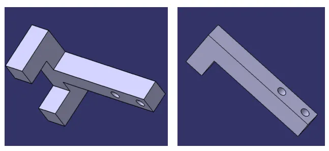
2. Backup / Rest Mylar:
- It is a NC block fixed to the unit to support the car panel.
- It helps in resisting the clamping force of cylinder onto the panel, thus clamping is achieved
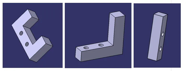
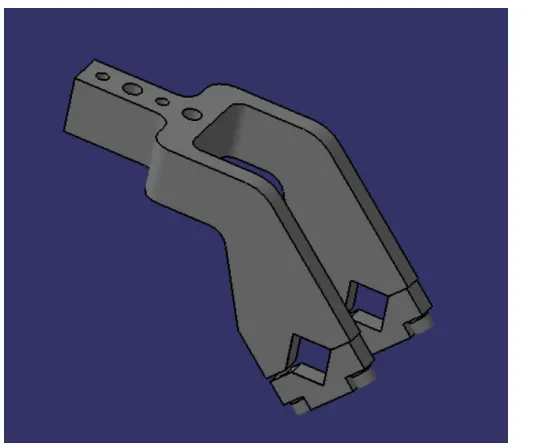
3. Clamp arm:
- Clamp arm is a part of the clamp cylinder and it is a bought out part which is available in some standards.
- All the moveable parts in teh clamp unit are fixed to the clamp arm.
- Clamp arm is different for different bore size of cylinder, it is available in different hole pitch.
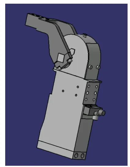
4. Clamp cylinder:
- Clamp cylinder is a pneumatic device which works with the flow of pressurised air.
- Clamp cylinder is a brought out part and some manufacturers are destaco, tuenkers, etc.,
- The clamping cylinder is used to open and close the moving part in the clamp unit.
- It is generally available in 40, 50, 63 and 80 bore capacity.
- Clamp cylinder opens upto 135 degree for horizontal clamp mounting and it opens upto 105 degree for vertical clamping.
Riser: It is a part on which all the parts are mounted and it is mounted on the base plate of the fixture.
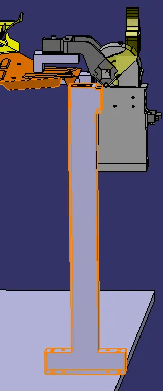
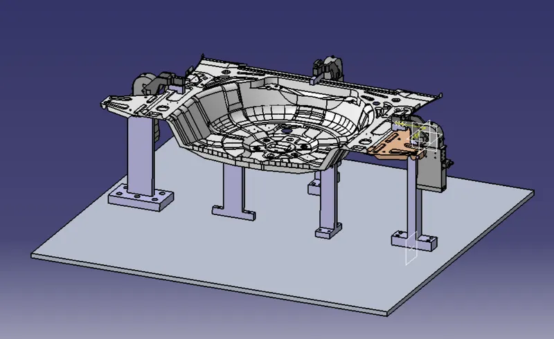
Final View of PIN_CLAMP_UNIT
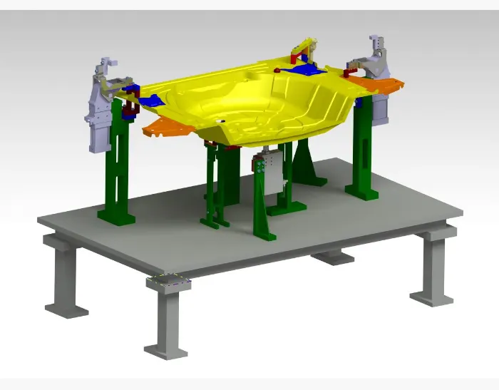
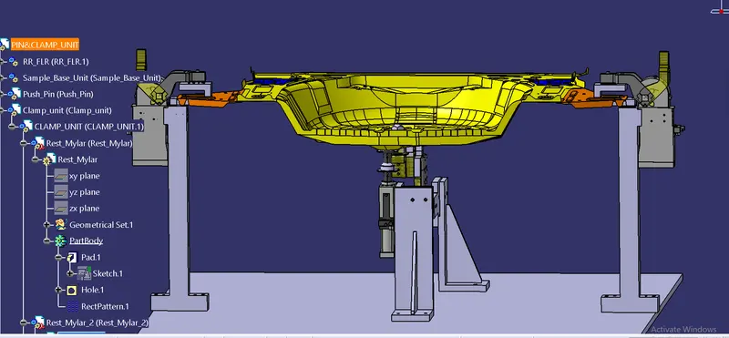
The fixture should locate the work piece such that all the operations to be performed on it are performed without any problem and all of them are performed effectively.