Week 5 - Rayleigh Taylor Instability
AIM: To study the rayleigh taylor instability
Rayleigh taylor instability is defined as the mixing of two phases of different density materials, which are earlier is in the position such that, higher density material lies at the top of the lower density materials, and once we initialte the simulation, under the effect of gravity we had observed the mixing of phases, such that, lighter density material rushed into the zone of heavy density material, and at the end of the simulation, the lighter density material settled at the top, while the lower density material settled at the bottom.
Examples:
- Water suspended above oil
- Atmospheric nuclear explosion
- Supernova explosion (core gas accelerated into denser shell gas)
- Nuclear explosion
- Volcanic eruption
CASE I: Base mesh 0.5mm
Procedure:
- Initially we create the required surface of 20x20 (two slabs), and after pulling the geometry, an sub-named into component we share the topology.
- asd
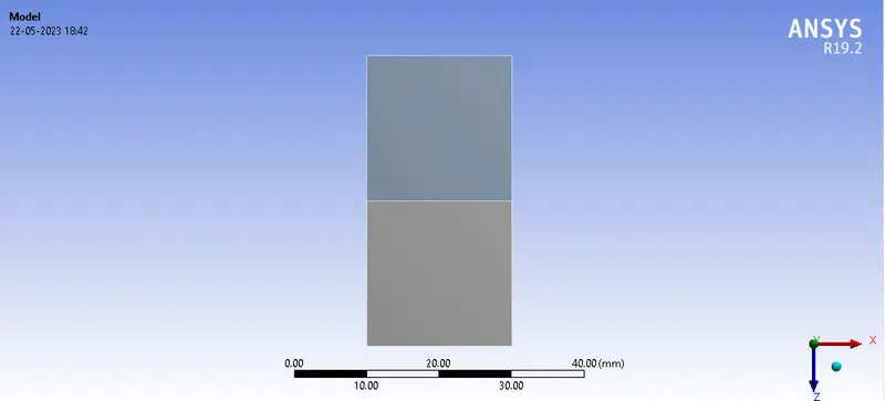
Fig: Model View
Following are the mesh view:
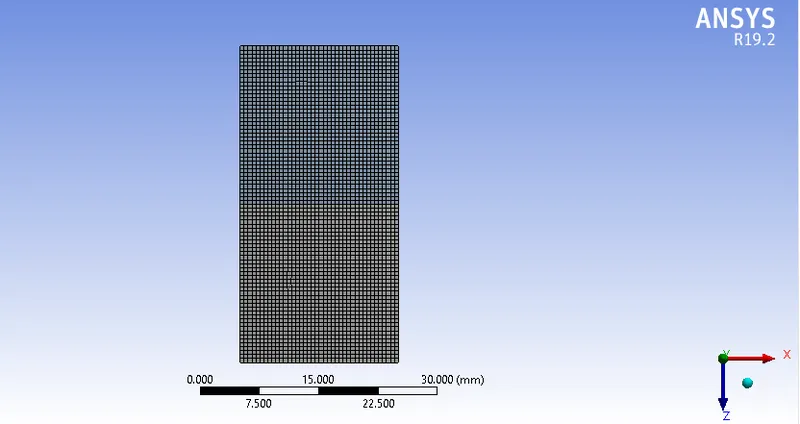
Mesh details are:
Element Size: 0.5mm
Total Nodes:3321
Total Elements:3200
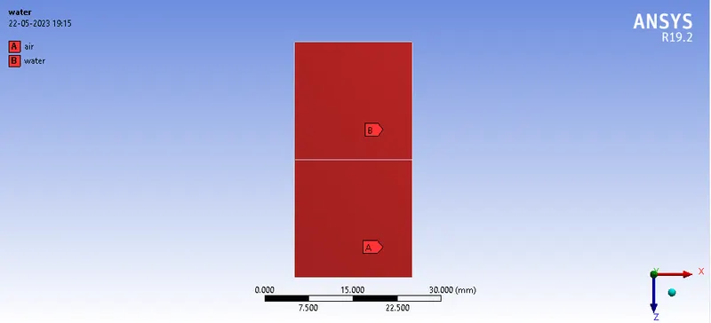
Fig: Indicating name selection
In solver type, we had used, pressure based, transient study,
Under the setting up physics tab, we had used the multiphase, implicit function for simulation.
following are the materials which we had used for simulation:
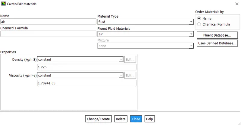
Fig: Indicating air properties
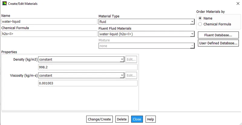
Fig: Indicating water properties
After that, we patch the phases, via volumefraction as variable assigned as 0 for air, and 1 for water;
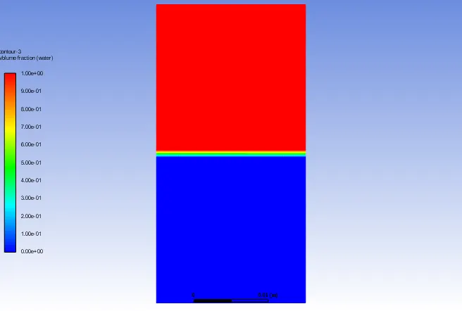
Fig: Indicates patching (before starting of simulation)
Google Drive Link For The Animation:
https://drive.google.com/drive/folders/11KlqnYX4192_5LvIvNFOJz8GpKwCbHZL?usp=share_link
CASE II: Finer Mesh:
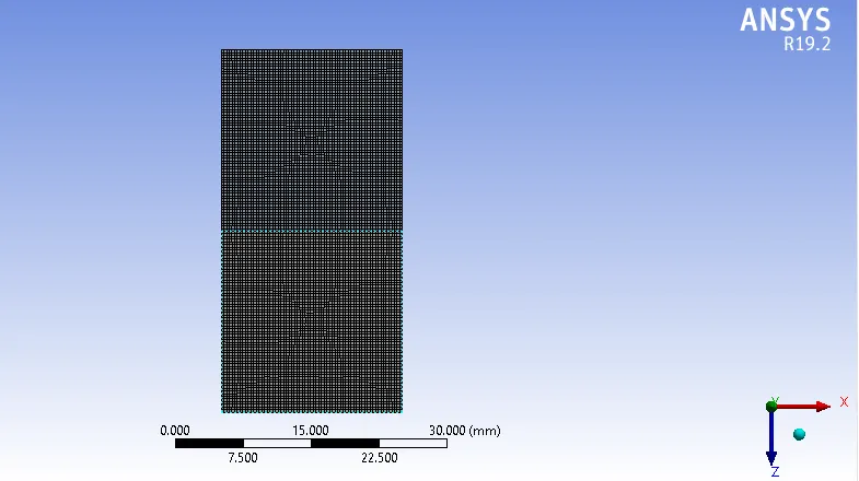
Fig: Indicate Mesh View
Details of mesh are as follows:
Element Size: 0.3mm
Total Nodes:9180
Total Elements:8978
Material properties are same as Case I, that is , air & water.
G-drive link for the animation:
https://drive.google.com/drive/folders/1PCb_g-Ok4MsYCkDRNf7Pmca6Iy9po7pN?usp=share_link
CASE III: Finer Mesh (0.3mm, with material as water & user defined)
mesh view is same as case II, the only difference from case II is the material properties, in this case I had take water and user defined material;
the property of user defined material are as follows:
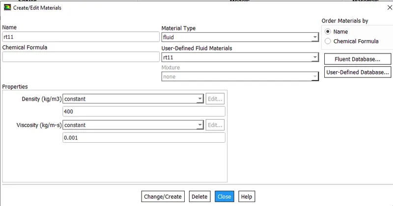
G-drive link for the animation is:
https://drive.google.com/drive/folders/1nzgl7agMQ-PJT3KXWagqOud3Ls6hrh6n?usp=share_link
ATWOOD NUMBER:
it is a dimensionaless number, which is generally used to analyse the hydrodynamic instabilities,
the mathematical formula of the such are:
AN=(p1-p2)/(p1+p2)
where, p1= density of heavier fluid, p2= density of lighter fluid.
significance of atwood number:
when it is close to zero, it indicate the Rayleigh taylor instability of asymetric finger kind of fluid
while when it is close to 1, it indicate the rayleigh taylor instability takes the large bubble formation knd of fluid,
the following are the value of above cases:
| CASE | STATE | MESH SIZE (mm) | PHASE | DENSITY OF PHASE 1 | DENSITY OF PHASE 2 | ATWOOD NO. | FORMULA |
| II | TRANSIENT | 0.3 | PHASE 1 WATER & PHASE 2 AIR | 998.2 | 1.225 | 0.998 | (p1-p2)/(p1+p2) |
| III | TRANSIENT | 0.3 | PHASE 1 WATER & PHASE 2 USER-DEFINED | 998.2 | 400 |
0.42 |
|
Thus, it is evident from the above analysis that, as the value of atwood number is close to 1, it gives large bubble formation, prior to the formation of mushroom head shape (assymetrical in nature) at an accelerating rate leads to non linear growth,
|