Week - 5 - Modelling Spotwelds
AIM : Modelling of spotweld using beam and solid element and analyzing their behaviour under uniaxial load
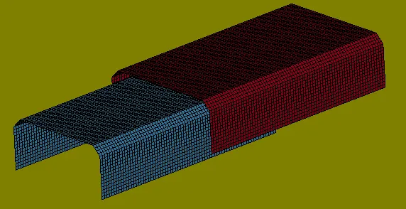
Different spotweld techniques are:
- Using Beam element and tied edge to surface contact
- Using constraint spotweld
- Using constraint generalized
- Using Solid element and contact spotweld
Procedure for Spot weld using Beam element and tied edge to surface contact:
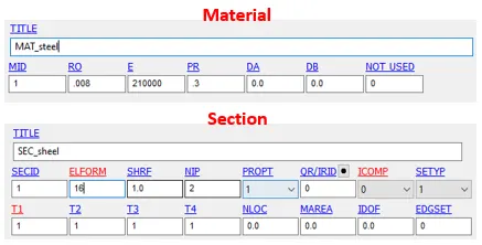
1. First material and section to both sheet metal parts is assigned. Unit system used here is gm-mm-ms. For the section ELFORM16 is used for full integration of sheel element. 1mm Thiskness is given.
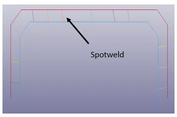
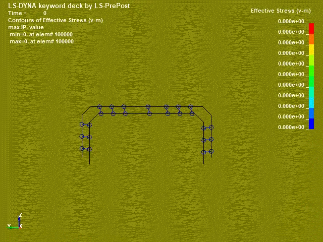
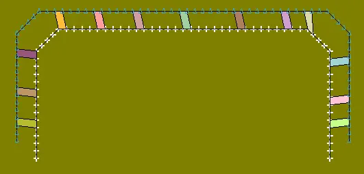
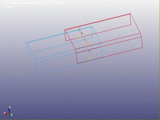
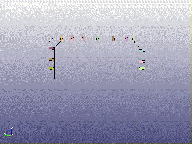
2. Now Beam element is generated at different locations. Total 13 beam elements are formed. Both material and section is assigned to beam elements.
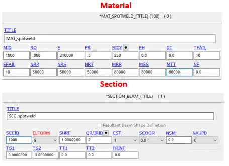
- Spotweld material is assigned to element and in beam section ELFORM 9 is selected because for shell element it give good result (mention in tutorial book).
- Initially, random Tfail, normal force and shear force values are given to check the failure values.
- In section CST is choosen 1 (tubular) and inner diameter value is set to 0 i.e. TT1 and TT2. And upper and lower diameter is set to 3 (TS1 & TS2)
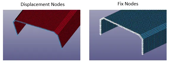
3. Now two node sets are created. One to fix the one end another to give displacement to that.
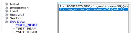
- For the fix node set, elements are constraint in all degree of freedom

- Before giving displacement a displacement is generated . 20mm dispacement is given in 20.5 ms.
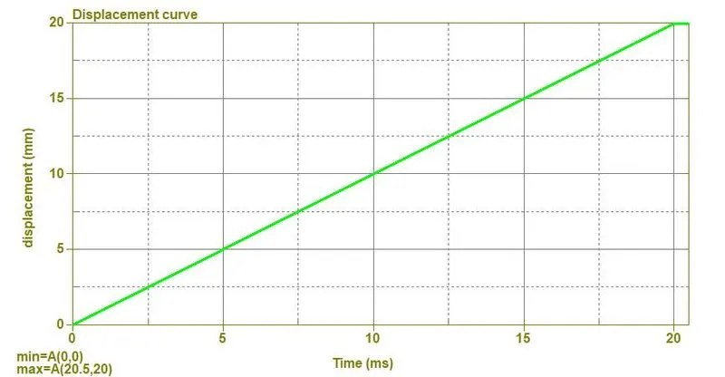
- For the displacement set, DOF in x-axis (axis of movement) is set i.e. (1) and displacement flag is given i.e. VAD = 2.

4. Now contacts are given. Here two type of contacts are used which are
- Automatic single surface contact : This is given when their is chance of interference of two or more bodies during deformation or motion. To do so, a part set is generated which include both shell parts. Both are given slave ID.
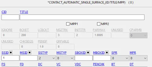
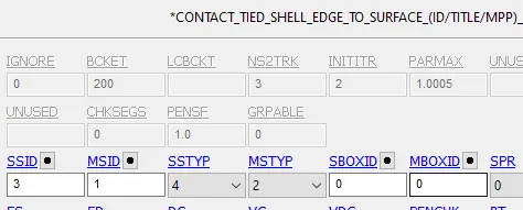
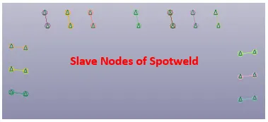
- Tied shell edge to surface : This is spotweld contact type. Here a node set for spot weld node is created. And spot weld is given slave ID and shell parts are given master ID.
5. Now termination time is set to 20ms. Also from the control deck energy is also selected to calculate the hourglass energy.
6. From the database deck
- binary d3plot
- MATSUM
- GLSTAT
- SECFORC - For this first section plane is created at the spotweld location.
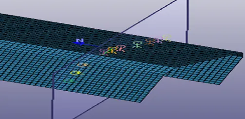
- SWFORC - to calculate the axial and shear force in spot weld.
- NODOUT - for this first history node is created.
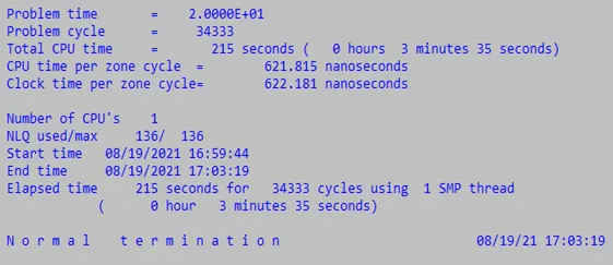
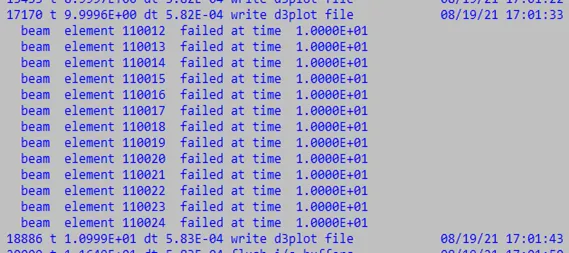
Completion time and element failure time
Here elements are failed exactly at mid of simulation which represent that our model is correct. Total simulation time is 215 seconds.
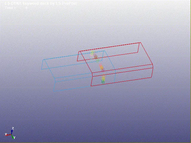
Animation of Beam element spotweld
Procedure for Spot weld using solid element and spotweld contact:
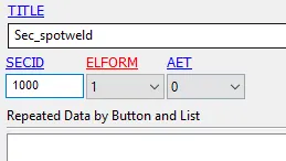
Here, only difference exists in element type selection and Section ELFORM selection rest procedure is same. ELFORM 1 is selected for solid element and instead of beam element here we create a hexa element.
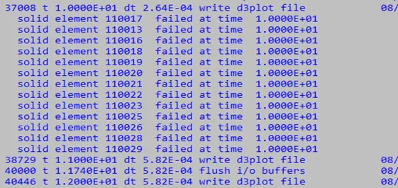
Completion time and element failure time
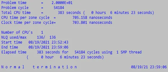
Here elements are failed exactly at mid of simulation which represent that our model is correct. Total simulation time is 383 seconds.
Animation of solid element spotweld
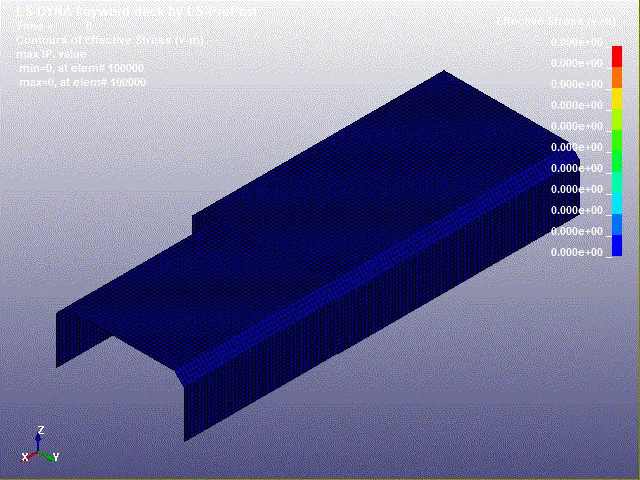
Results and discussion :
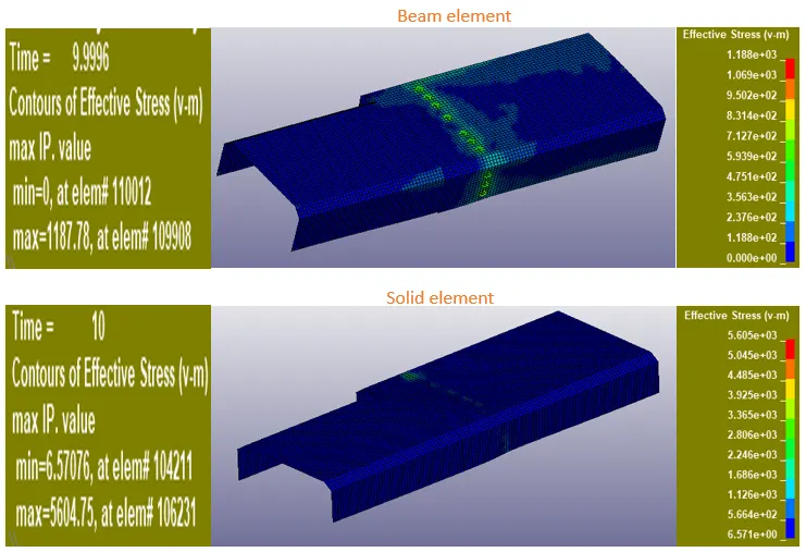
1. Maximum stress plots :
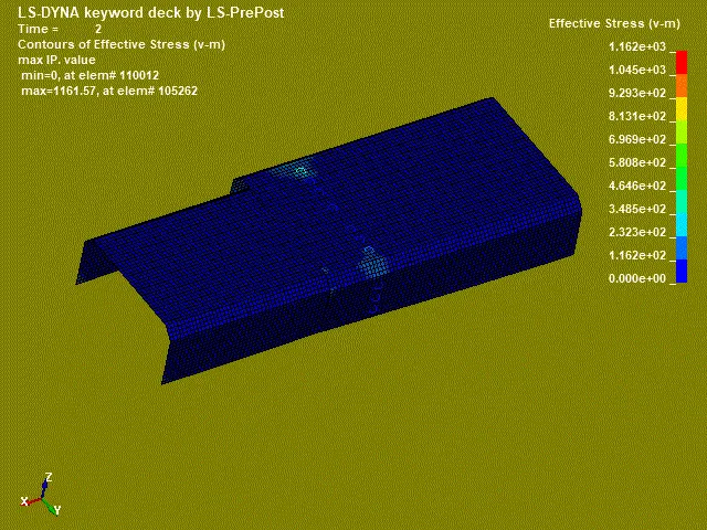
Stress generated in solid elements is very high compaired to the beam element which means solid elements have more capacity to absorb energy.

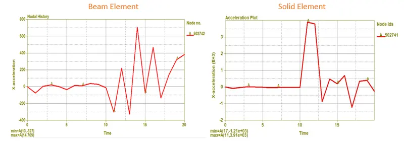
2. Acceleration plots
In both the cases until 10ms acceleration is almost zero. After spotweld breakage beam element has max acceleration of 709 mm/ms2 and solid element node has 3910 mm/ms2.
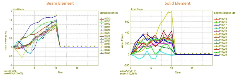
3. Axial force plots
At 10ms axial force drops in both cases which shows our weld failed due to maximum axial force. WE have 13 spot welds each give different result due to different location orientation of these welds.

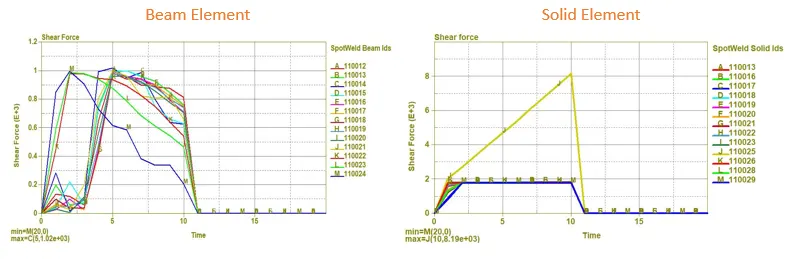
4. Shear force plots
As problem with beam element spot weld is, it can only take load in 1-dir. So it does not display correct shear load behavior, which can be seen in below figure as beam element has very less shear load than solid one.

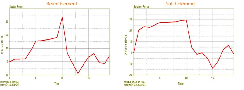
5. Section force plot
Here more force is generated in beam element at failure point, however throughout the displacement, solid element offer more resistance than beam element as from time 0 ms to 9.5 ms higher force is generated in solid element.

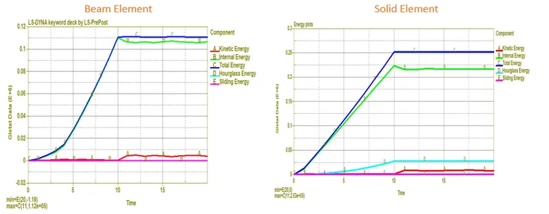
6. Energy plot
More energy is generated in solid element, as it absorbs more energy due to which stress in them is also high. As full integration element formulation is used houglass energy is veru less in both the cases. Kinetic energy is used to break the weld, after 10m weld break and upper plate drags away, so kinetic energy is showing agter 10 ms.
Conclusion:
- Solid element give better result for shear force, as beam element can onlt take load in 1 dir.
- Internal energy is very high in solid element than beam.
- Stress generated in solid element is also higher.
- Solid element offer more resistance to breakage than beam.
Learning Outcomes:
- leared different ways to model spotweld.
- calibration of spotweld material after failure.