Week - 5 - Modelling Spotwelds
Report Week 5 Modeling Spotweld
Aim: perform simulation of spotweld using beam and solid element, simulate crash movement and view results.
Procedure:
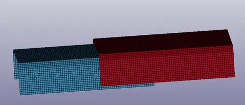
Open keyword file, we can see two shell element.
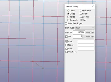
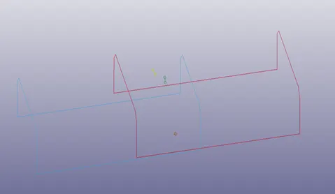
Create another 3 spotweld beam element in 3 parts
Assign material for parts:
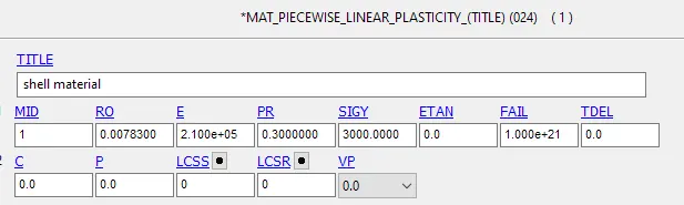
For shell element use mat 24:
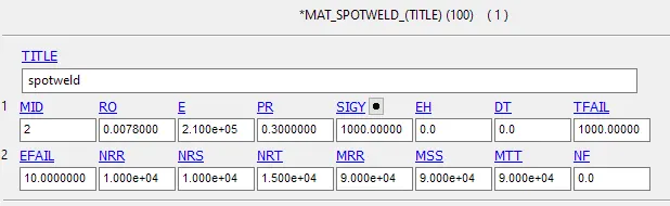
For spotweld, use material 100, spotweld element:
Assign section for parts:
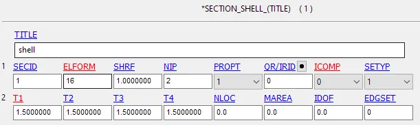
For shell element, give a thickness 1.5mm, elform 16:
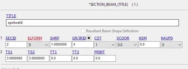
For beam element, elform must choose 9 for spotweld:
Then create contact:
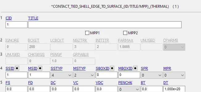
Tied_shell_edge_to_surface contact:
Self contact (single surface):
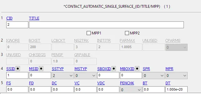
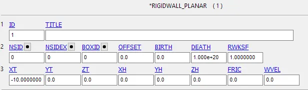
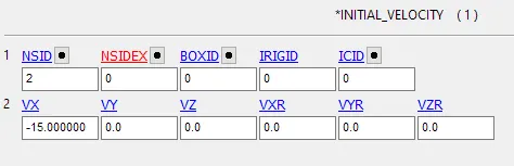
Create a rigid wall, give all parts a initial velocity 15mm/s towards wall
Set up control- termination 10s

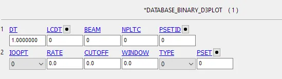
Database
There is another case: solid spotweld
The difference is to create spotweld with Hexa:
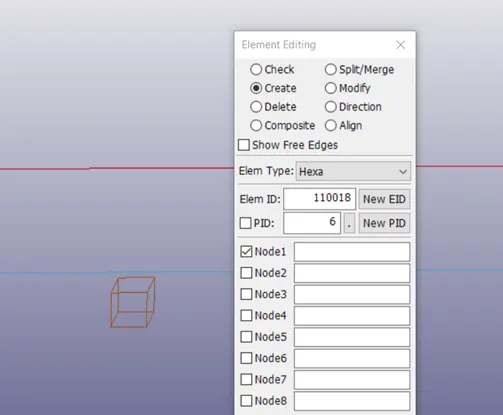
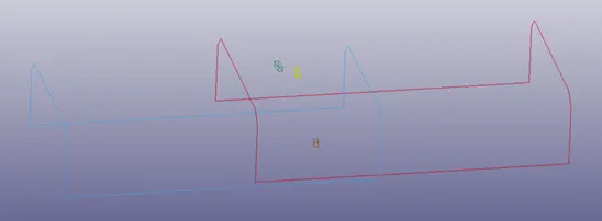
Material for spotweld is the same, but section is different:

Contact is different:
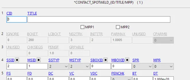
Then run the simulation:
beam element:
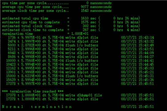
solid element:
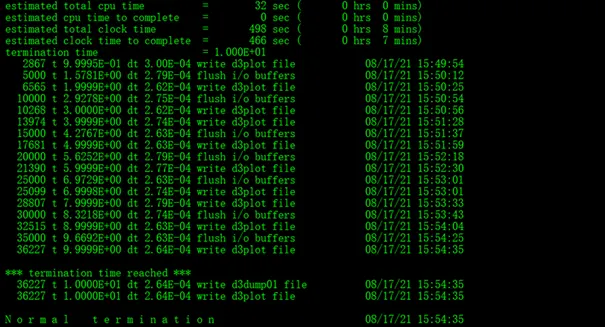
Results:
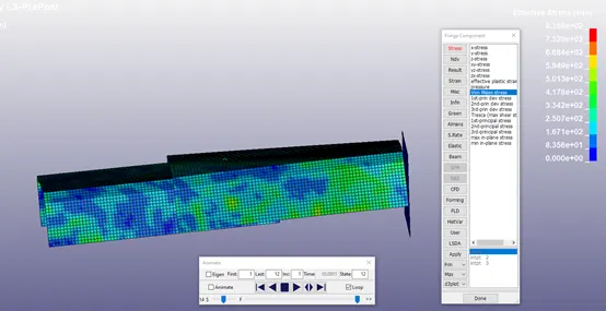
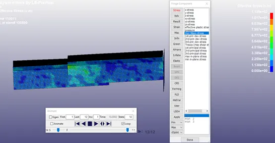
Von Mise stress:
Beam:
Solid:
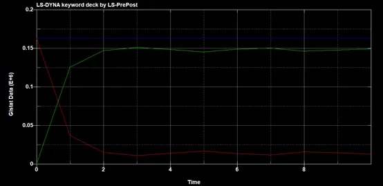
Energy:
beam:
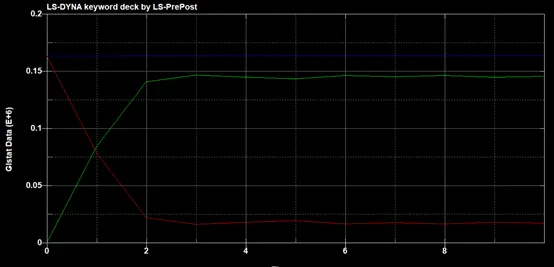
solid:
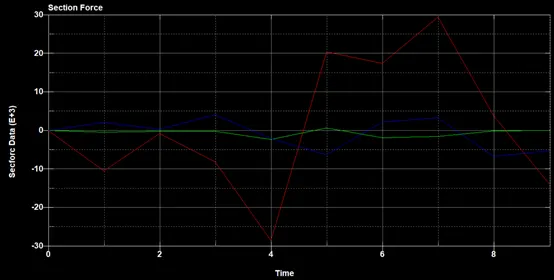
Section force x,y,z on spotweld:
Beam:
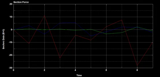
solid:
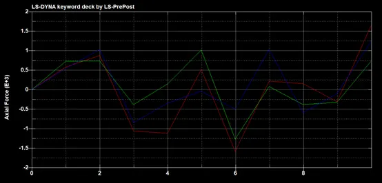
Axial force on three spotweld:
Beam:
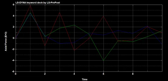
Solid:
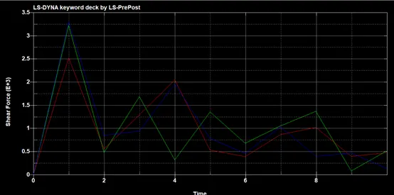
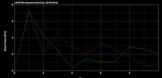
Shear force on three spotweld:
Beam:
Solid:
Conclusion:
Spotweld are simulated with beam element and solid element. Solid element have more stress than beam element with other conditions are the same. The contour plot for x,y,x force, axial force and shear force on spotweld are plotted. In this case, we don’t see failure on spotweld.