Week - 5 - Modelling Spotwelds
AIM: To model spotweld for the given assembly by using Beam and Solid elements.
PROCEDURE:
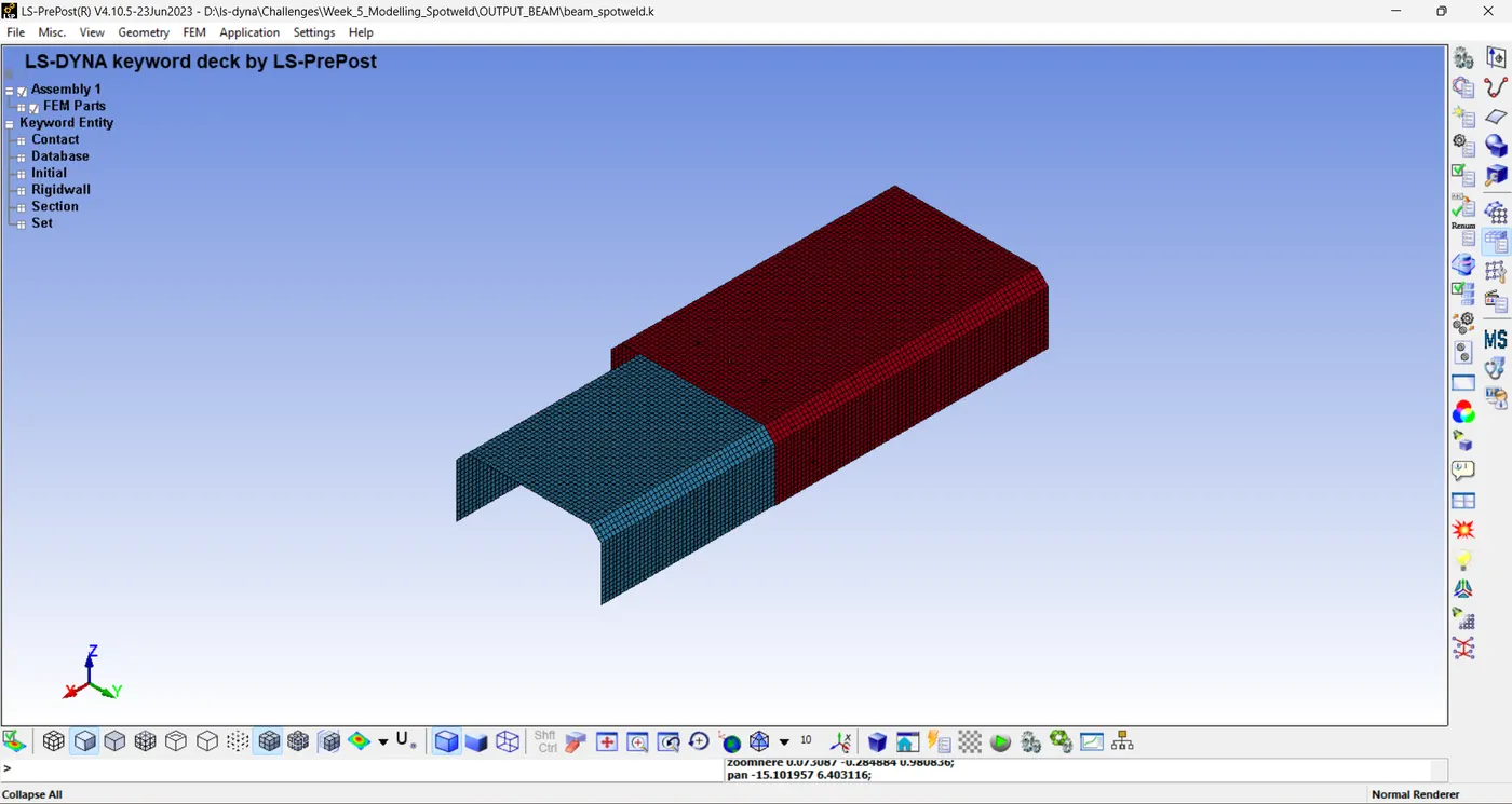
STEP 1: OPEN THE MODEL.
STEP 2: DEFINE SECTION CARD FOR SHEET.
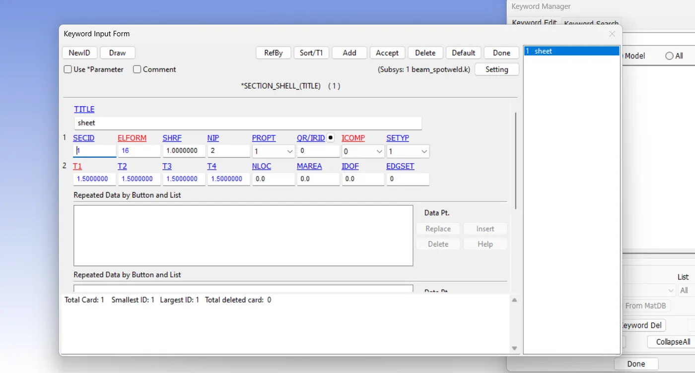
ELFORM= 16
THICKNESS= 1.5mm
STEP 3: DEFINE MATERIAL FOR TWO SHEET.
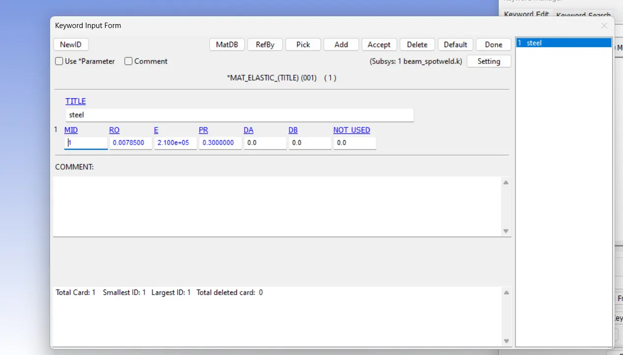
RO= 0.0078500
E= 2.10E5
PR= 0.3
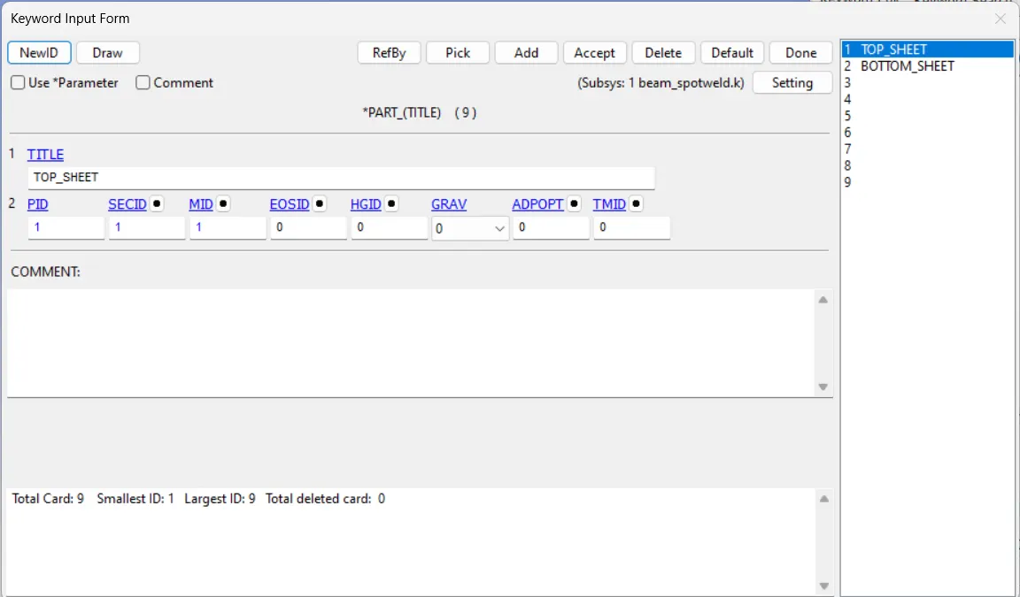
STEP 4: DEFINE PART ID FOR SHEET.
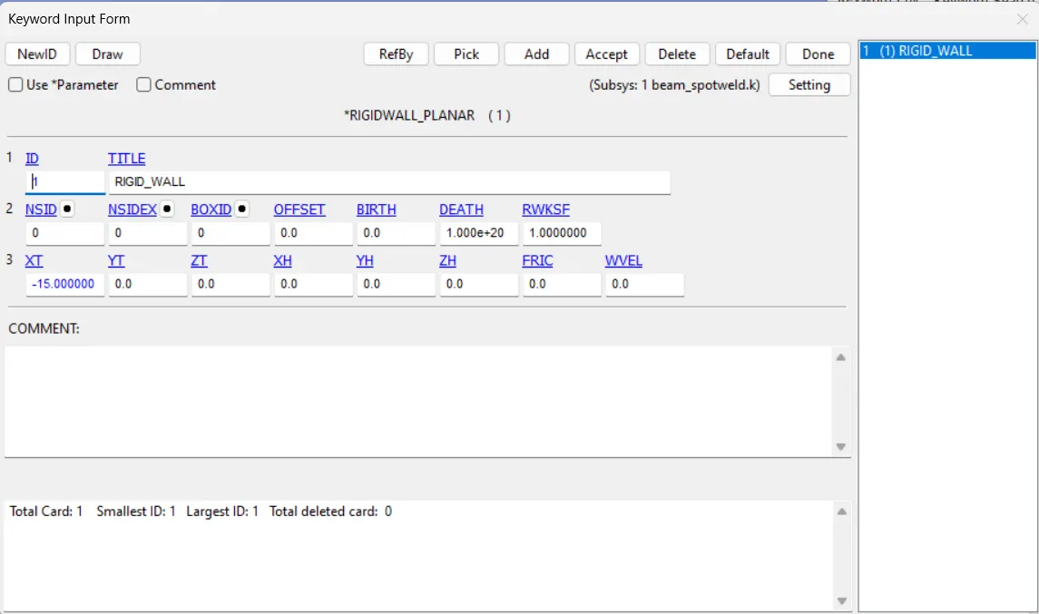
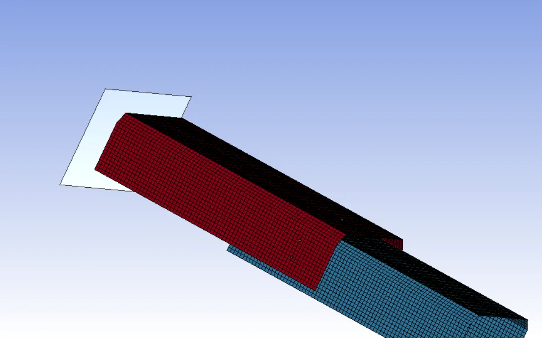
STEP 5: CREATE RIGID WALL.
The rigid wall created in front of top sheet metal part 15mm away.
Keyword manager > All > Rigid wall > Planar
here, XT= -15
NSID= 0 , NSIDEX= 0
STEP 6: DEFINE VELOCITY TO SHEET.
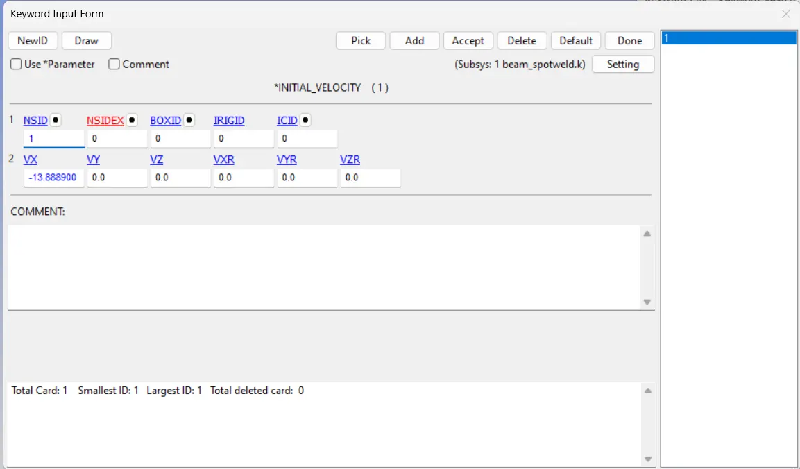
Here the velocity is defining for two metal sheets. So we want to define velocity to all nodes of the sheet.
Create Entity > Set Data > *SET_NODES
Select the nodes from the two parts by using pick by part option.
Then go to All > INITIAL > VELOCITY
Give the NSID and VX= -13.8889
50 KMPH= 13.8889 MPS
STEP 7: CREATING SPOTWELD BY BEAM ELEMENT.
To represent as a beam element, we can use *CONTACT_TIED_SHELL_EDGE_TO_SURFACE
Element and mesh > Element Generation > Beam
Beam by : Two_node_sets
Pick the desired nodes from bottom and top sheet metal.
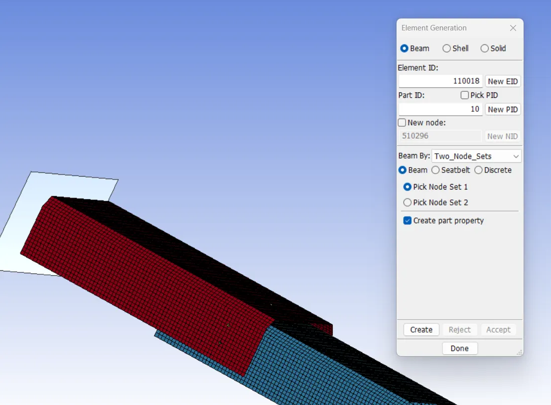
Here the fact is that automatically a SECTION card ie, *SECTION_BEAM and the material card ie, *MAT_CABLE_DISCRETE_BEAM are created and we need to delete these card and assign our required material and section card.
STEP 8: DEFINE MATERIAL FOR BEAM.
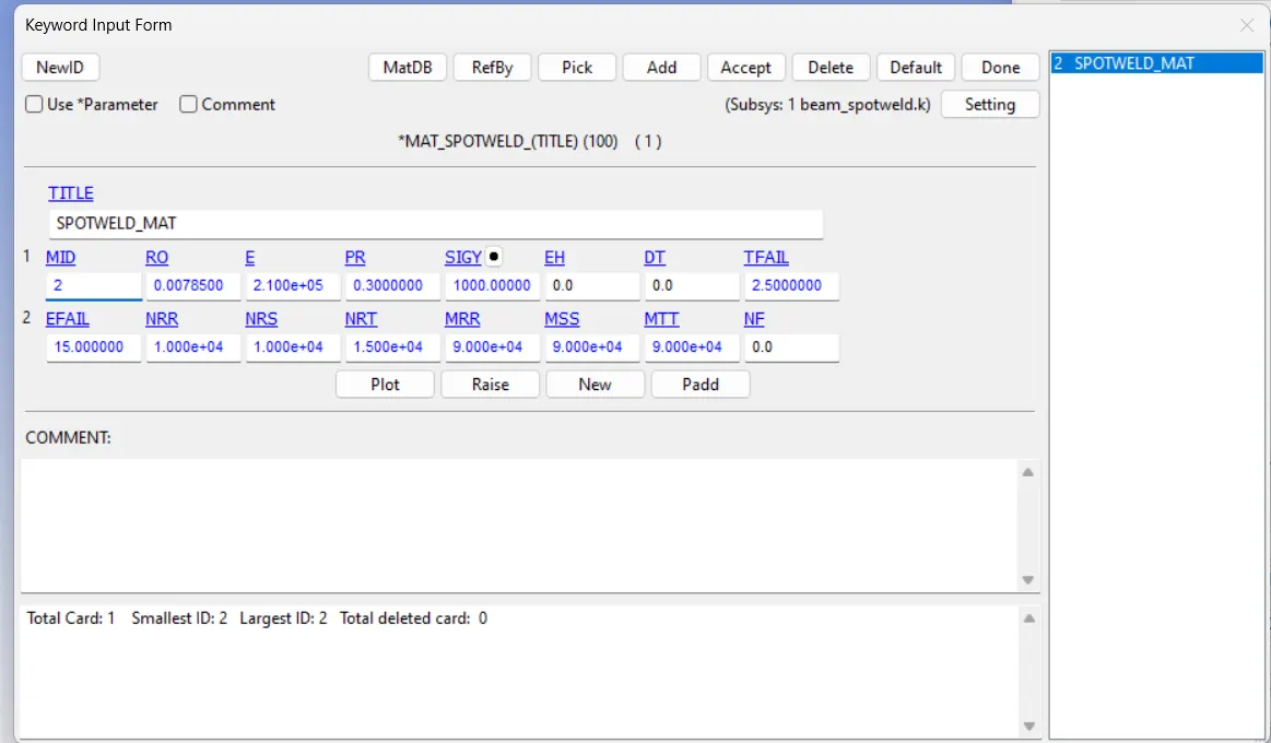
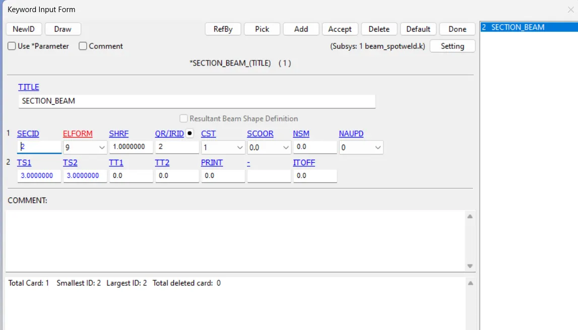
STEP 9: DEFINE SECTION FOR BEAM.
ELFORM= 9
CST= tubular, THICHNESS= 3mm
STEP 10: DEFINE PART FOR BEAM
Add the SECTION ID and MATERIAL ID to PART card.
STEP 11: DEFINE CONTACT FOR BEAM ELEMENT.
For beam element the contact type is *CONTACT_TIED_SHELL_EDGE_TO_SURFACE.
Here the master set id will be part id and Slave set id will be nodes of beam weld element.
For defining the Slave set select beam nodes as to create the set and the step is,
Entity create > setData > *SET_NODE
For defining the Master set select both the metal sheet parts and the step is,
Entity create > setData > *SET_PART.
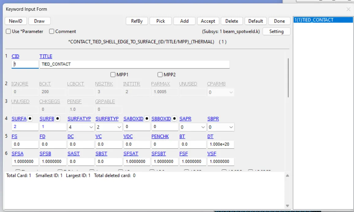
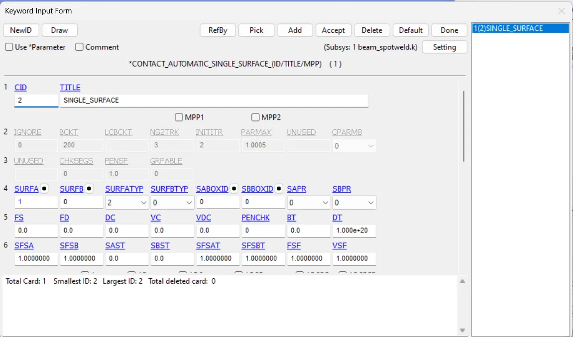
Also we need to create an AUTOMATIC_SINGLE_SURFACE contact card for the parts to ensure that after the spotweld breaks the parts come to each other they should not penetrate, Here the parts set are the slave.
SPOTWELD MODELING BY USING SOLID ELEMENT:
ELEMENT AND MESH > ELEMENT EDITING > CREATE
TYPE: HEXA
Pick the four desired nodes from the bottom and top sheet metal.
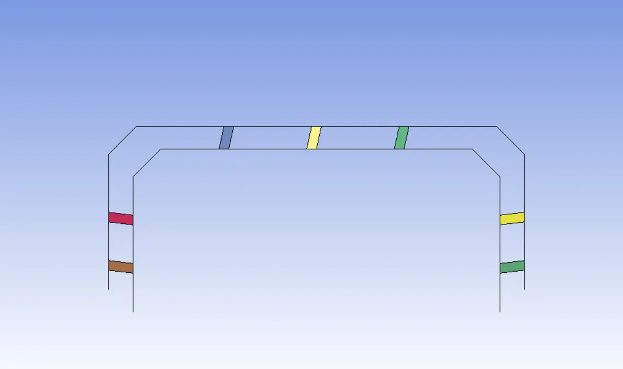
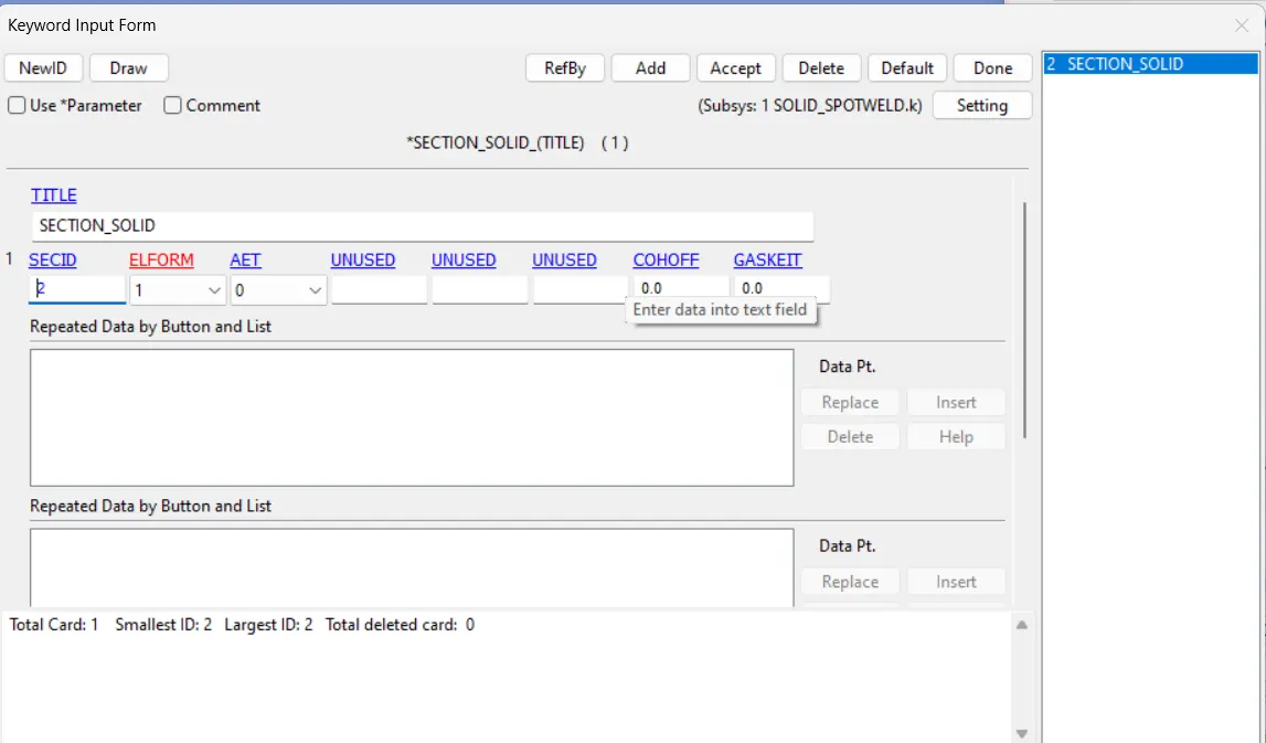
STEP :DEFINE SECTION CARD FOR SOLID ELEMENT
ELFORM = 1
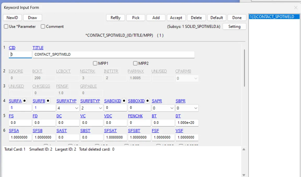
STEP : DEFINE CONTACT CARD FOR SOLID ELEMENT
*CONTACT_SPOTWELD
Here Master set id will be Part id, Slave set id will be nodes of solid weld element.
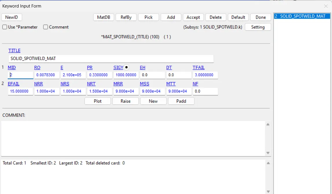
STEP : DEFINE MATERIAL FOR SOLID SPOTWELD
Here we are using *MAT_100
STEP : DEFINE PART CARD FOR SOLID SPOTWELD ELEMENT.
Add the section id and material id to PART card.
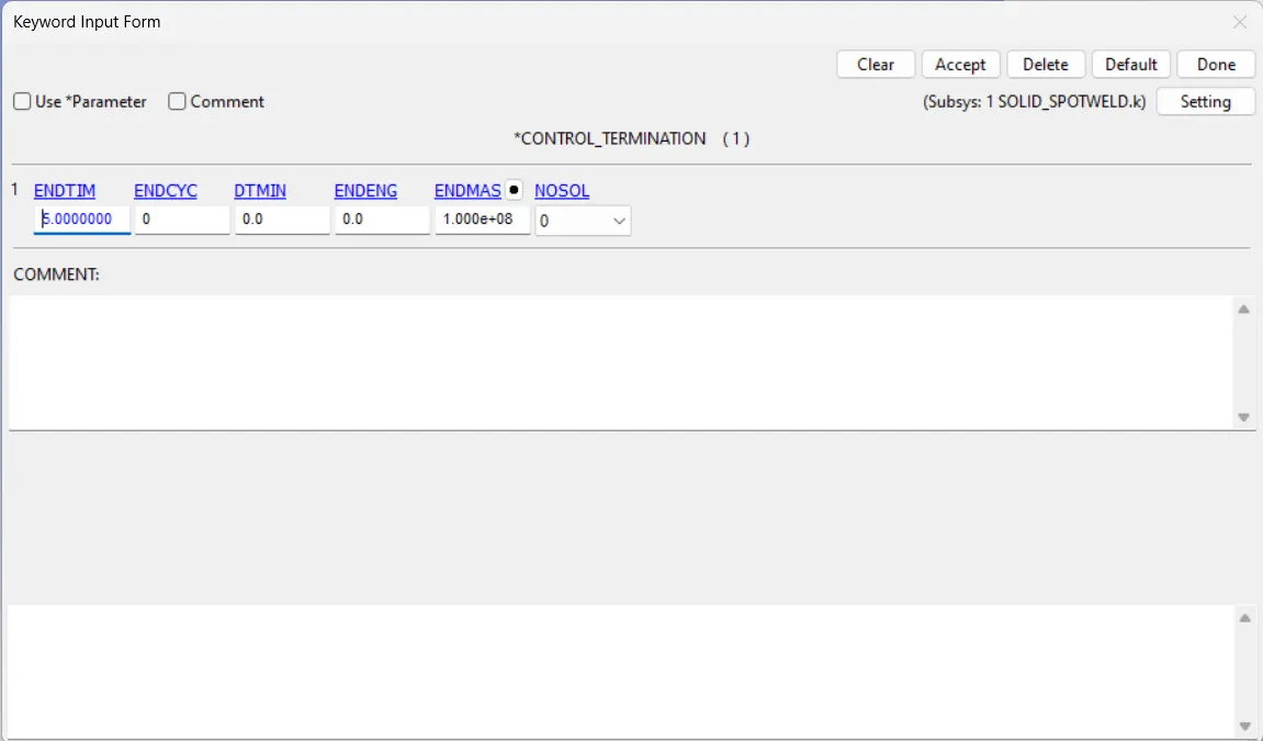
STEP: DEFINE TERMINATION TIME.
ENDTIM= 5ms
STEP : DEFINE OUTPUT
1. BINARY_D3PLOT , DT = 0.5ms
2. ASCII
NODOUT,ELOUT,GLSTAT,MATSUM,SECFORC,SWFORC,RCFORC,NODFOR
For all DT= 0.5 ms
For NODOUT, DATABASE_HISTORY_NODE
For SECFORC, SetData > *SET_NODE
*SET_PART
DATABASE_CROSS_SECTION_SET
For NODFOR, SetData > *SET_NODE
DATABASE_NODAL_FORCE_GROUP
FINALLY SAVE THE FILE AND RUN THE FILE IN LS-RUN.........
CONCLUSION,,,,
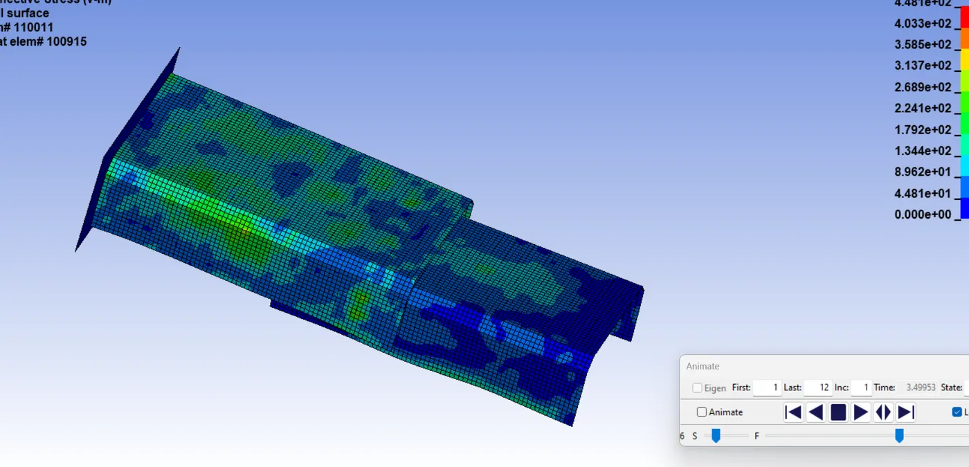
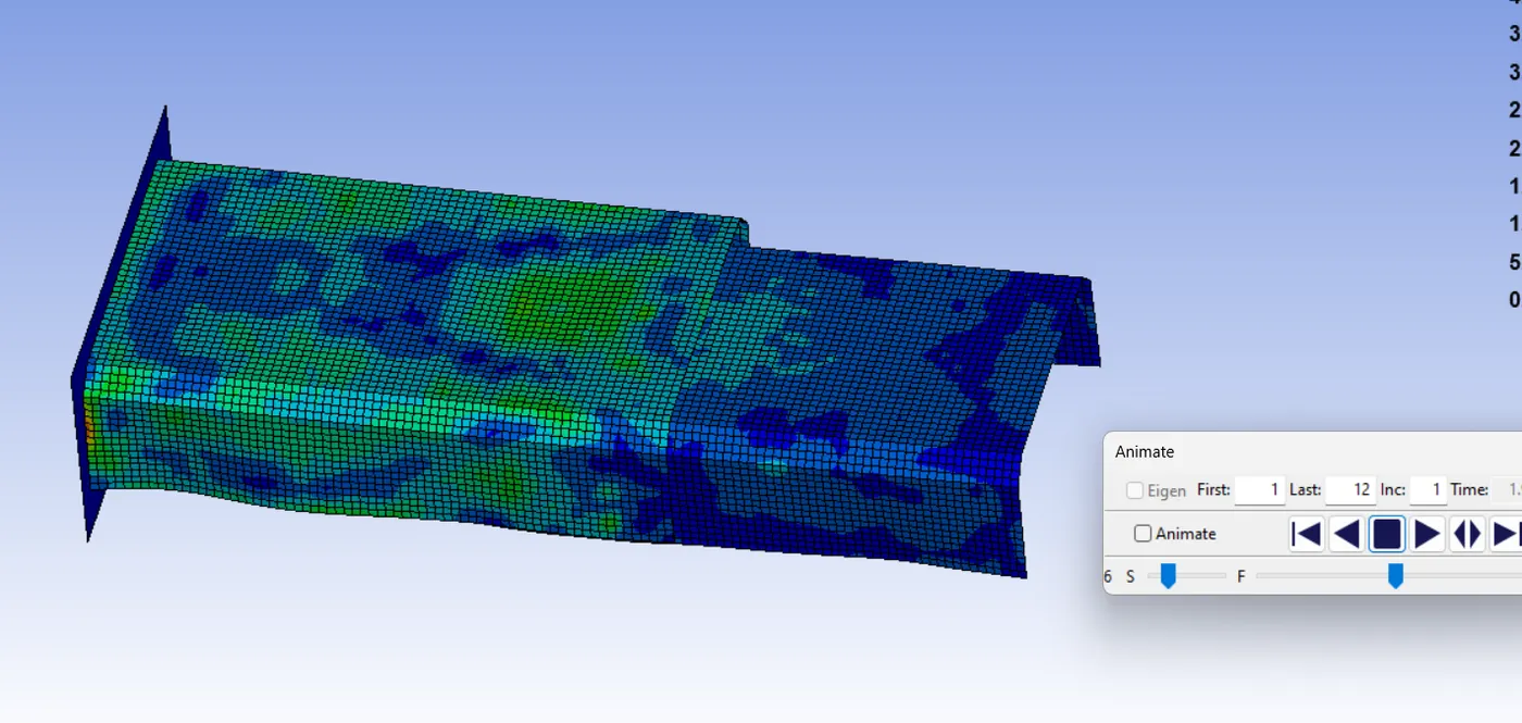
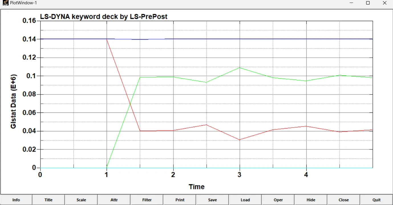
In both simulation the component hits the rigid wall at 1.0799 ms of the simulation. The spotweld fails exactly half the termination time. There is no abnormal behaviour of element during the simulation.
effective stress (v-m) beam spotweld
effective stress(v-m) solid spotweld
GLSTAT: GLOBAL ENERGIES PLOT.
beam spotweld
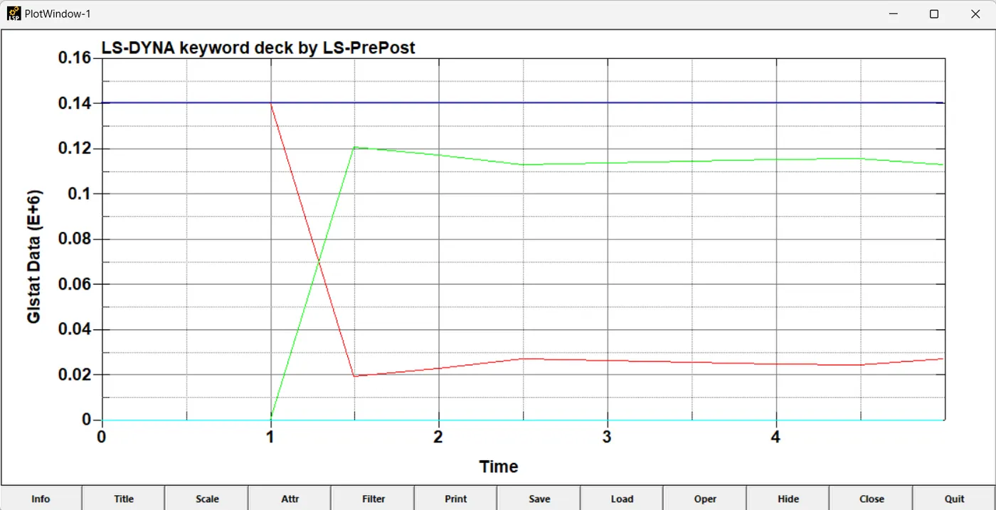
solid spotweld
------------------------------------Thank You------------------------------------------