Week - 5 - Modelling Spotwelds
AIM: To simulate the spotweld created using beam and solid element and run the model to compare them.
ABSTRACT: In this challenge, we will compare the models first by creating the spot weld using beam element and then by creating the element using the solid hexa element. after running we will also compare the post-processing results.
THEORY:
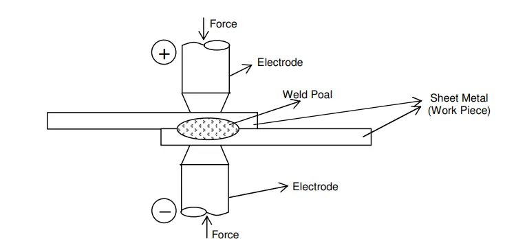
Spot welding is a type of resistance welding technique that comes under the fusion welding category where heat and pressure both are applied in order to join two parts. The Heat produced is due to the resistance of the current flow through the material air gap. The heat generated is equal to I2RI2R and nugget formation happens. Then when held for a few fractions of seconds the fusion between the part happens.
METHODOLOGY:
To run the simulation we need to follow certain steps
- Open the keyword file in the LS Pre-post environment.
- Create the beam element for spotweld.
- Define the Material card and section card for spotweld and as well as for the plate to be welded.
- Assign the section and material for the weld beam part and also for plates.
- Define the contact type between the plate and plot weld as well as for the plate self impact.
- Create the initial velocity card for the parts as 50kmph or 13.889 mm/ms.
- Create the planer rigid wall 20 mm way.
- Define the DATABASE cards such as D3PLOT, ASCII, NODE HISTORY, SWFORCE, ...etc.
- Define the control card Termination.
- Save as keyword then RUN the file to create the output file into the solver.
- Analyze the post-simulation results.
- Run the same by changing the welding element as solid(hexa) and a new section with the same material card.
PROCEDURE:
Open the keyword file in the LS Pre-post environment.
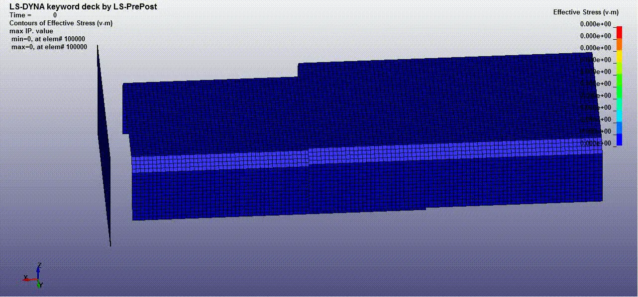
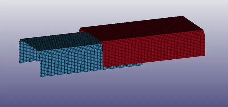
open the keyword file on ls pre-post to set the deck file. once we open the file we can see two plates that needed to be weld. using beam element and then using hexa solid element.
Create the beam element for spotweld.
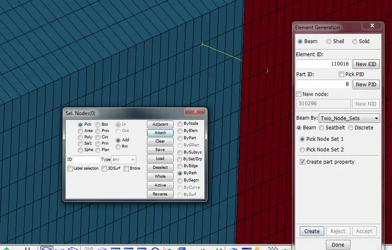
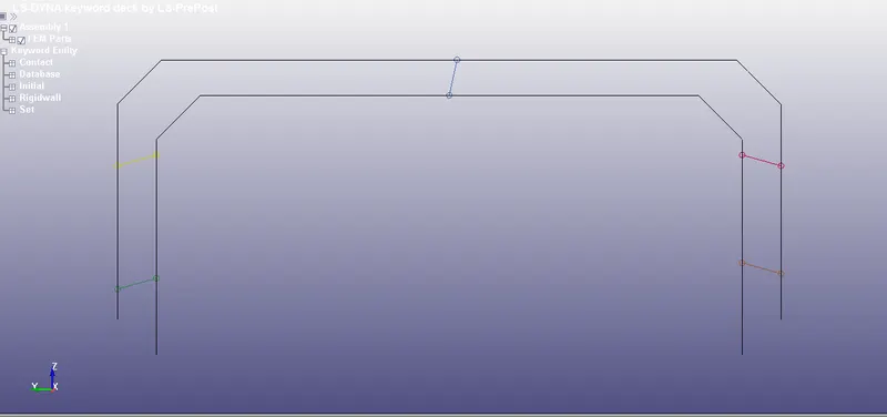
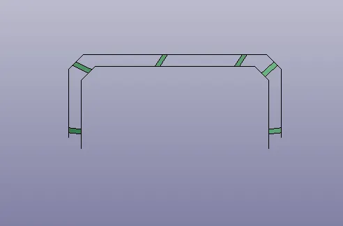
Create the beam element to represent the spot weld between two plates. to create that Goto element generation and under beam section and Beam By [Two_Node_set] pick the node-set 1 select the node and then pick node set 2 select the second node.
In a similar way create 5 sets of the beam elements. (As shown below).
Define the Material card and section card for spotweld and as well as for the plate to be welded.
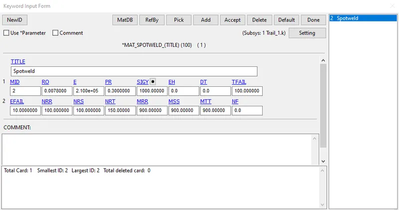
To define the material card for the spotweld select the MAT 100 give the steel properties. (gm, ms, mm)
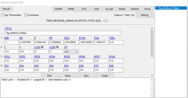
Define the material card for plates with a linear plastic card MAT24 using steel properties.
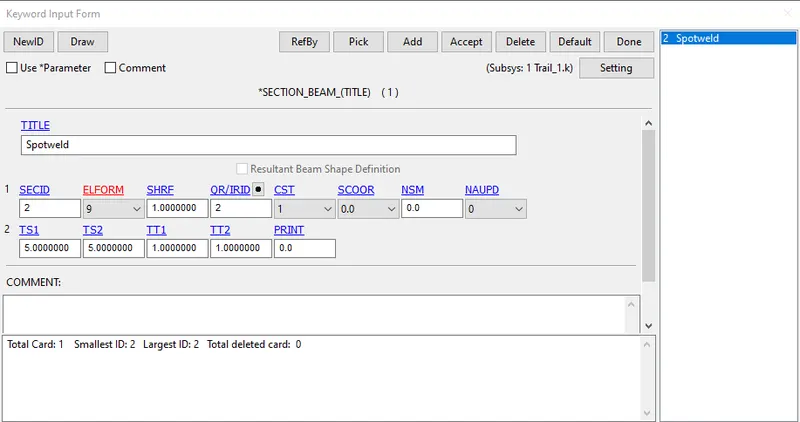
Define the section for the beam using SECTION_BEAM card with ELFORM 9 for spotweld.
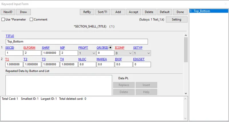
Define the section for the beam using SECTION_SHELL card with ELFORM 2 for spotweld.
Assign the section and material for the weld beam part and also for plates.
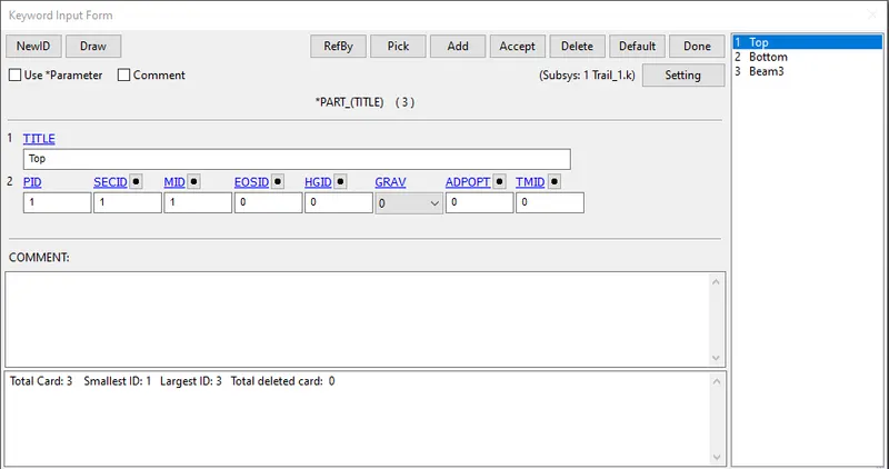
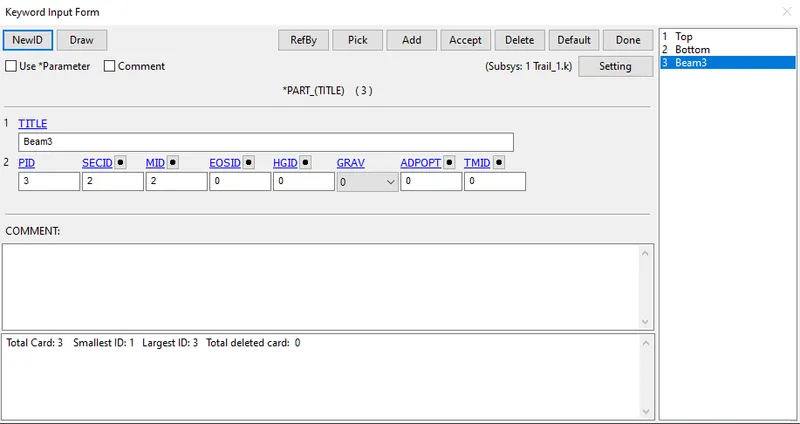
Create a part card for assigning for spot weld element material and section.
Define the contact type between the plate and plot weld as well as for the plate self impact.
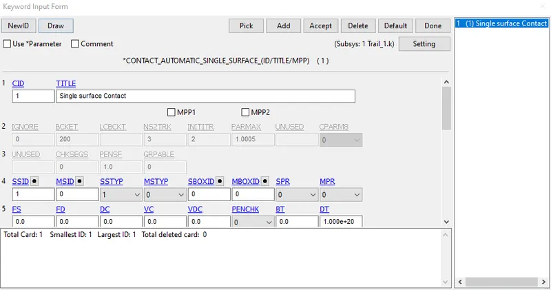
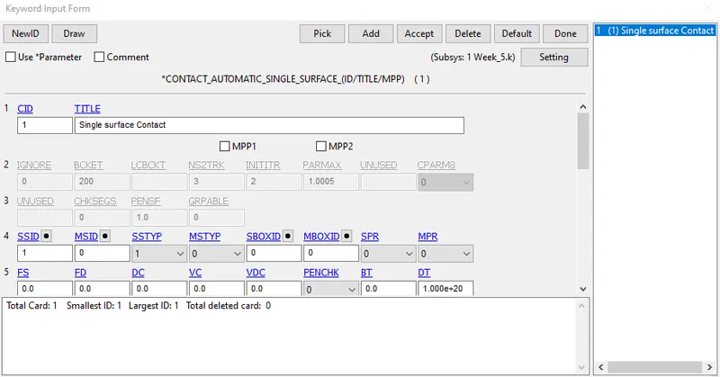
Define the contact card for spotweld and TIED_SHELL_EDGE_TO_SURFACE and AUTMOATIC_SINGLE_SURFACE for plate self Impact.
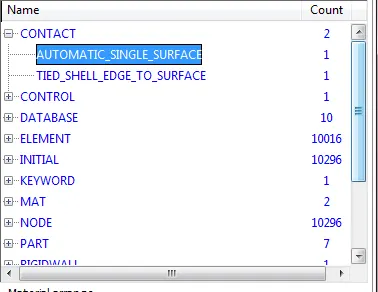
Set the plate under PART_SET and assign them as slave by selecting SSTYP as 2 & MSTYP as 0 for self contact.
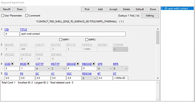
Set the node-set for beam and assign them as slave and master as plates using SSTYP as 4(node to the surface) and MSTYP as 2.
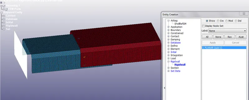
Create the planer rigid wall 20 mm way.
Create a rigid wall using create an entity and give a distance of 20mm from the part.
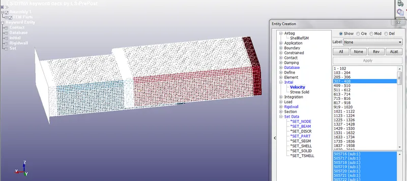
Create the initial velocity card for the parts as 50kmph or 13.889 mm/ms.
Create an initial velocity card using the create entity and assign 13.899 mm/ms speed to all components.
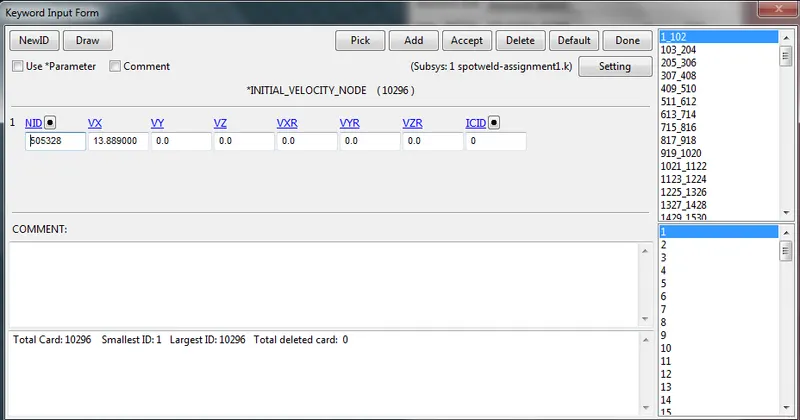
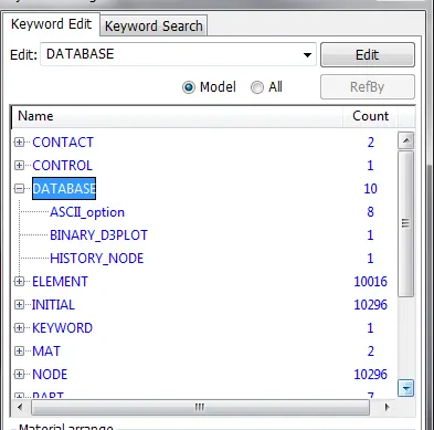
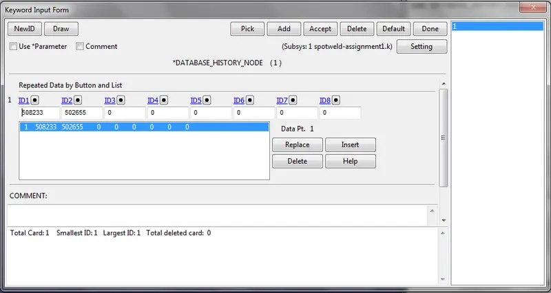
Define the DATABASE cards such as D3PLOT, ASCII, NODE HISTORY, SWFORCE, ...etc.
Define all the card necessary for viewing the result during post-processing such as BINARY_D3PLOT, ASCII_OPTION, HISTORY_NODE
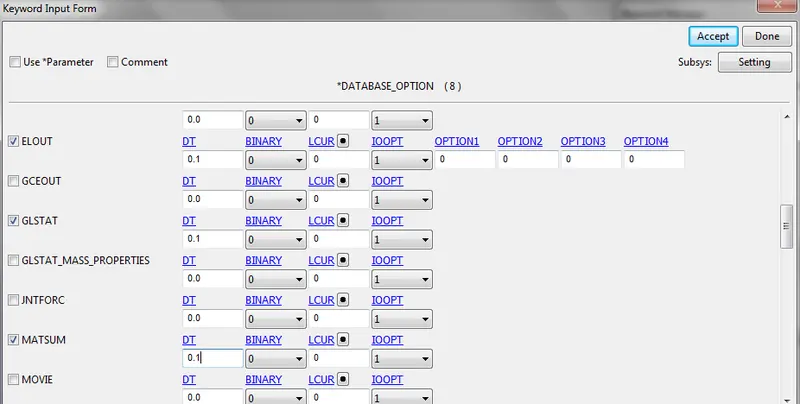
Check the ELOUT, GLSAT, MATSUM, SWFORC, NODEOUT with DT value as 0.1
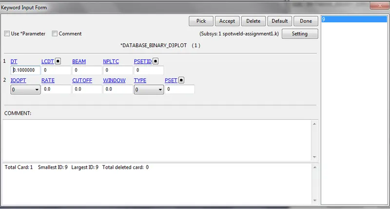
Also insert the node for which we need output data in HISTORY_NODE CARD
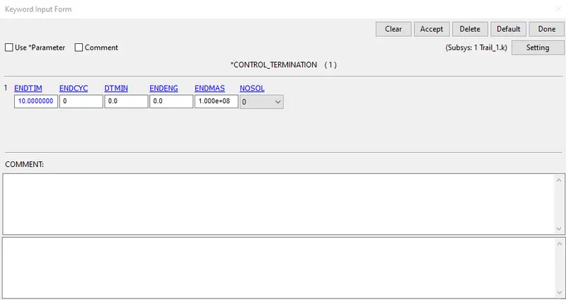
Define the control card Termination.
set the termination END TIME as 2 ms as similar to the previous challenge.
Case 2 For Hexa solid spotweld element
For case 2 for solid hexa spotweld element create the element using the element editing option and select 8 node points.
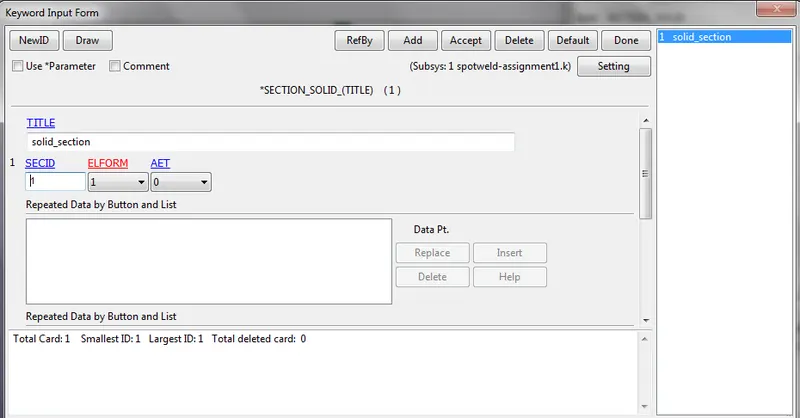
Use the Material card same as for steel created for beam element but change the Section card as SECTION_SOILDand ELFORM 1
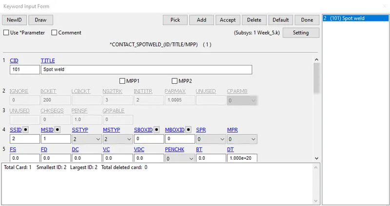
Define the contact type for Spotweld in solid element as CONTACT_SPOTWELD create as set of part and define spotweld as slave and plate as master.
CONCLUSION:
Axial and Shear Forces
Beam Element Case 1:
As we can see in the case of the beam element the axial force suddenly shoots up to the value of 0.8 E-12 at end of simulation but the shear force rises and 1.75 ms but then drops down.
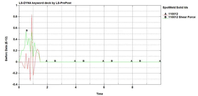
Solid Element (Hexa) Case 2
In the case of the solid element, the shear stress shoots up to a value of 0.85 E-12 at 1.5ms of simulation and stays at a constant value till the end of the simulation whereas the axial stress drops down.
Acceleration plot
Beam Element Case 1:
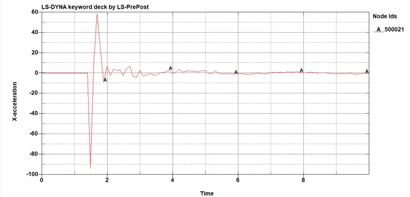
As we can see that for the beam element the acceleration of node 502655 drops at it deaccelerates after 1.4ms then reduces till the value of 100 mm/ms2 then settles down at the end of the simulation.
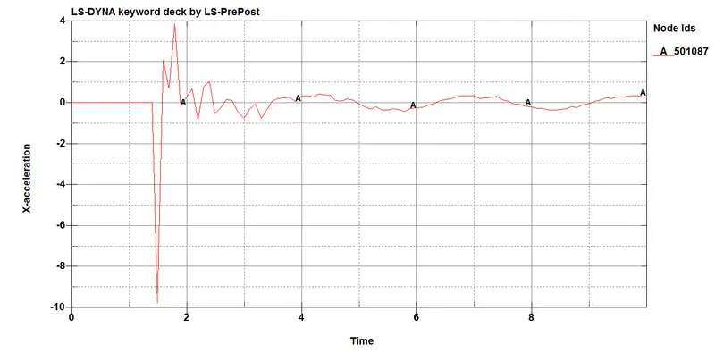
Solid Element (Hexa) Case 2
As we can see that for the soild element the acceleration of node 502655 drops at it accelerates after 1.5ms then reduces till the value of 200 mm/ms2 at 1.7 ms then settles down at the end of the simulation.
Energy plot
Beam Element Case 1:
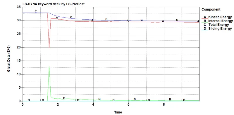
As we can see that the K.E is at a maximum at 33E+03 till 1.4 ms (impact time) then drops down and converts to internal energy (strain energy) and T.E is almost constant but a very small % is lost as sliding energy loss.
Solid Element (Hexa) Case 2
As we can see that the K.E is at a maximum at 32.5E+03 till 1.4 ms (impact time) then drops down and converts to internal energy (strain energy). hourglass energy is zero throughout the simulation and T.E is almost constant but a very small % is lost as sliding energy loss.
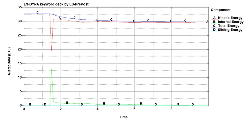
Energy plots are almost very similar for both the case but there is a difference in the K.E & I.E drops down in the center of the plots.
Effective stress plots
Beam Element Case 1:
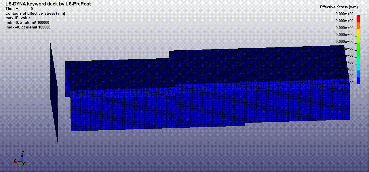
Animation
Solid Element (Hexa) Case 2