Week - 5 - Modelling Spotwelds
Crash Analysis of a Simple Assembly with Spot-Welds Using LS Dyna
by Swaroop Kumar Nagnoor
Problem Statement:
In this assignment, we have to model spotwelds for the given assembly of parts and run a crash test similar to the one in Assignment 4 (Crash-Box). Details about spotweld location is in the image below. The yellow line signifies the spotweld directions. We need to use 3-7 spotwelds along this line, in a symmetric manner, before running the simulation.
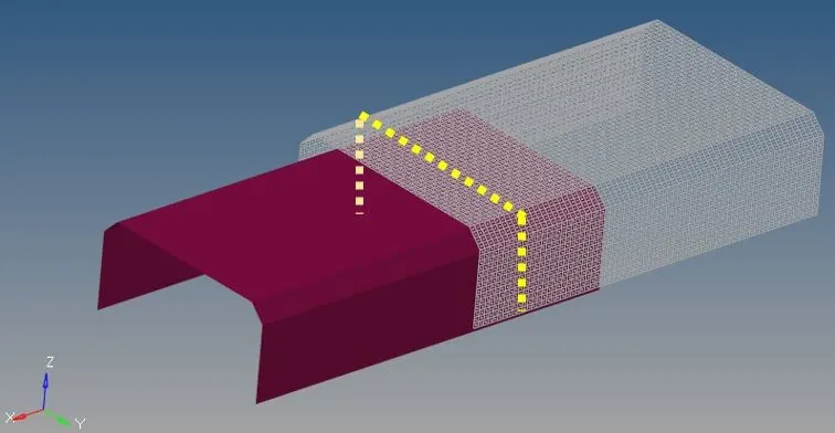
Figure 1: Spot-Weld location son the Assembly
An Input file containing the FE Model of Assembly of parts is provided. Crash Test Analysis has to be performed for the provided assembly by performing entire deck setup similar to that in Crash-Box analysis with additionally modelling the spot-welds. Analysis has to be performed by modelling the spot-welds with Beam elements in one case and with Solid elements in another.
Assumptions (as considered in the Crash-Box analysis):
- The assembly should crash into a rigid wall created using *RIGIDWALL keyword
- Material for the assembly is steel.
- The simulation needs to be started using elastic material to verify its correctness and later a nonlinear material card data will be provided.
- Thickness of the assembly is 2.0mm.
- Initial velocity for the assembly should be around 50 kmph
- The unit’s system to be used is gm-mm-ms
- The simulation should satisfy either of the two situations
- It crashes on the rigid wall and rebounces completely
- It buckles and folds in the axial direction so as to come in self-contact
Deliverables:
- Input and output files (. k, d3plot, glstat, sleout, rcforc)
- Animation of the final simulation
- Acceleration plot of a node in the middle of the assembly (preferably at the location of spot-weld)
- Plot of all energies (total, internal, kinetic, hourglass)
- Force plots on welds (swforc)
Spot-Weld Modelling in LS Dyna:
In LS Dyna, spot-welds can be modelled in the following ways,
- Using Beam element and Tied contact
- Using Constraint spotweld
- Using Constrained generalized
- Using Solid element and Spotweld contact.
In this analysis, we will use the Beam and Solid element approach to define our Spot-Welds
Aim:
To perform Crash Test for a simple assembly of parts with spot-welds using LS Dyna
Objectives:
- Creation of wall using *RIGIDWALL keyword
- Spot-weld modelling using Beam element and Solid element
- Complete deck setup using *INITIAL_VELOCITY card and other appropriate keywords and controls in LS-PrePost
- Analysis using LS-DYNA Analysis
- Post-processing of results using LS-PrePost
Deck Setup (Beam elements with Tied Contact):
- Import the FE Model from the provided Input file
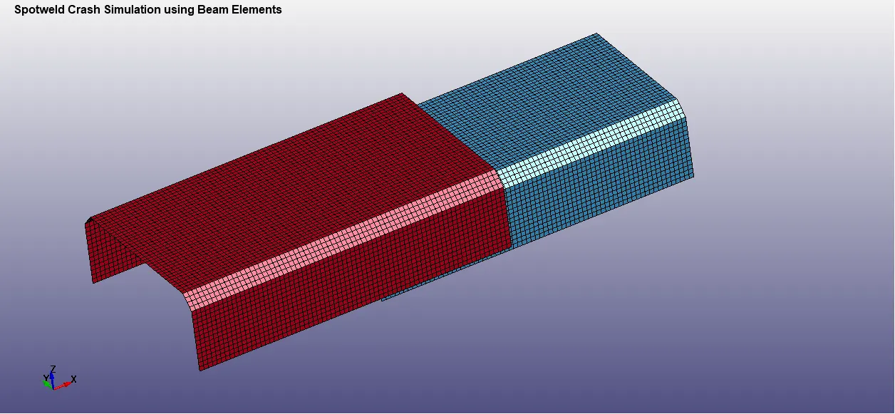
Figure 2: FE Model Input from keyword file
- Similar to the Crash-Box Analysis, create the following
- Wall using *RIGIDWALL keyword
- MAT-024-PIECEWISE_LINEAR_PLASTICITY for assembly
- *SECTION_SHELL with 2.0mm thickness for Assembly parts
- *INITIAL_VELOCITY loading for Assembly part
- Automatic Single Surface Contact for Assembly parts
- Create spot welds at the appropriate locations symmetrically using beam elements from the element and mesh utility tab
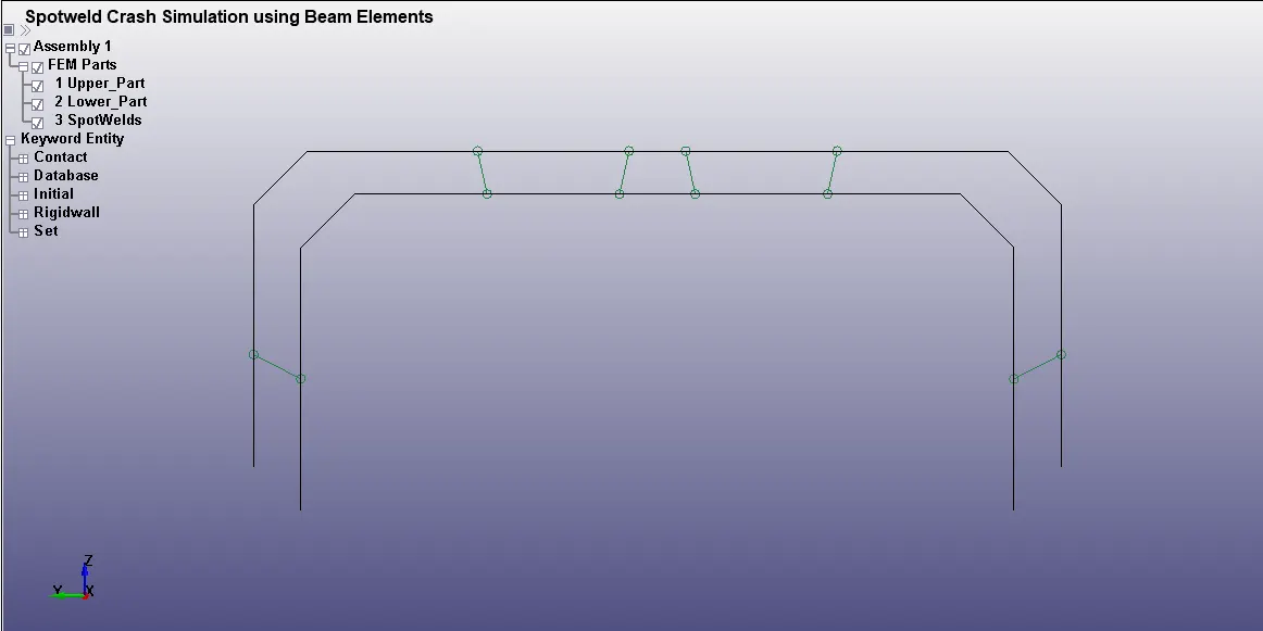
Figure 3: Spot-Welds modeled with Beam elements
*SECTION_BEAM for defining the beam cross-section (use tubular section as rectangular type gives zero cross-section area during the simulation) with element formulation (ELFORM = 9) as the other type of element formulation does not support MAT_SPOTWELD
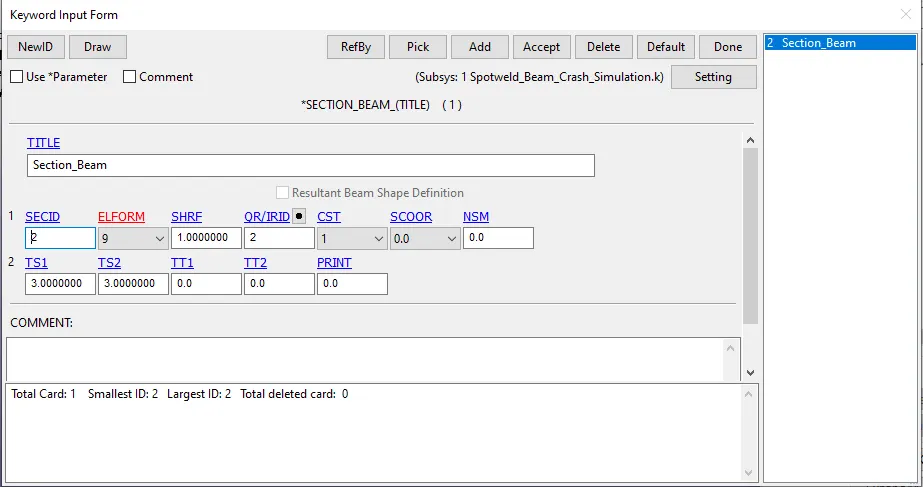
Figure 4: SECTION_BEAM for spot-welds with Beam elements
- Since the failure of the Spot-Welds has to be analysed, time for failure (TFAIL) is assumed to be at 0.6ms
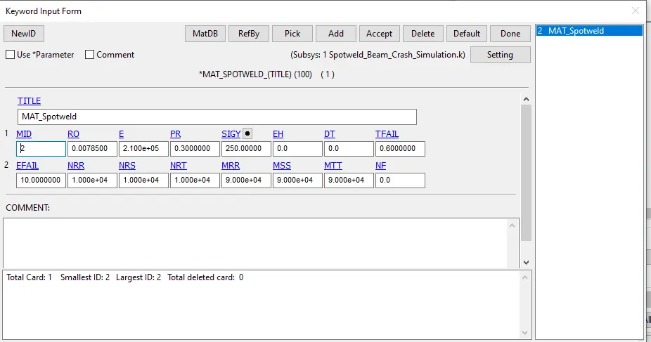
Figure 5: MAT_SPOTWELD for Spot-welds with Beam elements
- The Spot-Welds with Beam elements use TIED CONTACTS as per the definition in LS Dyna
- All the spot welds are assigned as slave and the part set containing the assembly parts are assigned as Master
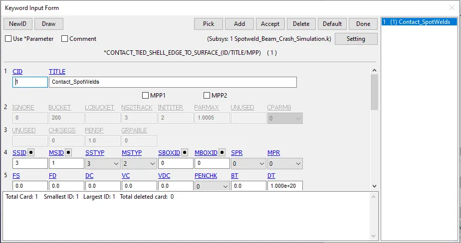
Figure 6: TIED-CONTACT definition for Beam elements
- Node set of one of the Beam elements representing the Spot-Weld is considered for extracting the Nodal accelerations
- Control_Termination is defined with a total run time of 1ms, where the box is assumed to touch the rigid wall within 0.4 ms with the prescribed velocity.
- Control_Hourglass and Control_Energy are defined with default values
- A time step (dt) of 0.005 ms is defined for saving the output files and the same is included in the BINARY_D3PLOT and ASCII_Option for GLSTAT, MATSUM, NODOUT, RCFORC, SLEOUT and SWFORC
Deck Setup (Solid elements with Contact Spotweld):
- The Beam Elements which represent the Spot-welds are replaced by Solid Hexa elements with SECTION_SOLID and ELFORM = 1, and the contact type is changed to CONTACT_SPOTWELD. The material of the spot-weld is kept same as that of the Beam elements
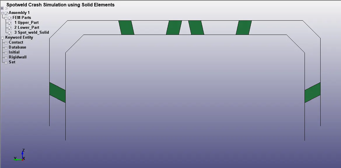
Figure 7: Spot-Welds modeled with Solid elements
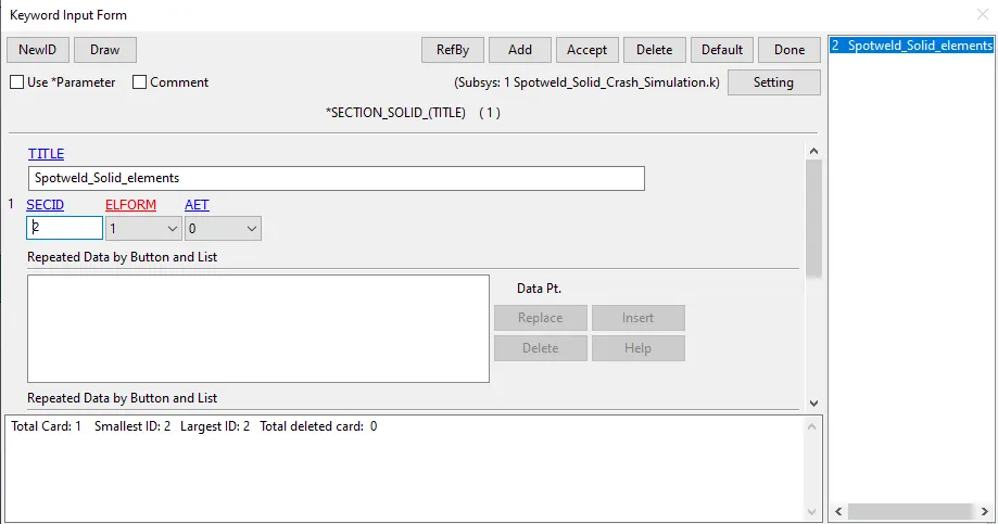
Figure 8: SECTION_SOLID for spot-welds with Solid elements
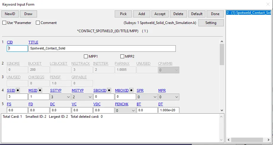
Figure 9: CONTACT_SPOTWELD definition for Solid elements
Analysis:
- The failing of the Spot-Weld modeled with Beam elements occurs at 0.6ms as defined in the MAT entry
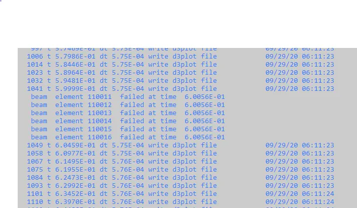
Figure 10: Spot-Weld fail time: Beam Element
- The failing of the Spot-Weld modeled with Solid elements occurs at 0.6 ms as defined in the MAT entry
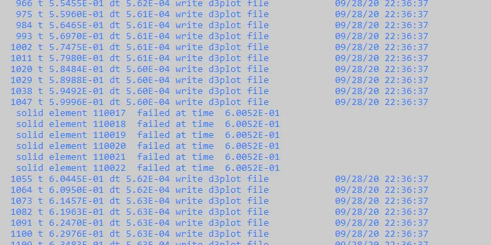
Figure 11: Spot-Weld fail time: Solid Element
Results:
Energy Plots:
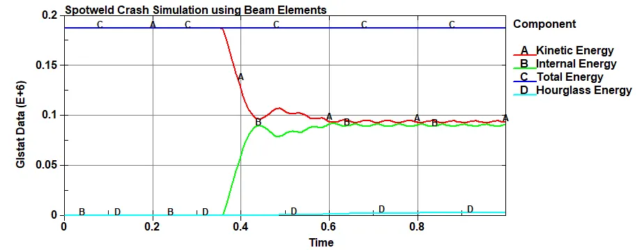
Figure 12: Plots of Kinetic Energy, Internal Energy, Total Energy and Hourglass Energy for Crash Simulation defined by Beam Element Spot-welds
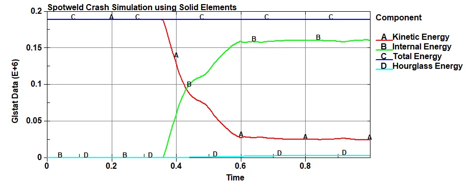
Figure 13: Plots of Kinetic Energy, Internal Energy, Total Energy and Hourglass Energy for Crash Simulation defined by Solid Element Spot-welds
- Observations:
- Reduction in Kinetic energy and Increase in Internal Energy is more for Solid Elements Spot-weld model as compared to Beam Elements model
- Total Energy remains same for both the cases
Nodal Accelerations (X-direction):
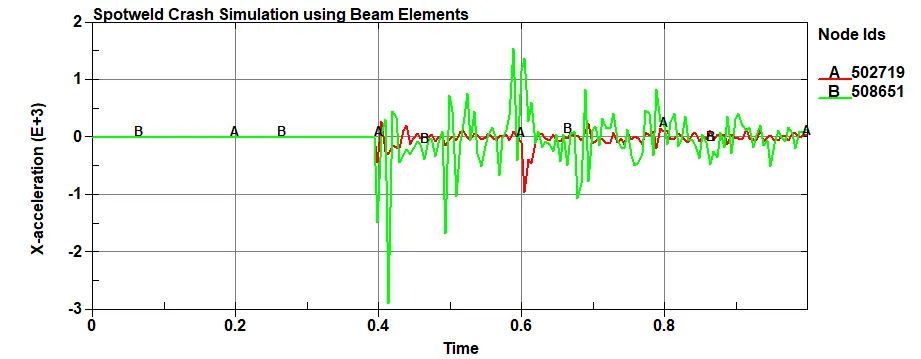
Figure 14: Nodal accelerations in X-direction for Crash Simulation defined by Beam Element Spot-welds
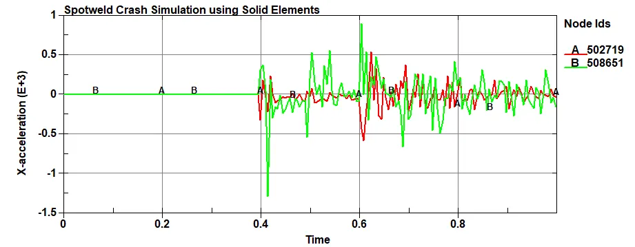
Figure 15: Nodal accelerations in X-direction for Crash Simulation defined by Solid Element Spot-welds
- Observations:
- Since the bottom part of the assembly is the first to hit the wall, the acceleration of bottom part (represented by Node: 508651) is more than the top part of the assembly (represented by Node: 502719)
- The magnitude of the accelerations generated by model with Beam elements is more than that represented by Solid elements
Spot-Welds Force Plots
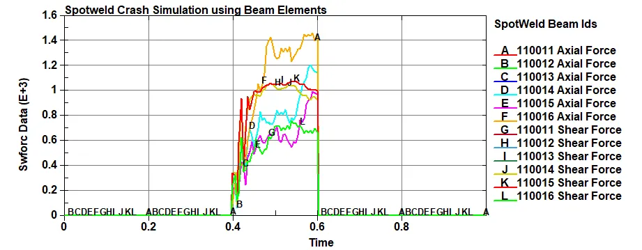
Figure 16: Axial and Shear force on spot-welds: Beam Elements
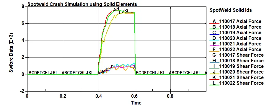
Figure 17: Axial and Shear force on spot-welds: Solid Elements
- Observations:
- Similar values of axial forces and shear forces can be seen for spot welds modelled by 1D beam element and the force values drop to zero after the spot weld fails.
- Higher shear forces are notices comparatively to axial forces for spot welds modelled by solid element. This is because of the good force resisting ability of solid element in the transverse direction.
Spot-Welds Failure Plots
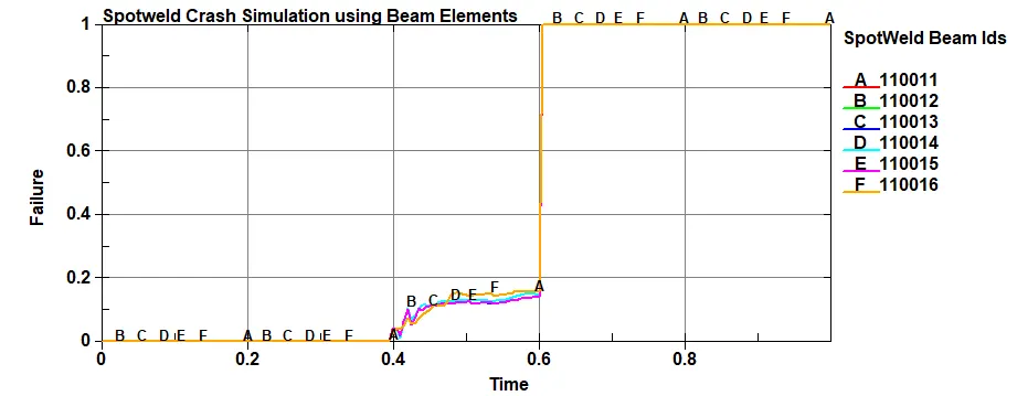
Figure 18: Spot-welds Failure: Beam Elements
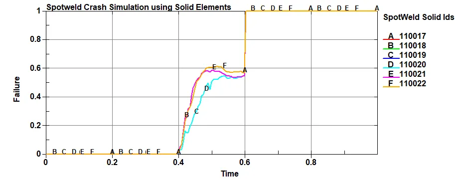
Figure 19: Spot-welds Failure: Solid Elements
- Observations:
- After the impact, Spot-Welds modeled with Solid elements tend to fail faster than the Spot-Welds modeled with Beam elements
Conclusion:
Crash Analysis for a Simple Assembly with Spot-Welds modeled by Beam elements and Solid elements is performed and the results for both are compared and documented.