Week - 4 - crash box simulation
Crash Test Analysis of a Crash Box Using LS Dyna
by Swaroop Kumar Nagnoor
Problem Statement:
A crash box is a highly energy absorbing structure that crashes on application of loads and reduces impact on other components nearby. A full-fledges crash box is a highly sophisticated design but, in this case, we will go with a rectangular channel which can thought of as the most simple Crash Box.
An Input file containing the FE Model of Rectangular Crash Box is supplied. Crash Test Analysis has to be performed for the provided Crash Box model by performing entire deck setup and analysis along with postprocessing of the results for two different thickness of Crash Box (1.2 mm and 1.5 mm).
Assumptions and Additional Information for the Problem:
- The crash box should crash into a rigid wall created using *RIGIDWALL keyword (Check the manual to understand and create a rigid wall)
- Material for the crash box is steel.
- The simulation needs to be started using elastic material to verify its correctness and later a nonlinear material card data will be provided.
- Thickness of the crash box is 1.2mm.
- Initial velocity for the crash box should be around 50 kmph
- The unit’s system to be used is gm-mm-ms
- The simulation should satisfy either of the two situations
- It crashes on the rigid wall and rebounces completely
- It buckles and folds in the axial direction so as to come in self-contact
Deliverables:
- Input and output files (. k, d3plot, glstat, sleout, rcforc)
- Animation of the final simulation
- Cross-sectional force generated in the middle of the crash box (along its length)
- Acceleration plot of a node in the middle of the crash box (along its length)
- Maximum directional stress and strain along the length of the crash box (X strain, Y strain etc)
- Plot of all energies (total, internal, kinetic, hourglass, sliding)
- Compare the accelerations and stress/strain plots of 1.2mm and 1.5mm crash boxes.
Aim:
To perform Crash Test for a simple rectangular crash box model using LS Dyna
Objectives:
- Creation of wall using *RIGIDWALL keyword
- Complete deck setup using *INITIAL_VELOCITY card and other appropriate keywords and controls in LS-PrePost
- Analysis using LS-DYNA Analysis
- Post-processing of results using LS-PrePost
Deck Setup (1.2mm thickness):
- Import the FE Model from the provided Input file
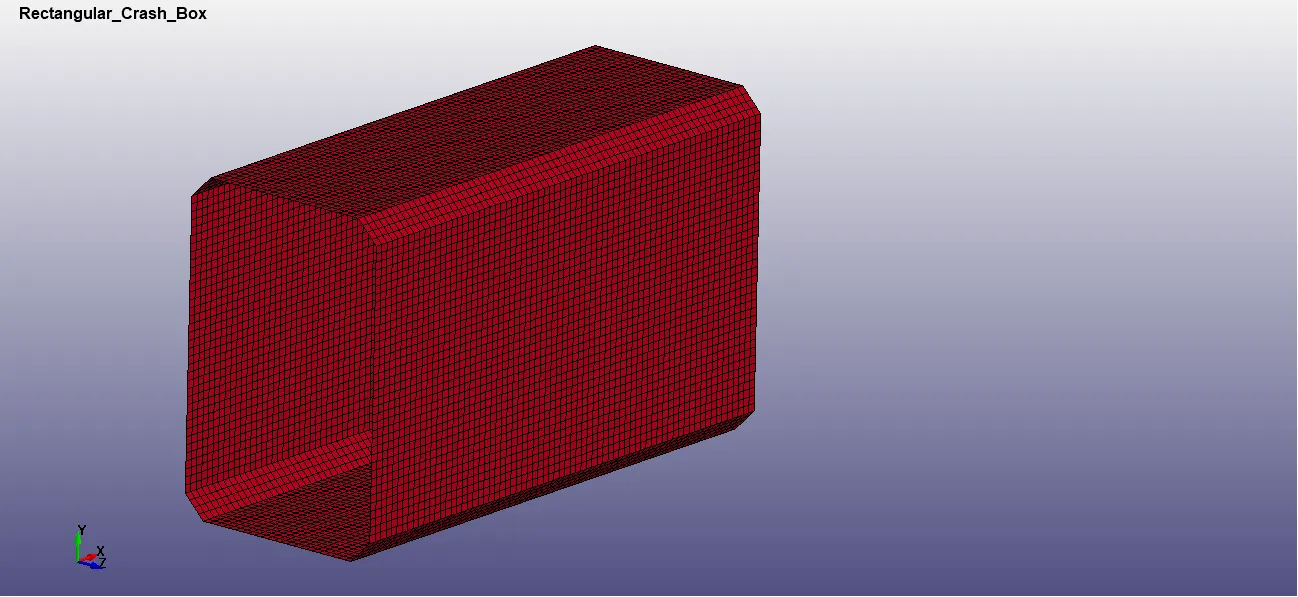
Figure 1: FE Model Input from keyword file
- Create a Wall using *RIGIDWALL keyword from the Create Entity option and use the base nodes of the box to define the plane of the wall
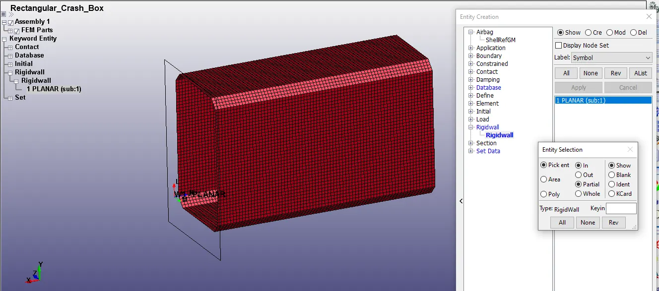
Figure 2: Rigid wall creation
- The normal of the wall has to be pointed towards the crash box
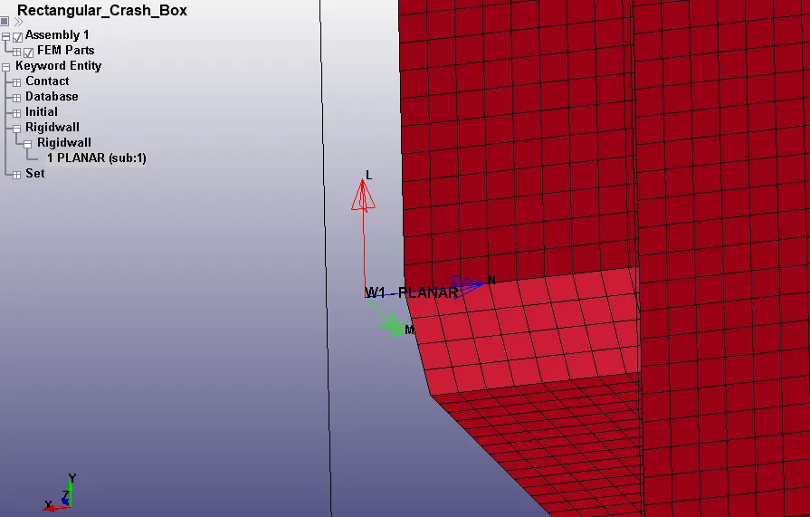
Figure 3: Rigid wall Normal direction
- Since the material experiences plastic strains, 024-PIECEWISE_LINEAR_PLASTICITY material is considered with
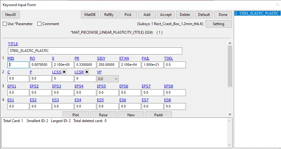
Figure 4: Material Card for Crash Box
- Since all the elements in the current analysis are Shell, a *SECTION_SHELL card is defined with a thickness value of 1.2mm
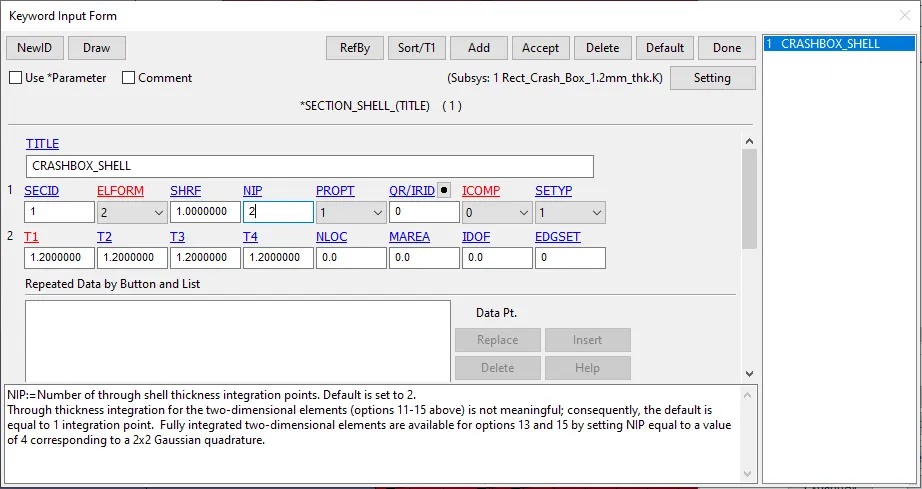
Figure 5: Shell Section Definition
- Once the material type and the section type are defined, we have to update the same properties to the parts containing those elements
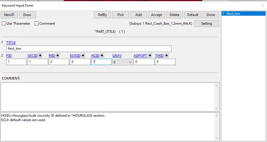
Figure 6: Properties updation for Rectangular Box
- All the nodes of the rectangular box are expected to be travelling with the same velocity and hence a NODE_SET is created for these nodes and the *INITIAL_VELOCITY loading is then assigned.
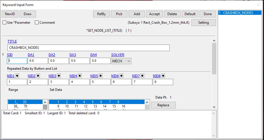
Figure 7: Node Set for Rectangular Box
- The Rectangular Box is travelling at a velocity of 50KMPH as defined in the problem statement. Converting that into the unit system as that of the model gives a velocity of 13.89 mm/ms
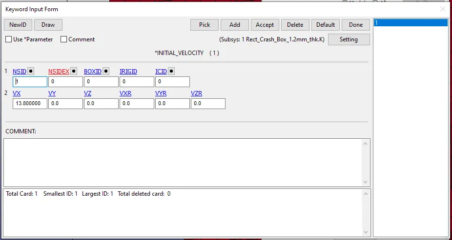
Figure 8: Defining INITIAL VELOCITY for Rectangular Box
- The rectangular box is either assumed to bounce back after hitting the rigid wall or is expected to buckle and fold onto itself thereby coming in self-contact with itself. For this reason, Automatic Single Surface Contact is defined for the box which itself acts a slave without any requirement for a master.
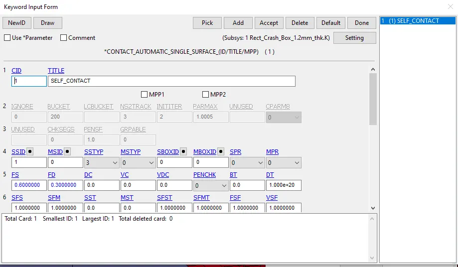
Figure 9: Contact Definition (Automatic Single Surface)
- Since the forces at the middle of the cross-section along the length of the box are required as output, a plane is defined at that location and a database card (Cross-section) is created for extracting the required forces
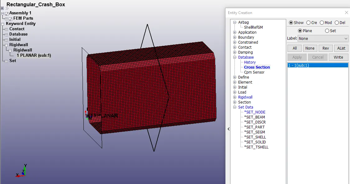
Figure 10: Cross section forces definition
- In a similar fashion, a middle node (Node ID: 5041) is defined for extracting acceleration plot
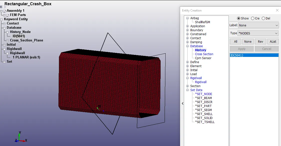
Figure 11: Node for Acceleration plot in Middle of Box
- Control_Termination is defined with a total run time of 1ms, where the box is assumed to touch the rigid wall within 0.4 ms with the prescribed velocity.
- Control_Hourglass and Control_Energy are defined with default values
- A time step (dt) of 0.005 ms is defined for saving the output files and the same is included in the BINARY_D3PLOT and ASCII_Option for GLSTAT, MATSUM, RCFORC and SLEOUT
Deck Setup (1.5mm thickness):
- Once the deck setup for the 1.2mm thickness Crash box of complete, the keyword file is edited in notepad++ and the value of thickness in the *SECTION_SHELL are changed from 1.2 to 1.5 in all the four tabs and the file is saved with a new name
- This completes the deck setup for 1.5mm thickness Crash Box
Results:
1.2mm thickness Crash Box
- Energy Plots:
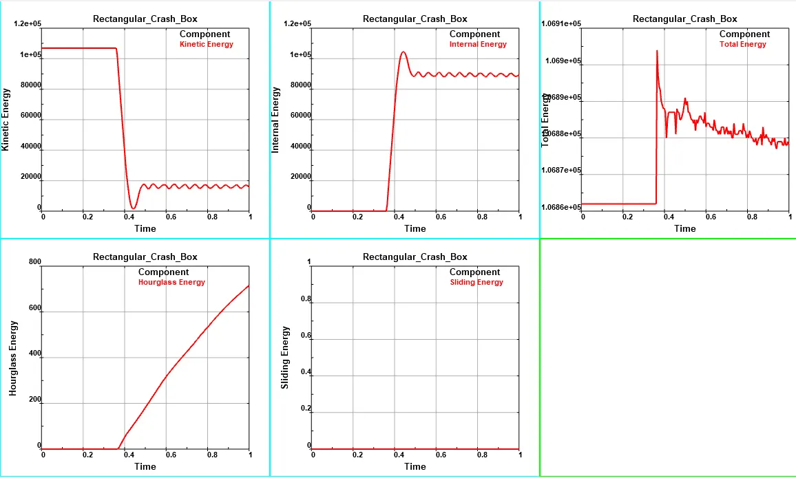
Figure 12: Plots of Kinetic Energy, Internal Energy, Total Energy, Hourglass Energy and Sliding Energy for Box Thickness = 1.2mm
- Cross-sectional Forces generated at middle of Crash Box:
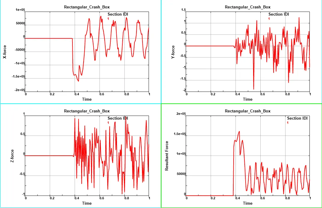
Figure 13: Cross-sectional forces (X, Y Z & Resultant) at middle of Crash Box for Box Thickness = 1.2mm
- Acceleration of Middle Node:
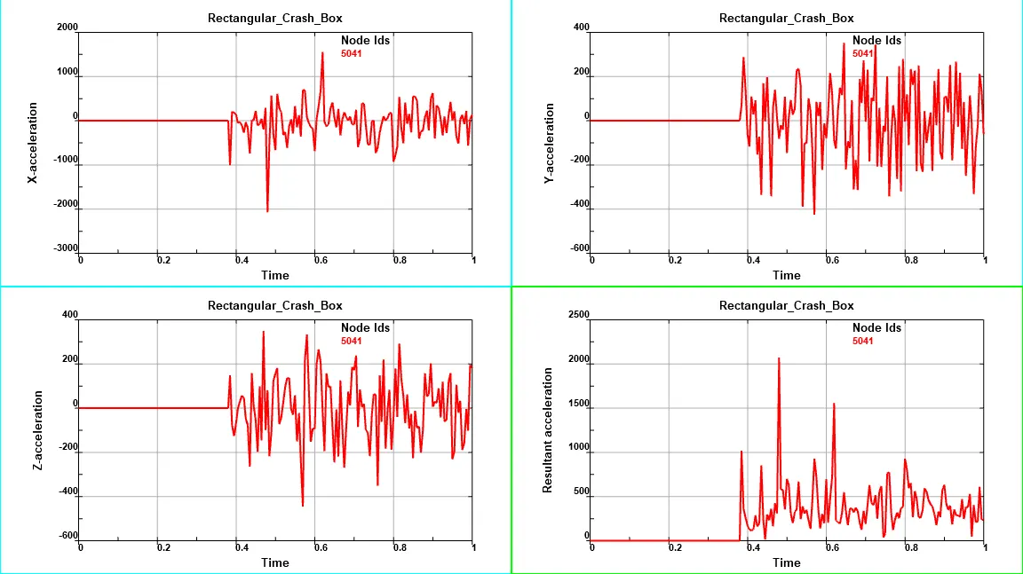
Figure 14: Acceleration of Node (X, Y Z & Resultant) at middle of Crash Box for Box Thickness = 1.2mm
- Contour of Maximum Effective Stress (vonMises):
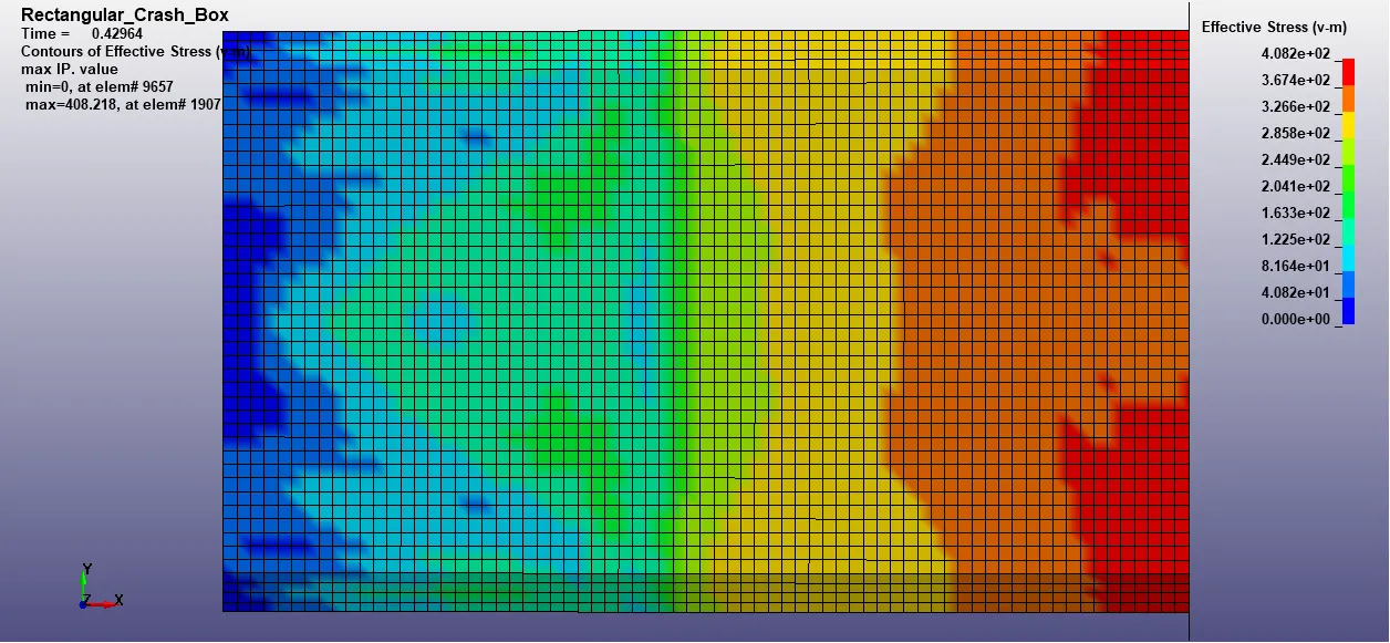
Figure 15: Contour of Maximum Effective vonMises Stress on Crash Box for Box Thickness = 1.2mm
- Stress variation plot for Element (1907) having maximum value of Effective vonMises Stress
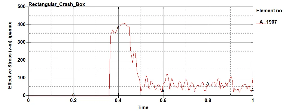
Figure 16: Effective vonMises Stress variation plot for Element (1907) on Crash Box for Box Thickness = 1.2mm
- Contour of Effective Plastic Strain @ Maximum Effective vonMises Stress:
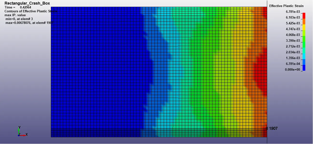
Figure 17: Contour of Effective Plastic Strain @ Maximum Effective vonMises Stress on Crash Box for Box Thickness = 1.2mm
- Effective Plastic Strain variation plot for Element (1907) having maximum value of Effective vonMises Stress
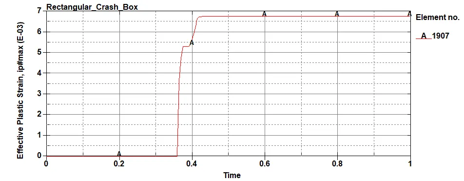
Figure 18: Effective Plastic Strain variation plot for Element (1907) on Crash Box for Box Thickness = 1.2mm
- From the above graphs and contours following observations are made for box thickness = 1.2mm:
- Sliding Energy of the box is zero as the box does not buckle to itself and hence no contact is active
- From the cross-sectional forces, the major contribution to the resultant force is the X-component of force as the box is moving in X-direction only
- Since the box is moving with a constant velocity, there is no acceleration until it hits the rigid wall. Thereafter, since the box is bouncing back, acceleration is observed in all the three components and hence the resultant component of acceleration is positive
- Maximum Effective vonMises Stress on the box is observed at a time step of 0.429 ms, when the box has completely hit the wall. The magnitude of the stress (409 MPa) is more than the yield limit of the material (250 MPa) and hence it shows that the material is now in plastic region of the stress-strain curve
- Effective Strain on the element at Maximum Effective vonMises Stress is observed to be more than 0.6% which is more than the allowable plasticity limit of the material (0.5%)
1.5mm thickness Crash Box
- Energy Plots:
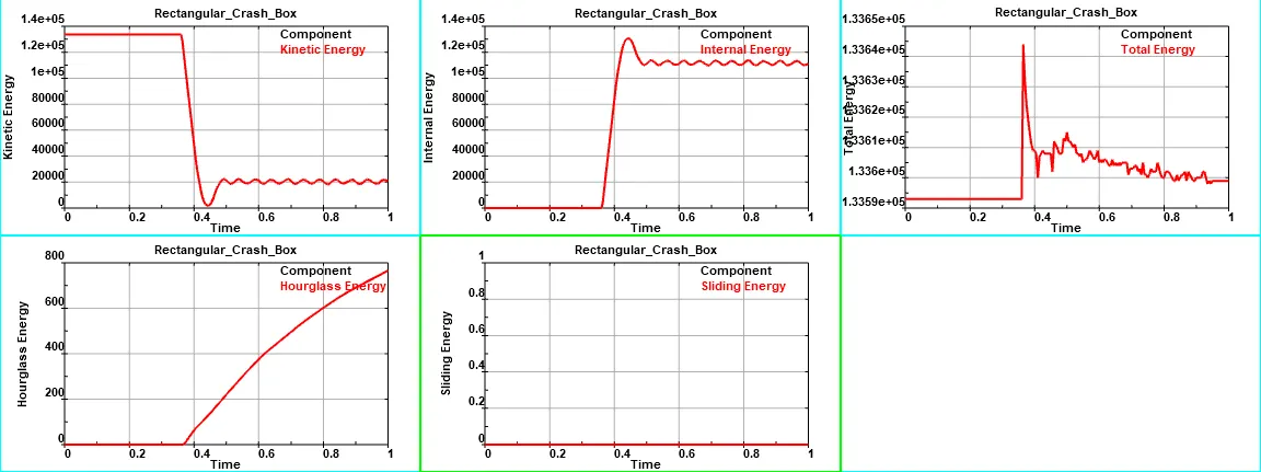
Figure 19: Plots of Kinetic Energy, Internal Energy, Total Energy, Hourglass Energy and Sliding Energy for Box Thickness = 1.5mm
- Cross-sectional Forces generated at middle of Crash Box:
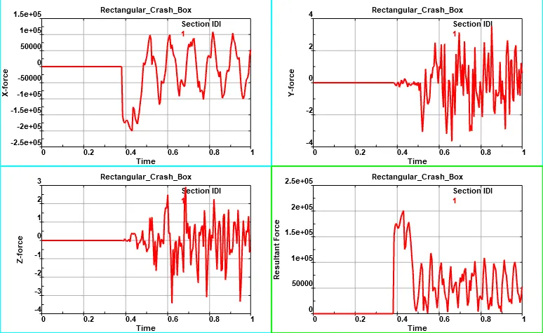
Figure 20: Cross-sectional forces (X, Y Z & Resultant) at middle of Crash Box for Box Thickness = 1.5mm
- Acceleration of Middle Node:
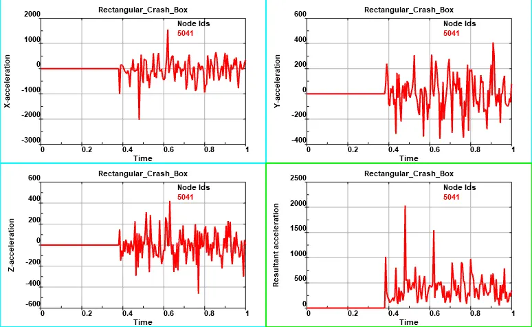
Figure 21: Acceleration of Node (X, Y Z & Resultant) at middle of Crash Box for Box Thickness = 1.5mm
- Contour of Maximum Effective Stress (vonMises):
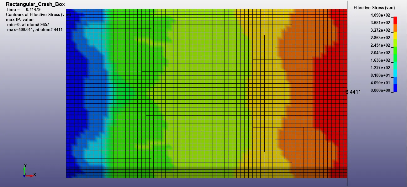
Figure 22: Contour of Maximum Effective vonMises Stress on Crash Box for Box Thickness = 1.5mm
- Stress variation plot for Element (4411) having maximum value of Effective vonMises Stress
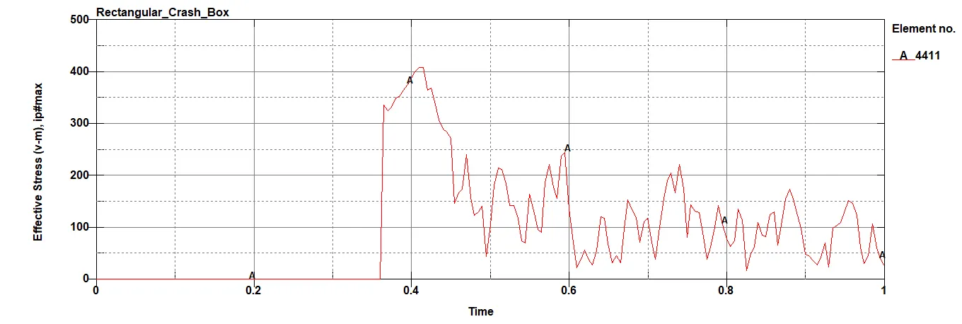
Figure 23: Effective vonMises Stress variation plot for Element (4411) on Crash Box for Box Thickness = 1.5mm
- Contour of Effective Plastic Strain @ Maximum Effective vonMises Stress:
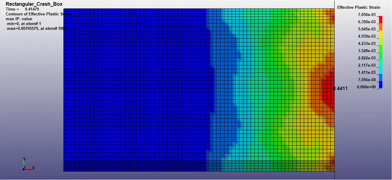
Figure 24: Contour of Effective Plastic Strain @ Maximum Effective vonMises Stress on Crash Box for Box Thickness = 1.5mm
- Effective Plastic Strain variation plot for Element (4411) having maximum value of Effective vonMises Stress
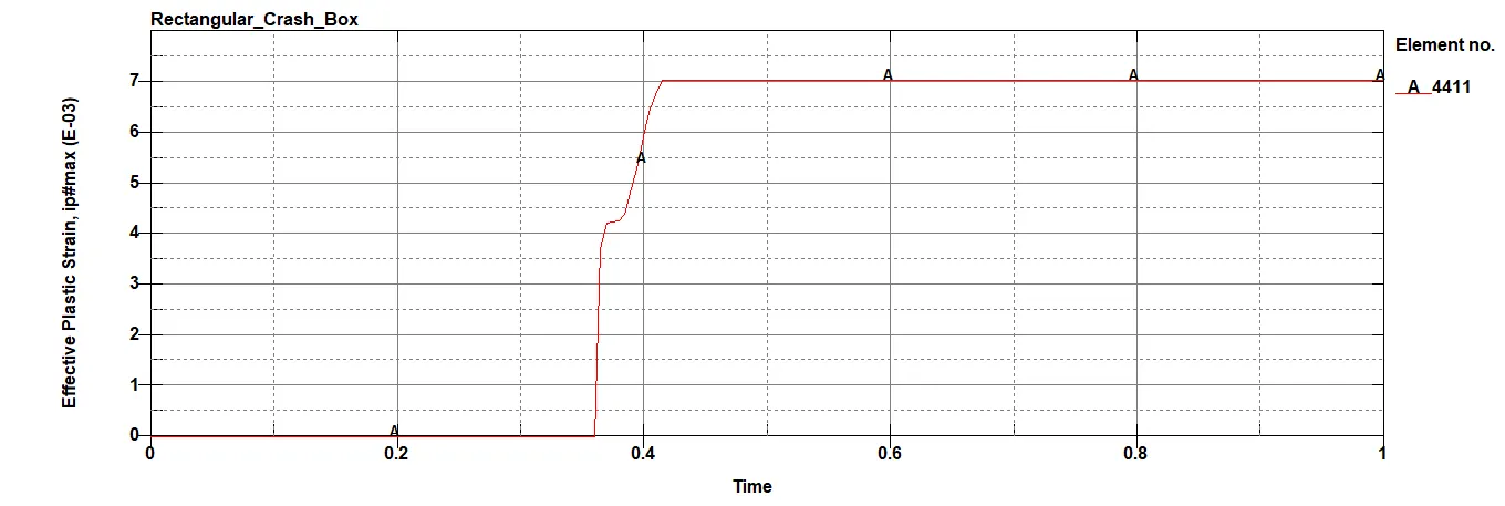
Figure 25: Effective Plastic Strain variation plot for Element (4411) on Crash Box for Box Thickness = 1.5mm
- From the above graphs and contours following observations are made for box thickness = 1.5mm:
- Sliding Energy of the box is zero as the box does not buckle to itself and hence no contact is active
- From the cross-sectional forces, the major contribution to the resultant force is the X-component of force as the box is moving in X-direction only
- Since the box is moving with a constant velocity, there is no acceleration until it hits the rigid wall. Thereafter, since the box is bouncing back, acceleration is observed in all the three components and hence the resultant component of acceleration is positive
- Maximum Effective vonMises Stress on the box is observed at a time step of 0.414 ms, when the box has completely hit the wall. The magnitude of the stress (409 MPa) is more than the yield limit of the material (250 MPa) and hence it shows that the material is now in plastic region of the stress-strain curve
- Effective Strain on the element at Maximum Effective vonMises Stress is observed to be more than 0.7% which is more than the allowable plasticity limit of the material (0.5%)
Conclusion:
Crash Analysis for a Simple Rectangular Crash Box is performed for two values of thickness (1.2mm and 1.5mm) and the results are plotted. Stresses and Strains are exceeding the allowable limits in both the cases.
The objective of the analysis is hence accomplished and the same is documented.