Week - 5 - Modelling Spotwelds
Week 5 - Modelling Spotwelds
Aim:
To model a Spot weld using beam and solid elements and to compare the test results for the beam and solid elements. And also, to perform a crash analysis.
Explanation:
-Spot welds are usually done on sheet metal for joining two parts together.
- Spot welds can be modeled in 4 ways using LS-dyna.
Beam elements
-Tied contacts
-Constrained spot weld
-Generalized constrained spot weld
Solid Elements
-Solid Hex
-Contact spot weld
Procedure:
Common procedure
Step 1:
Open the LS- Dyna program manager > start LS prepost > Open the keyword file
Step 2:
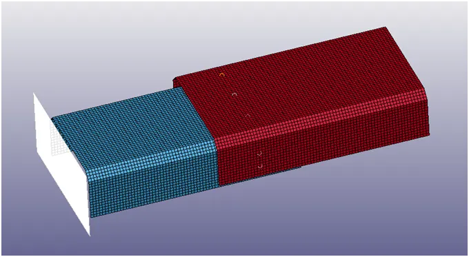
Create a Rigid wall and input the Initial velocity as 14mm/ms along (+ve) x direction.
For Beam Spot weld
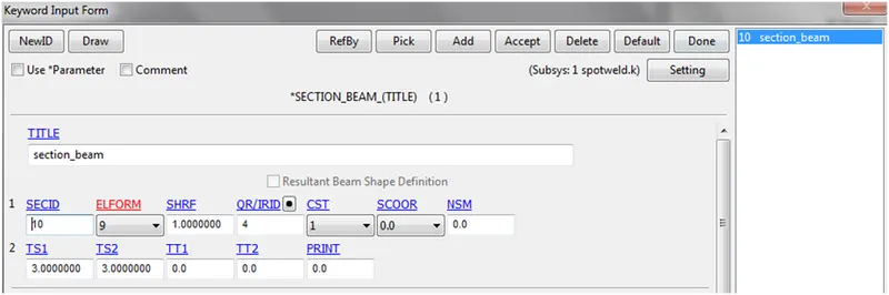
- Create Section Beam with element formulation (ELFORM 9).
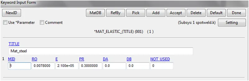
- Create material card (MAT 01 elastic) for the sheet metal parts and (MAT 100 Spot weld) for the spot weld.
(MAT 01 elastic)
(MAT 100 Spot weld)
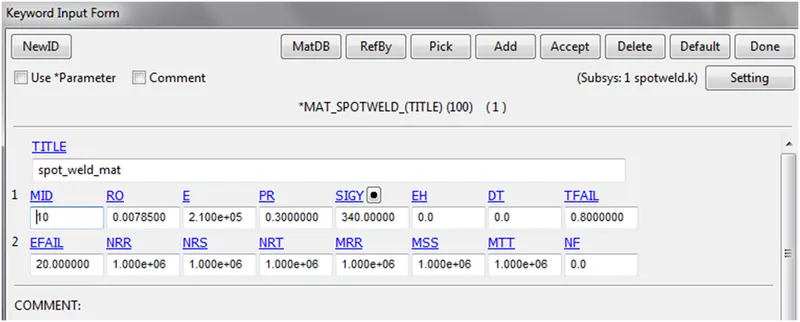
While creating the MAT 100 spot weld material we have to specify the time to fail (TFAIL) for the spot weld. TFAIL in analysis is 0.8 sec.
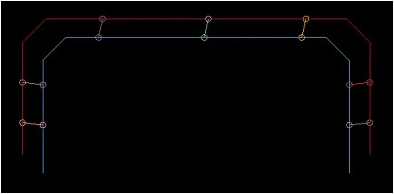
- Beam Spotweld Creation
Mesh > element generation > beam > pick 2 nodes from the two parts equally spaced.
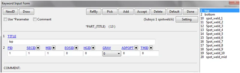
- Assigning Property to the parts.
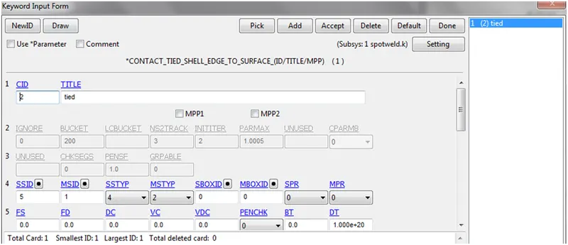
- Assigning contact for beam spot weld:
CONTACT_TIED_SHELL_EDGE_TO_SURFACE is used. The beam spot weld is the slave component and the parts are the master component.
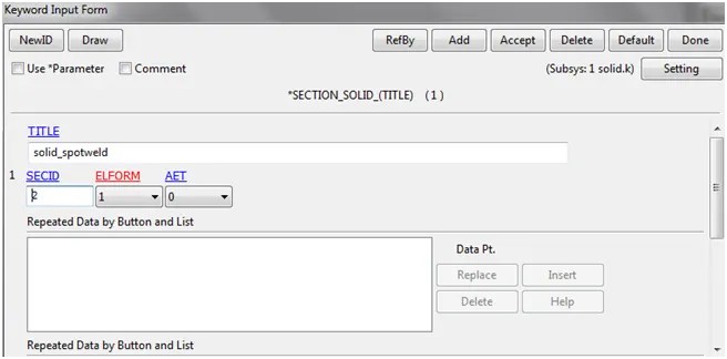
For Solid Spot weld
- Create Section Solid with element formulation (ELFORM 1).
- Same material card is used, (MAT 01 elastic) for the sheet metal parts and (MAT 100 Spot weld) for the spot weld. After which property is assigned to the parts.
3.Solid spot weld creation:
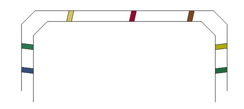
The Solid spot weld is created exactly at the same sot the beam spot weld was created for deriving the exact correlation.
Element tools > Solid > select 4 nodes on one parts and 4 nodes on the other part to create HEX element.
- Assigning contact for solid spot weld:
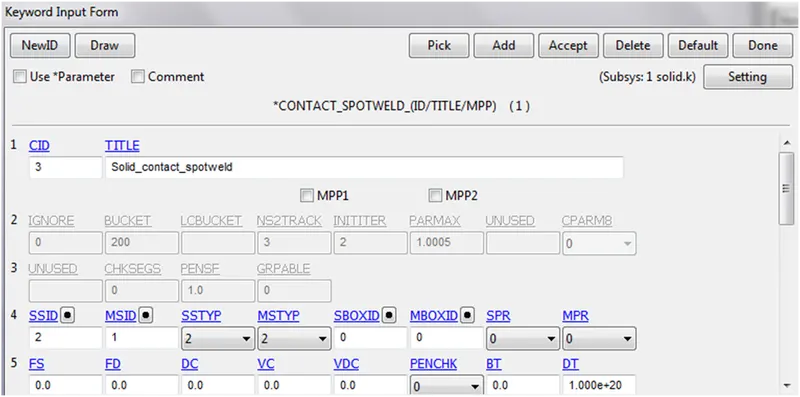
CONACT_SPOTWELD is used. In the Solid spot weld the spotweld is the slave component and the parts are the master component.
Comparision of the Beam spotweld and the Solid spotwelds.
Results:
Von mises stress:
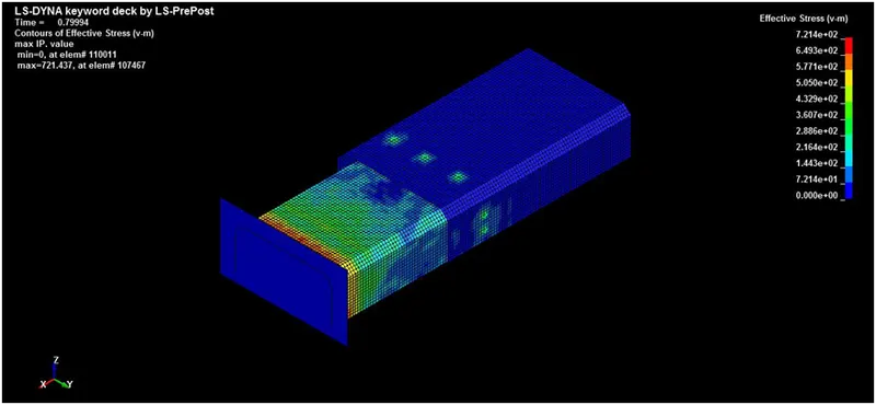
Beam Spot weld:
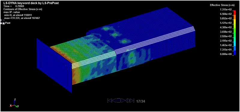
Solid Spotweld:
Observation on stress:
The Von Mises stress for the Solid is higher than the beam spotweld.
Global Energy
Beam Spot weld:
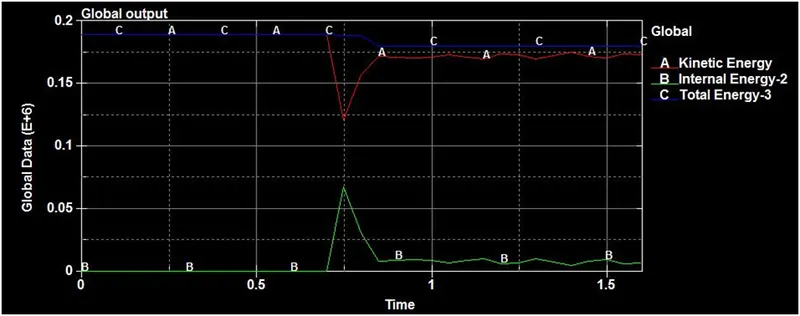
Solid Spotweld:
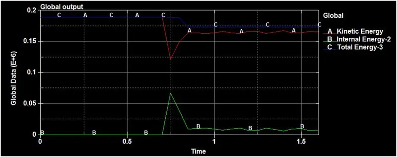
Observation:
The global energies are almoste similar
Axial forces:
Beam Spot weld:
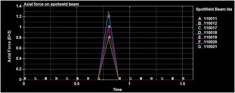
Solid Spotweld:
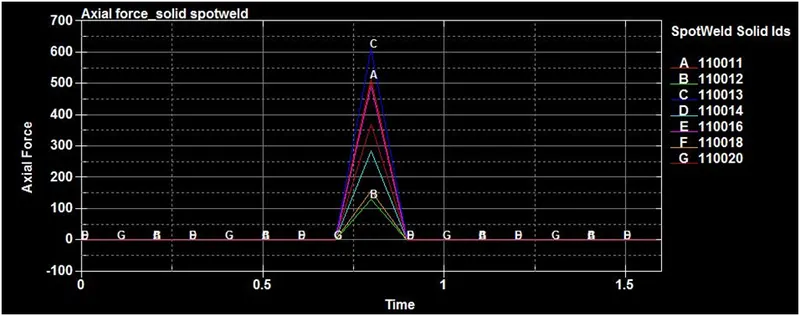
Observation on Axial forces:
On comparison the beam spot welds records a higher axial force compared to the solid spot weld.
Shear forces:
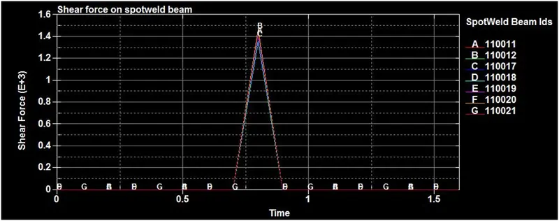
Beam Spot weld:
Solid Spotweld:
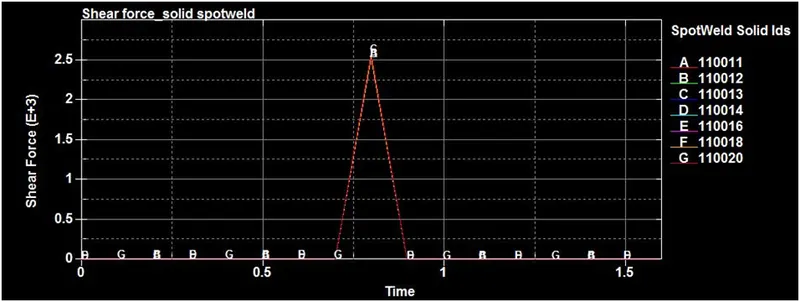
Observation on shear forces:
On comparison the Solid spot welds records a higher shear force compared to the beam spot weld.
Conclusion:
The Spot weld for Beam and Solid elements were modeled and crash analysis was executed.
On comparing, the behavioral characteristics of the solid and beams spotweld can be understood