Week - 5 - Modelling Spotwelds
Aim : Simulation of Crassbox and modeling of spotweld
Procedure :
open LS PrePost and open given file
File >> open >> Ls Dyna Keyword file
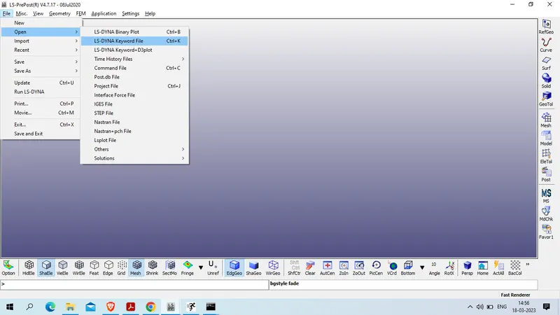
Select the file >> and open
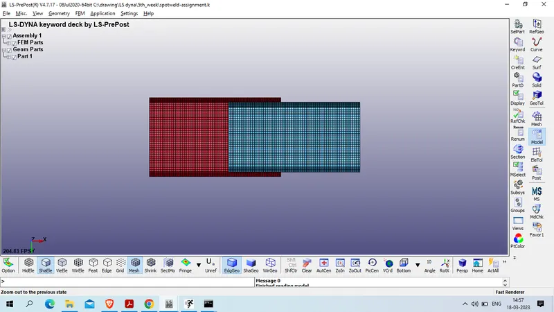
as checked we have only geometry now we will deploy beam element for spotweld in middle of both plate juntion
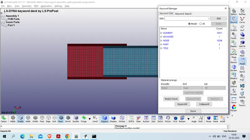
for that we will hide half part as shown below
Element tool >> Blank >> pick element by area
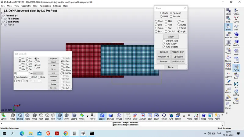
now create beam element as shown below
mesh >> emenent generation >> select beam >> select beam by : TWO_NODE_SET>> select node on 1st part amd node 2 on 2nd part as shown below
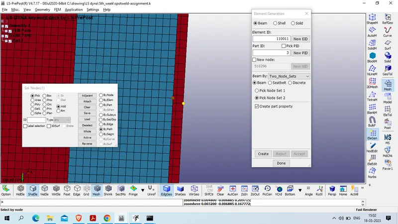
click on create >> accept
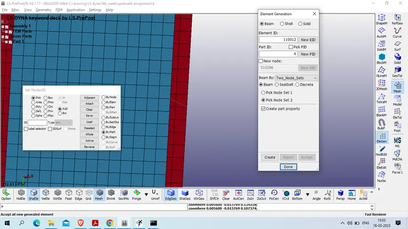
repeat the same process to generate more 4 beam element as shown below are the region fro element
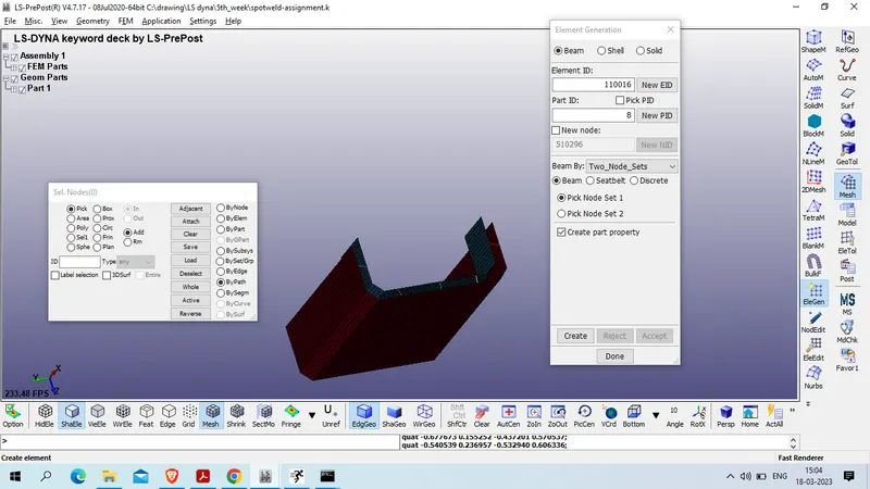
now unhide all element
element tool >> blank >> unblank all element
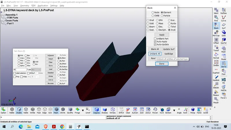
now create node set for all beam element node
model and part >> create entity >> set data>> node_set >> Create >>
Title : BEAM_NODESET
select node of each beam element
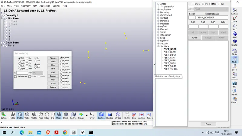
click on apply now create partset id for all parts except beam element
model and data >> create entity >> set data >> SET_PART >> create
title : ALL_PARTSET
select by part and select both part and click on apply
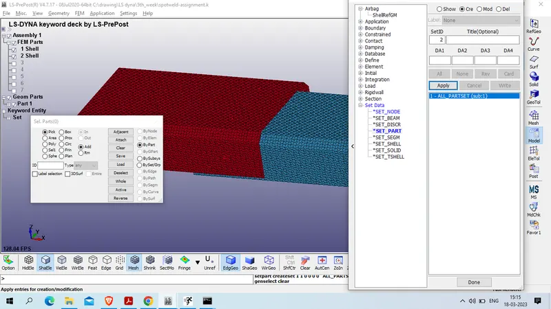
now we will create section for beam and part element
model and part >> keyword manager >> all >> section >> BEAM >> delete all auto generated beam element
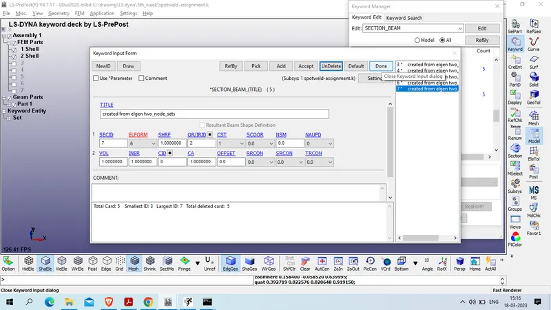
Now create beam section using
Model and part >> keyword manager >> all >> section >> beam
title : SECTION_BEAM
SECID : 1
ELFORM : 9
CST : 1 tubular,
TS1 : 3
TS2 : 3
TT1 : 1
TT2 : 2
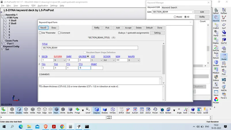
Accept >> done
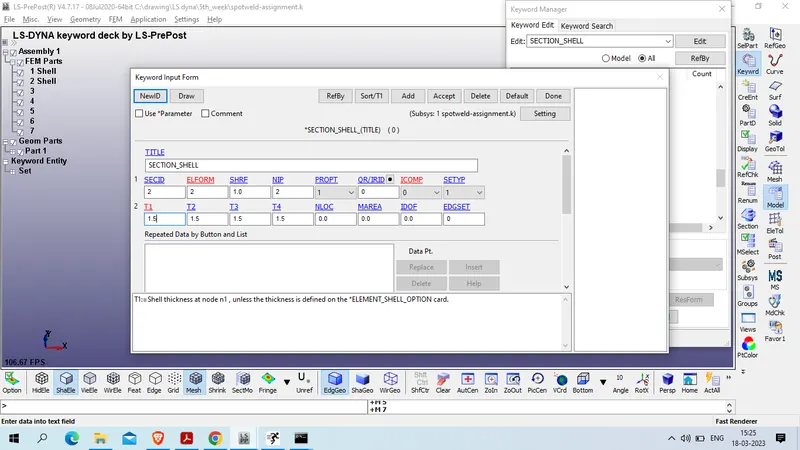
now create shell section
Model and part >> keyword manager >> all >> section >> shell
title : SECTION_SHELL
SECID : 2
ELFORM : 2
T1/T2/T3/T4 : 1.5
accept >> done
now create material card for beam and part and we will use g-mm-ms unit system
Mass: Gram
Length : mm
Time : ms
Force : N
Stress : MPa
Energy : N-mm
Density Of steel : 7.83e-03 g/mm^3
Young's modulus of steel : 2.07e+05 MPa
Velocity at 50 KMPh : 13.889 mm/ms
model and part >> keyword manager >> all >> mat >> 071_CABLE_DISCREATE_BEAM>> delete all auto genertade Material card
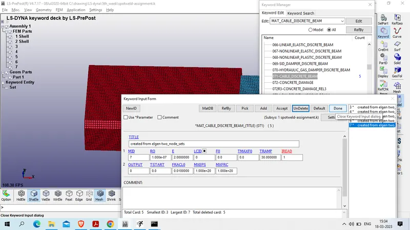
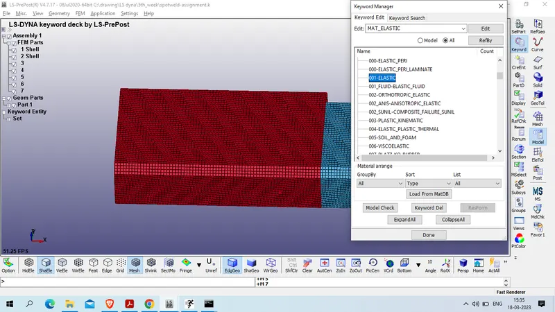
Now create elastic material 001_elastic for all part element
model and part >> keyword manager >> all >> Mat >> 001_ELASTIC
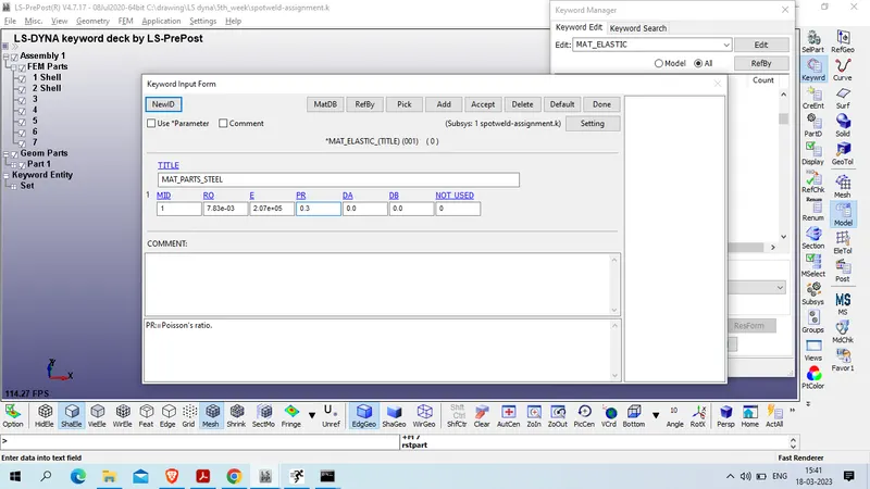
Title : MAT_PARTS_STEEL
MID :1
Density Of steel : 7.83e-03 g/mm^3
Young's modulus of steel : 2.07e+05 MPa
Poission Ratio : 0.3
Accept >> done
Create material for spotweld
Model and part >> keyword manager >> all>> mat >> 100_spotweld
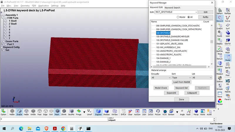
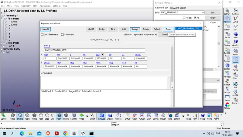
Title : MAT_SPOTWELD_STEEL
Mid : 2
Density Of steel : 7.83e-03 g/mm^3
Young's modulus of steel : 2.07e+05 MPa
Poission Ratio : 0.3
SIGY: 350 MPa
TFAIL: 1.5
EFAIL : 20
NRR : 10000
NRS : 10000`
NRT : 10000
NRR : 90000
MSS : 90000
MTT : 90000
Accept >> done
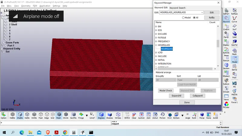
Create hourglass card
model and part >> keyword manager >> all >> Hourglass >> Hourglass
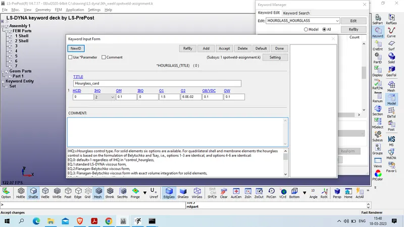
Title : Hourglass_card
HGID : 1
IHQ : 2 :Flanagan-Belytschko viscous form
Accept >> done
now assign Section , Material and hourglass to the part ID
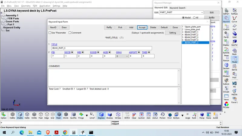
model and part >> keyword manager >> model >> part >> Part
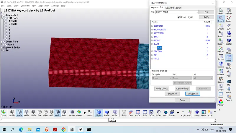
as we have 7 parts , 1st two parts are part body and rest 5 part are spotweld
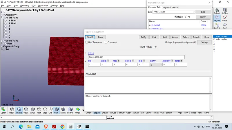
for 1st part
title : Upper_palte_part
PID : 1
SECID : SHELL_SECTION : 2
MID : STEEL_MAT_ELASTIC :1
HGID : 1
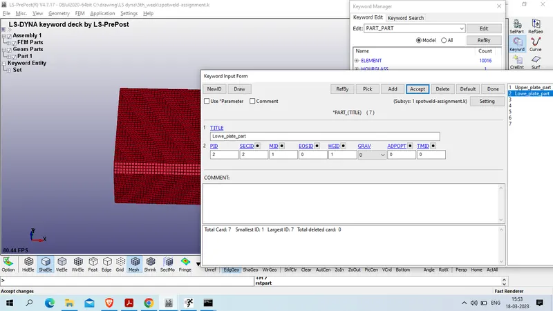
for 2nd part
Title : LOWER_PLATE_PART
PID : 2
SECID : SHELL_SECTION : 2
MID : STEEL_MAT_ELASTIC :1
HGID : 1
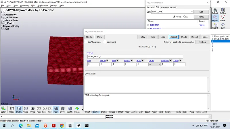
for 3rd to 7th part
title : Beam_Part_1/2/3/4/5
PID : 3/4/5/6/7
SECID : 1 (SECTION_BEAM)
MID : 2 ( MAT_STEEL_BEAM)
now create cross-section to measure the cross-sectional force during the crass
to create cross-section on middle of both part
model and part >> create netity >> database >> cross_section >> create
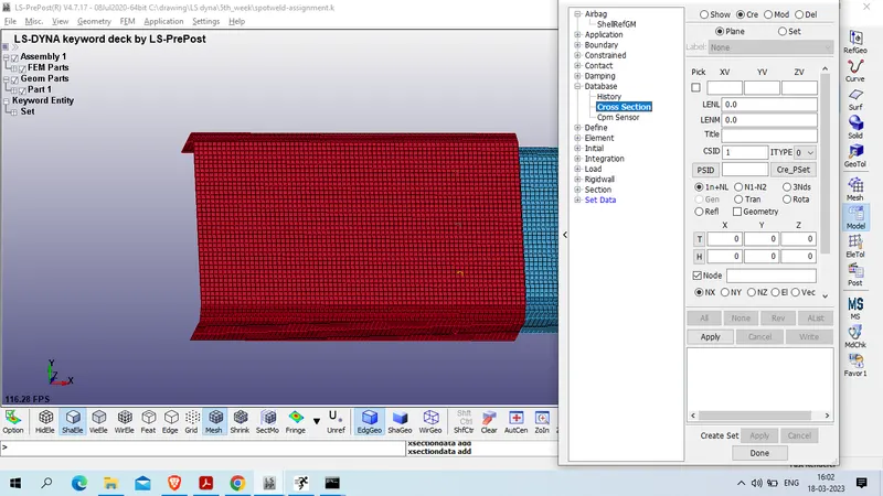
select : plane
select node on middle of component in our case we have node id 503890 and node and 506933 for lower and upper plate respectively .
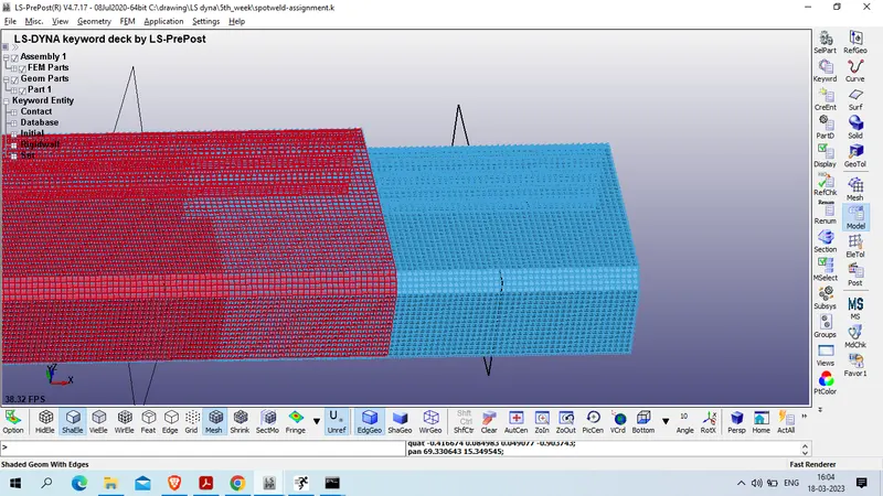
now craete rigid wall 10mm away from the start node
Model and part >> create entity >> rigid wall >> rigidwall >> Create >> Planner >> 1n+ NL
select node by pick option and provide translation of -10 mm magnitude in x axis
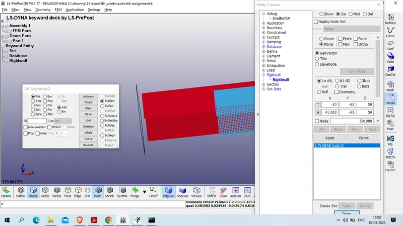
apply >> done
Now create velocity card for the movement of crassbox
Model and part >> keyword manager>> all >> intial >> velocity
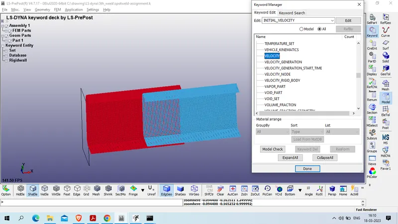
for NSID >> create new Nod_entity
Title : ALL_NODE_SET_PART
SETID : 2
select node by part : select all 2 part ( except beam element )
ALL_NODE_SET_PART
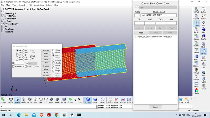
click on apply
prvide Vx : -13.889
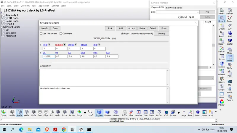
Accept >> done
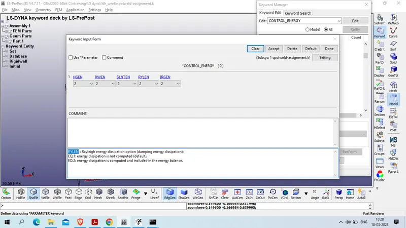
now define control_enery card
model and part >> keyword manager >> all >> control >> energy
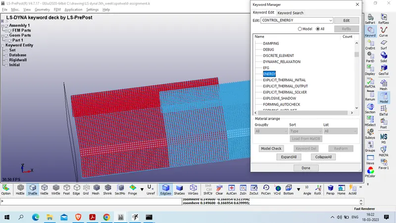
HGEN : 2
Rwen : 2
SLNTEN : 2
RYLEN : 2
IRGEN : 2
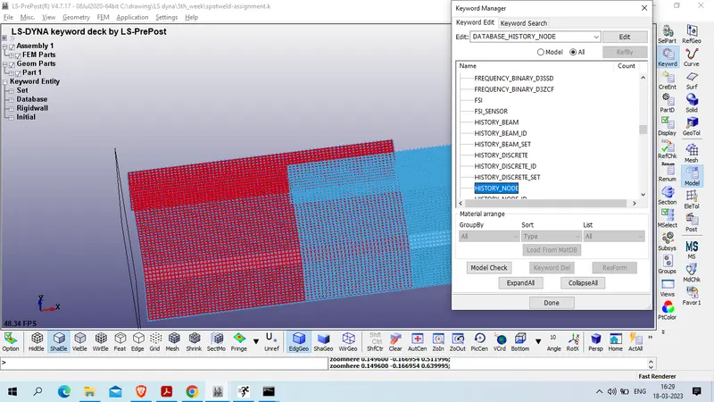
Now craete history node
Model and part >> keyword manager >> all >> database >> History_node
ID1 : 506933
ID2 : 503890
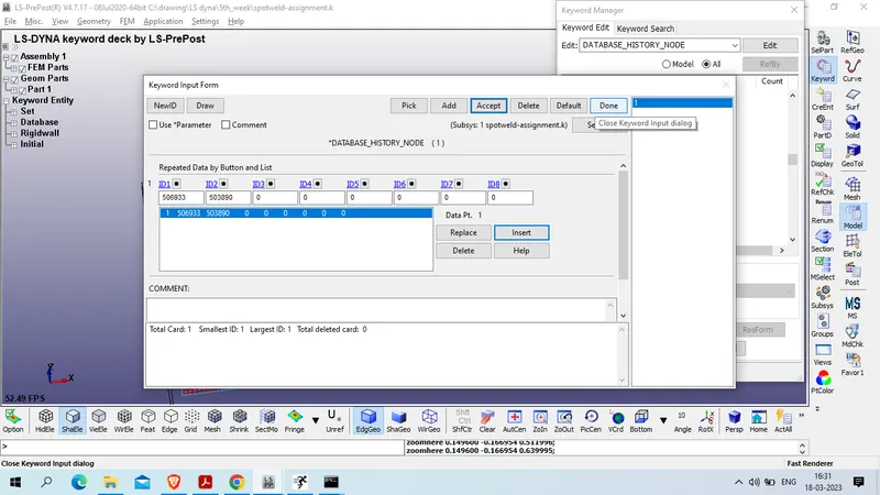
Insert >> accept >> done
Create contact between Beam element and part using beam node as slave and part element as master
Model and part >> Keyword manager >> all >> contact >> Tied_shell_edge_to_surface
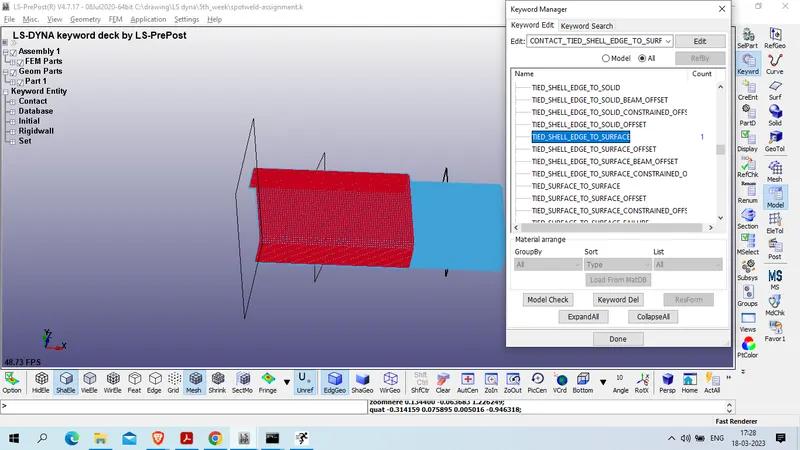
SSYTP : 4 (node set ID for node to surface contact)
MSYTP : 2 ( part set ID,)
SSID:=Slave segment set ID : 1 ( Beam ELEMENT NODE SET)
MSID:=Master segment set ID : 1 ( PART_SET)
FS AND FD : 0.8 ( STEEL TO STEEL FRICTIONAL COEFFICIENT )
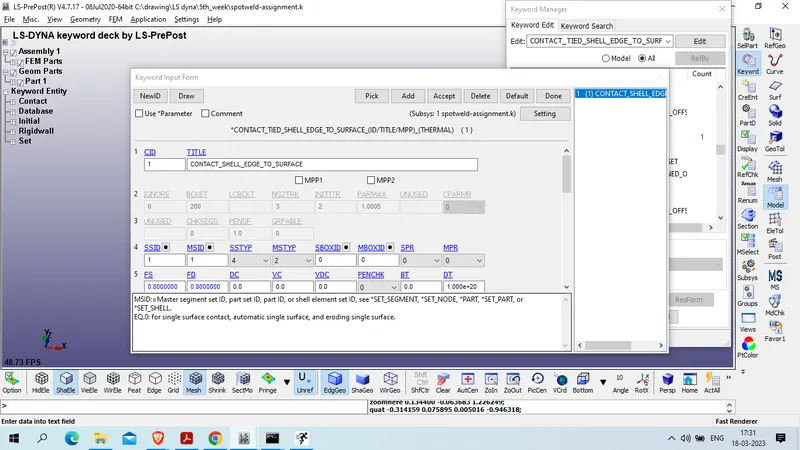
accept >> done
NOw define self contact for all part element
Model and part >> keyword manager >> all >> contact >> AUTOMATIC_SINGLE_SURFACE
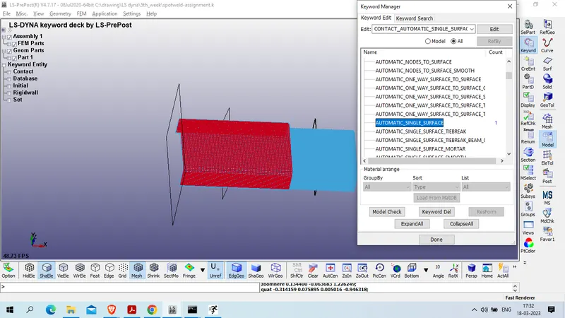
SSYTP : 2 (PART_SET_
MSYTP : 2 (PART_SET)
SSID : 1 ( PART_SET)
MSID : 1 (PART_SET)
FS & FD : 0.8 ( steel to steel frictional coeffiecient )
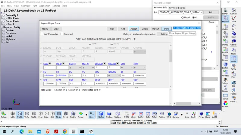
accept >> done
now define termination card '
Model and part >> keywprd manager >> all >> control >> termination
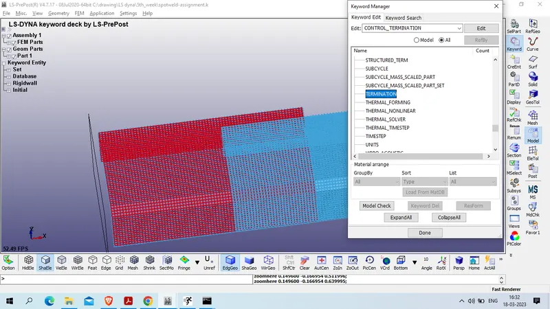
ENDTIM: 3
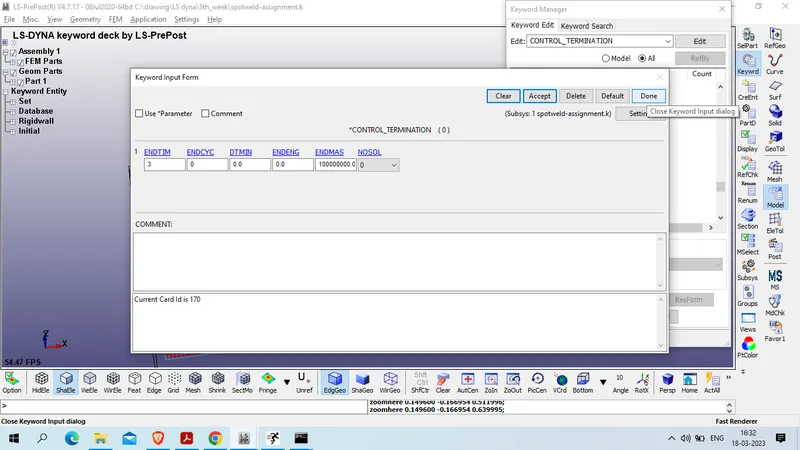
accept >> done
now define output card
1. D3plot
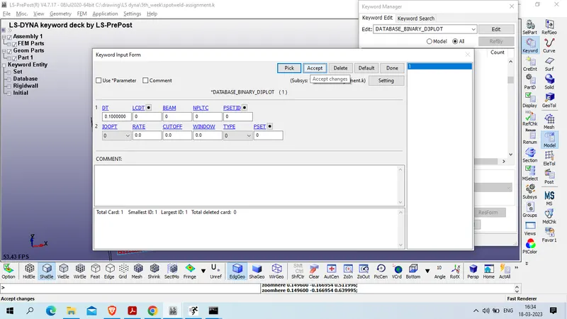
Model and part >> keyword manager >> all >> database >> BINARY_D3Plot
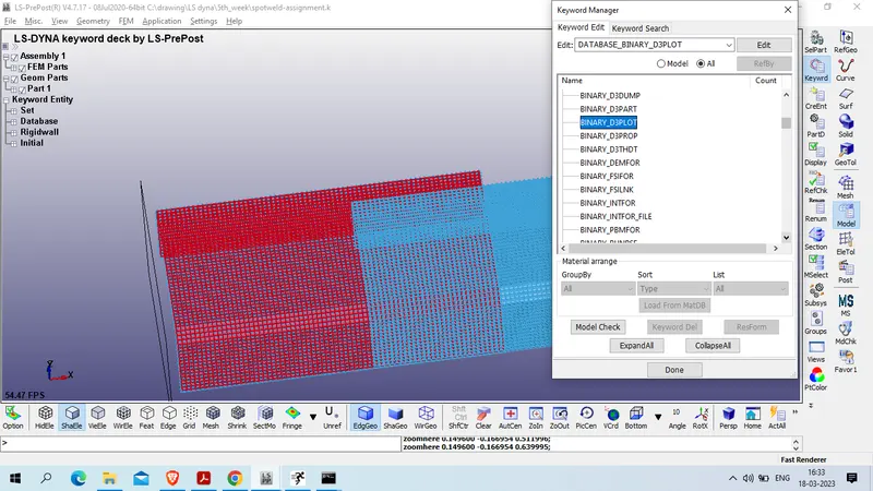
Dt : 0.1 >>accept>> done
2. ASCII_OPTION
Model and part >> Keyword manager >> all >> Database >> ASCII_OPTION
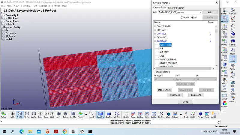
Set Default DT : "0.1" and Default Binaty :" 3"
request for below output
ELOUT - Element Output Data
GLSTAT - Global Statistics
MATSUM - Material Energies
NODOUT - Nodal Displacement/Velocity/Acceleration data
RCFORC - Resultant Interface Forces
RWFORC - RigidWall Forces
SECFORC- Cross Section Forces data
SLEOUT - Sliding Interface Energies
SWFORC - Spotweld Nodal Constraint Reaction Forces
for all DT = 0.1
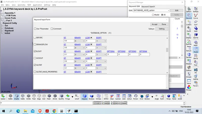
accept >> dnoe
now save the mode in seperate folder
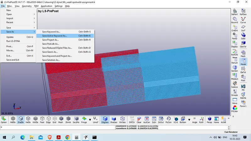
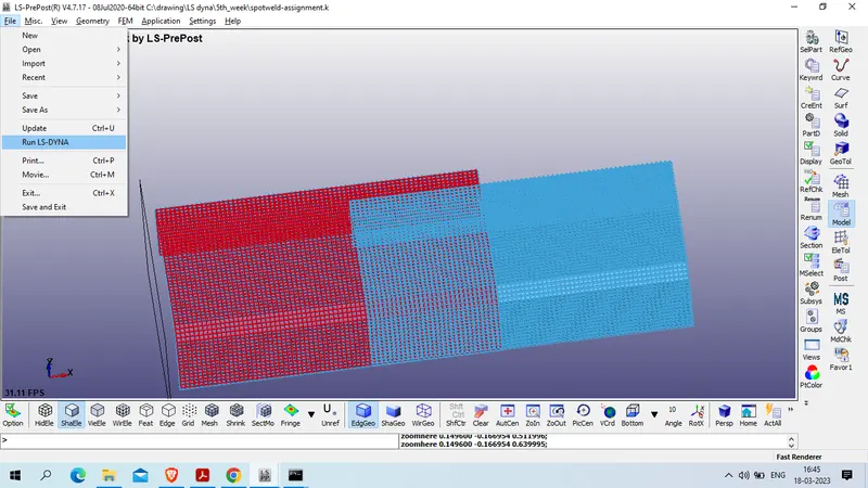
now run the model using
File >> run LS-DYNA
Select new file which we saved .
and click on run
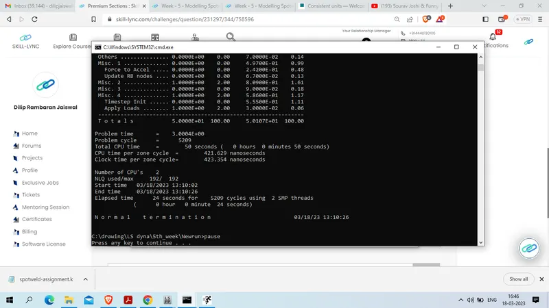
Our simulation in terminated normal .
Case 2 : we will import privious model and delete beam element and create solid hexa element
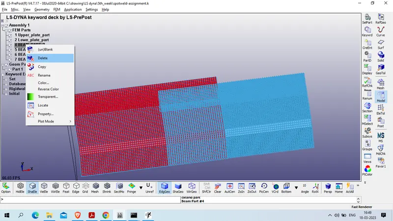
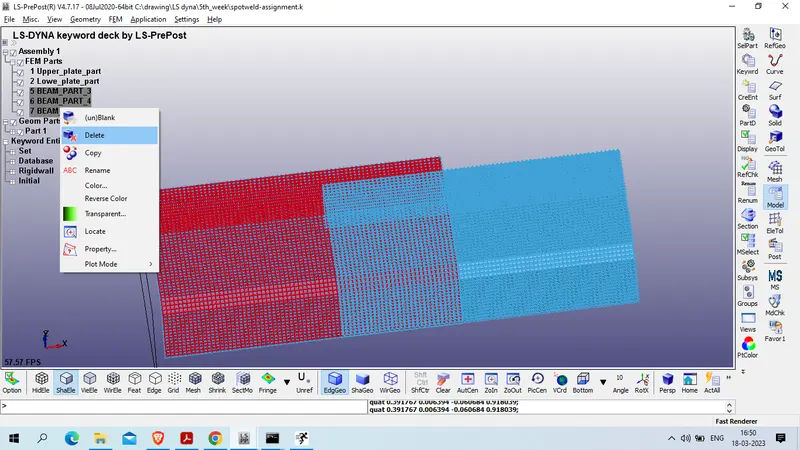
now to create hexa solid element in place of beam element
1st wwe will hide half element as previous
Element tool >> element edit >> blank >> select by area
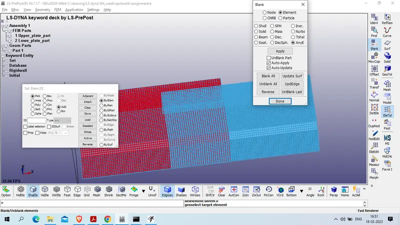
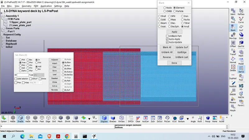
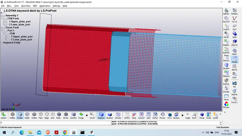
now create hexa element on the place of beam element
Mesh >> element edit >> create >> Hexa
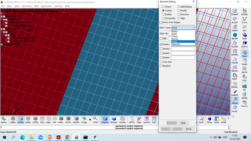
Select 4 node on lower part and respective 4 node on upper part in anticlock wise and click on accept
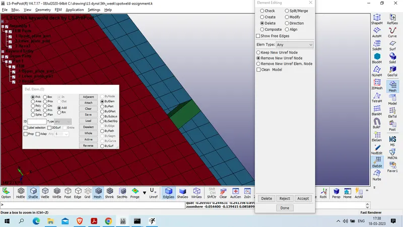
create same process to generated more 4 hexa element as shown below
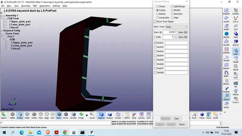
Now unhide all element
element tool >> black >> unblank all
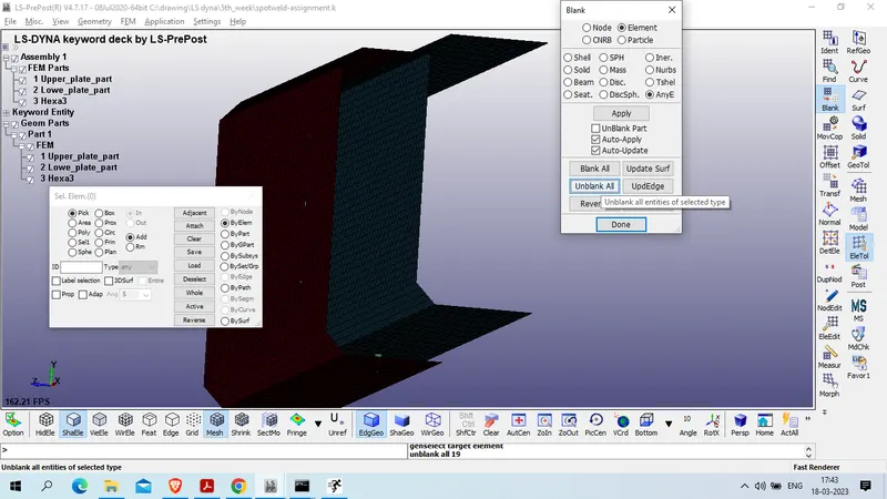
Now delete beam section and create solid section
model and part>> keyword manager >> all >> section >> solid
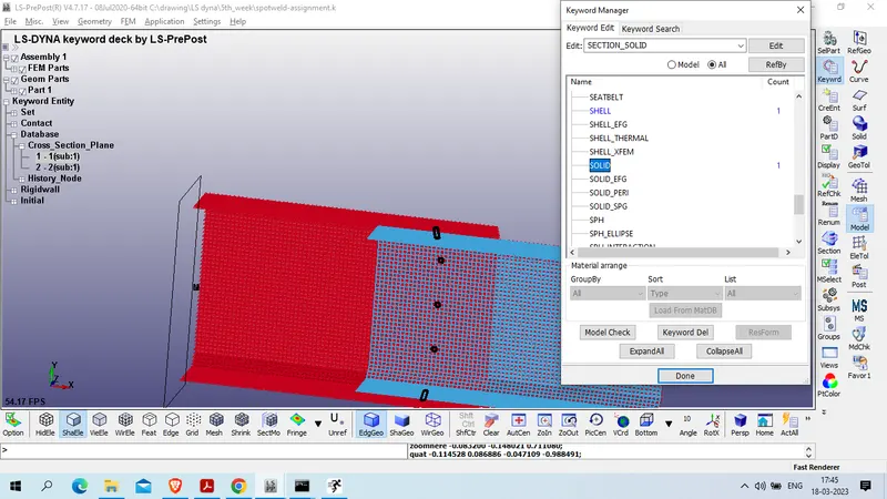
Title : SOld_spotweld_section
SECID : 1
ELFORM : 1
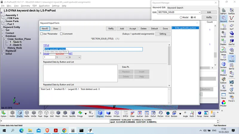
Accept done
Now create solid section for all hexa element
Model and part >> create entity >> set Data >> solid
Title :All_spotweld
SETID : 1
select all solid hexa element and apply >> done
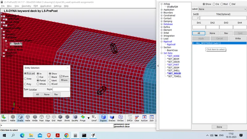
goto part and create part id for hexa solid element
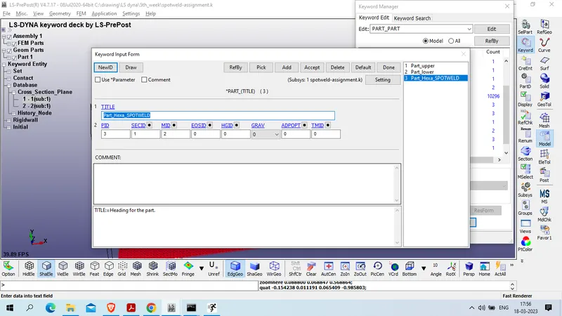
model and part >> keyword manager >> all >> Part >> part >>
Title : Part_Hexa_SPOTWELD
PID : 3
SECID : 1
MID : 2
Noe modeify contact
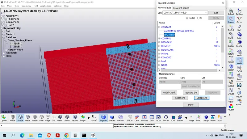
delete tied contact and craete spotweld
model and part >> keyword manager >> all >> contact >> spotweld
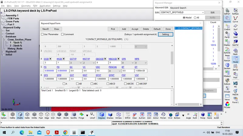
SSTYP : 3
MSTYP : 2
SSID : 3
MSID : 1
FS & FD : 0.8
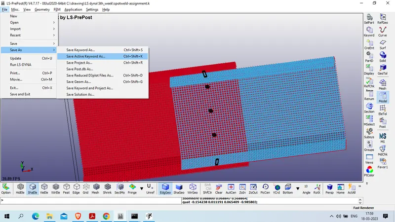
Now save the file in different folder
file >> save as >> select location and rename file
now run the file
file >> run LS DYNA
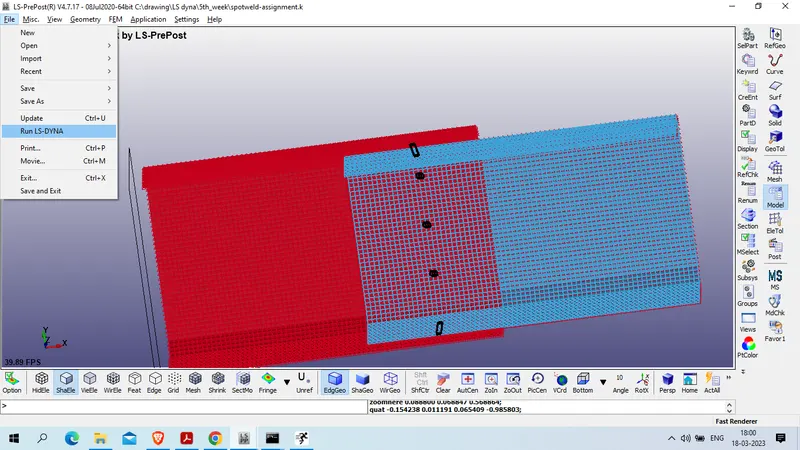
select new file and run
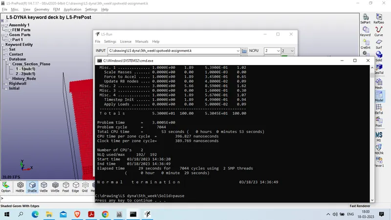
Result
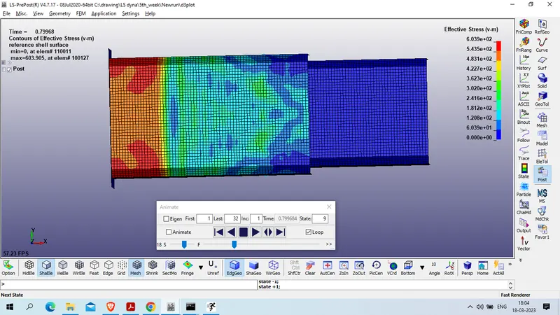
1. Von Mises stress in case 1
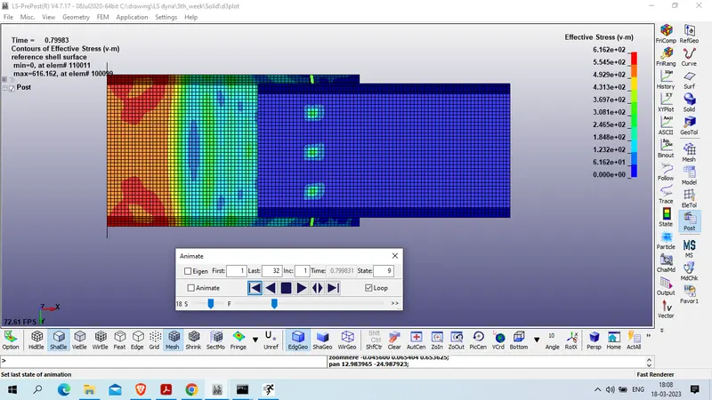
2. Von Mises Stress in case 2
Plots
3. Global energies in case 1
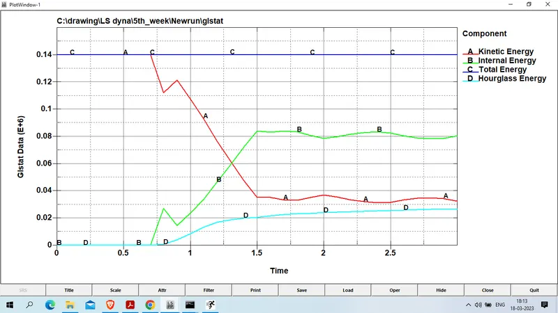
4. GLobal Energies in 2nd case
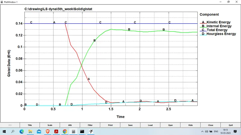
as we obserbed that hourglass energy developed more in case 1 compraed to case 2
5. Axial force developed at the beam element in case 1
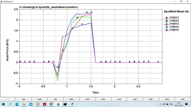
6. axial force developed in case 2 on solid soptweld element
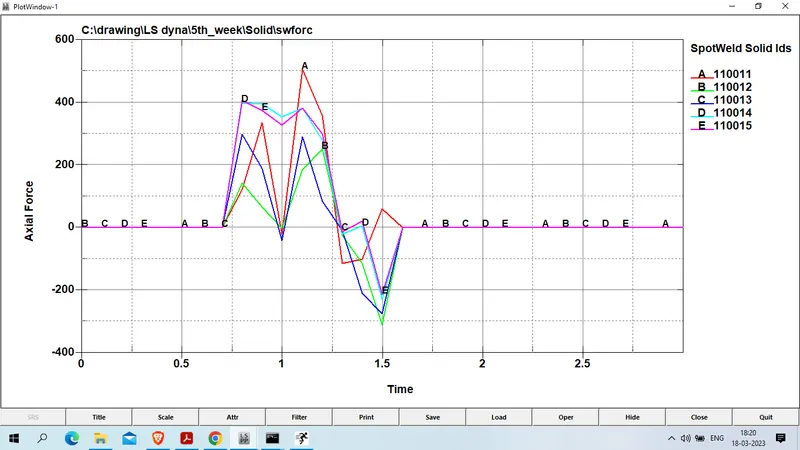
beam experiences more axial load compared to the solid element.
7. Shear Force on beam element in case 1
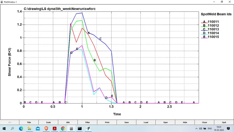
8. Shear force on solid element in case 2
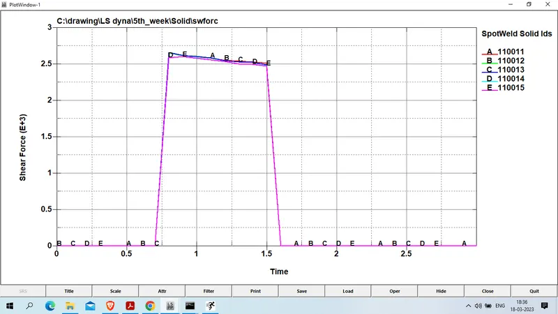
Shear forcewe obserbed in 2nd case more than in case 1.
Conclusion :
1) we had succesfully run the simulation for all 2 case and compared the axial and shear forces in both case.
2) When a beam element is used for a spotweld, the axial load is higher than normal which may lead to earlier failure if force-based failure criteria are used.
3) so solid element is more suitable to model the spotweld it has 4 nodes in contact and has better axial and shear capabilities.