Week - 5 - Modelling Spotwelds
Aim:
For the given model, beam weld and solid spot weld are assigned in a symmteric manner and compare the axial force and shear force results.
Procedure:
Unit System I adopted as : gm-mm-ms
Case 1: Beam Weld
Step 1: Import the .k file
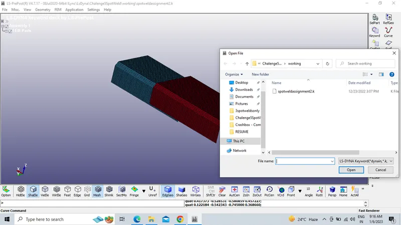
Step 2: Model – Create entity – Rigid wall .
Creating rigid wall in that I have adopted planar option.
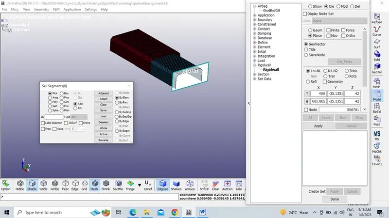
Step3: Checking and changing the orientation of the rigid wall plane because if both the bracket model and rigid wall in same direction during simulation given model penetrates to the rigid wall.
Since it is in opposite direction, change the normal vector direction
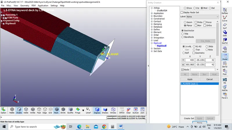
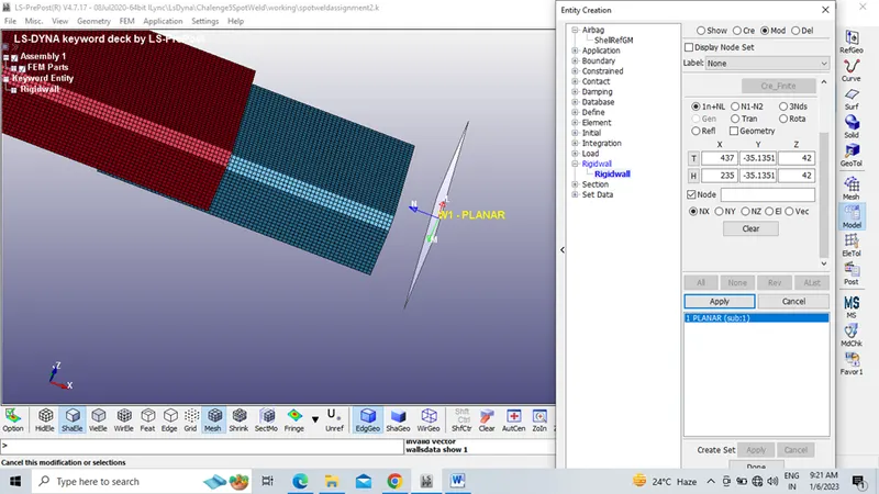
Changing the head and tail values and thereby with the help of translate option rigid wall placed in required direction
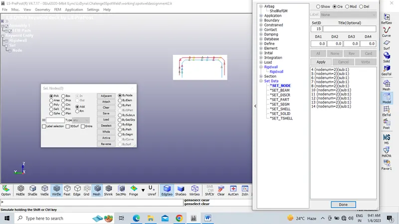
Step 4: Model – Create Entity – Set Data- Set Node.
Creating at least 3-7 node sets to define the beam element
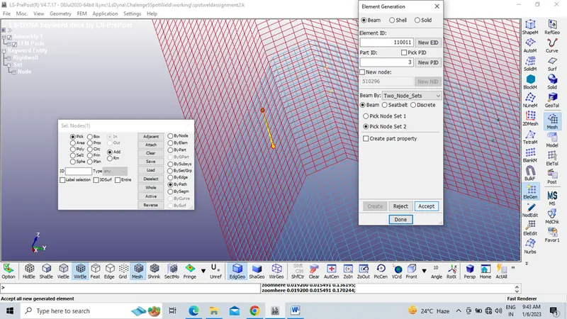
Step 5: Mesh- Element Generation-Beam-Two Node sets
Creating beam element between the two node sets
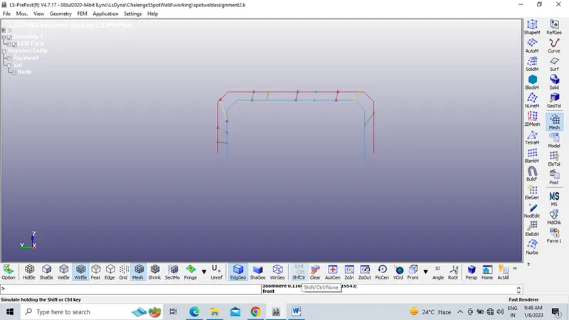
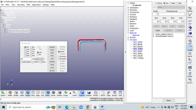
Step 6: Model – Create Entity – Set Data- Set Part.
Creating set part for the assigned beam elements and bracket
Step 7: Model-Keyword Manager-Initial-Velocity
Creating initial velocity to the specimen as 13.89 mm/ms
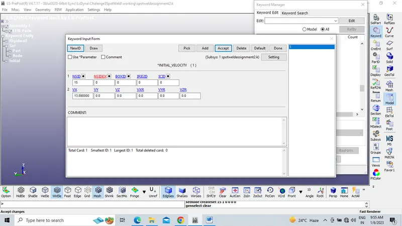
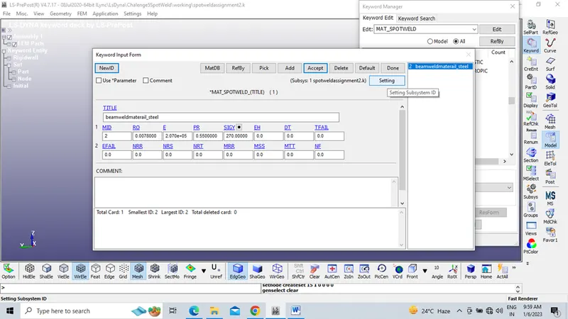
Step 8: Model-Keyword Manager –MAT- 024 Piecewise Linear Plasticity, MAT-100-Spot Weld
Creating material as steel to the bracket (Given model)
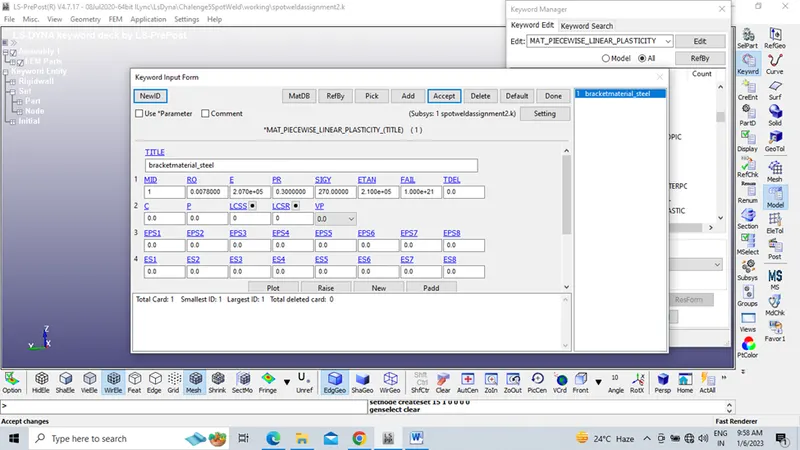
Creating weld material as steel
Step 9: Assigning bracket thickness as 1.5mm and weld material thickness as 2.5mm.
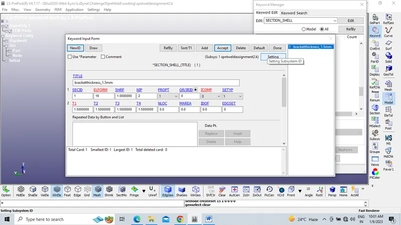
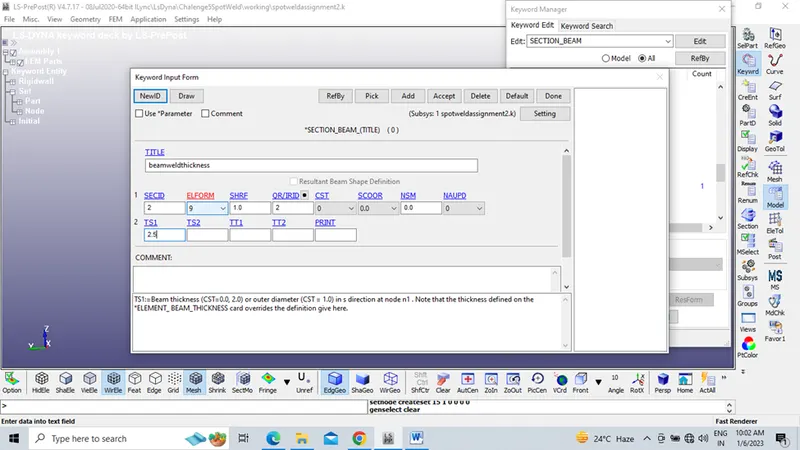
Step 10: Assigning material card piecewise linear plasticity and spot weld and section to the Part card manager.
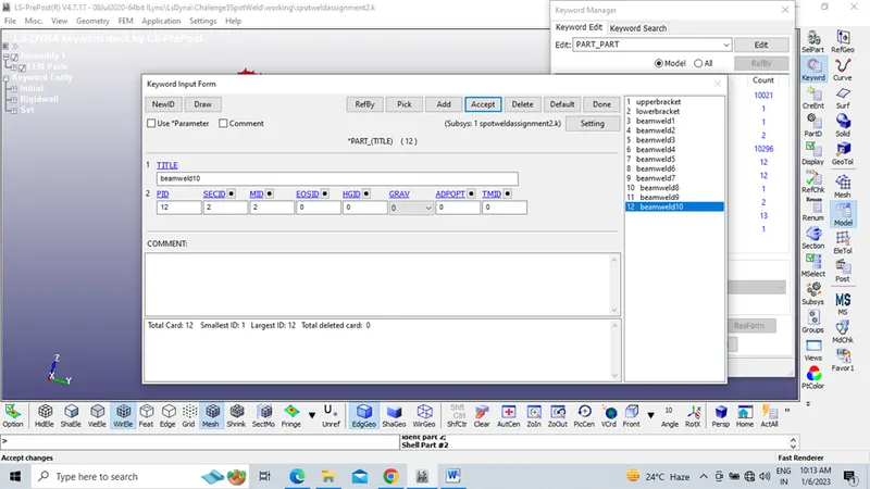
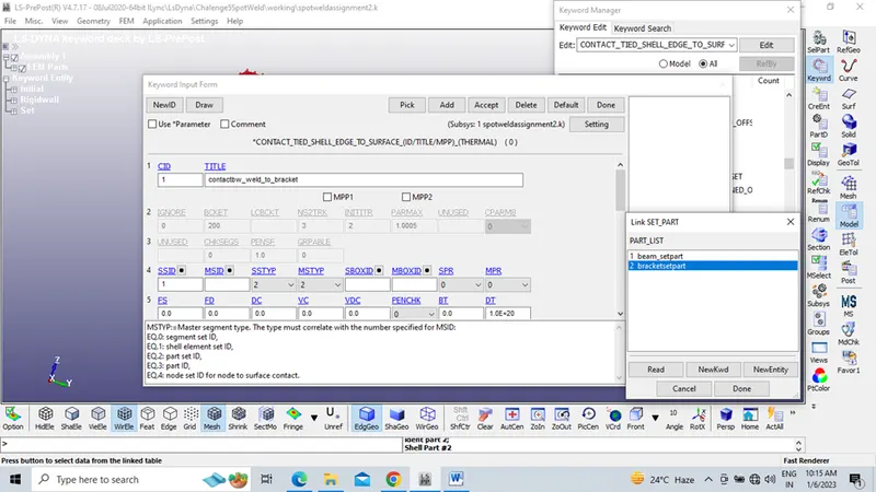
Step 11: Contact-Tied Shell Edge to Surface
Assign contact between weld to bracket in this slave assigned to beam weld and master assigned to bracket.
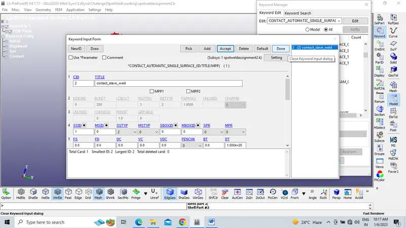
Contact-Automatic Single surface
In this contact Automatic single surface slave assigned as spot weld part set.
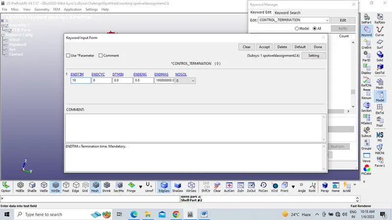
Step 12: Model- Keyword manager -Control -Termination as 10ms
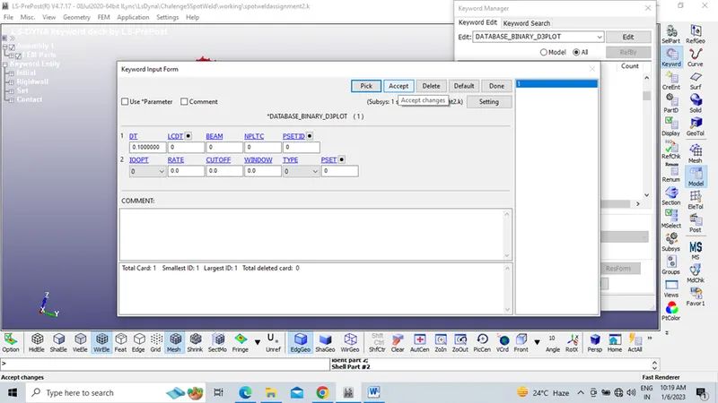
Step 13: In order to fetch the output results like vonmises stress and Effective Plastic
Strain assign Database - Binary d3 plot
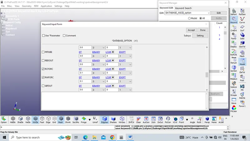
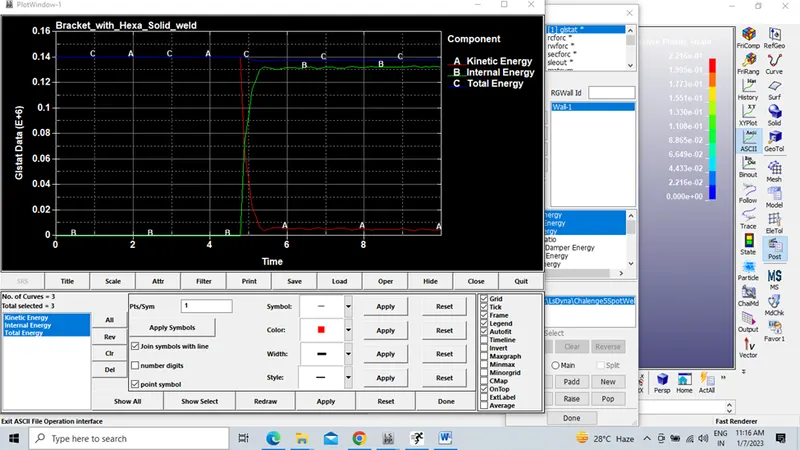
Step 14: Database- ASCII option select GLSTAT- Global Statistics, RCFORC- Reaction force, RWFORC- Rigid wall force to get the output results like Total Energy, Potential energy, Kinetic energy, Resultant force.
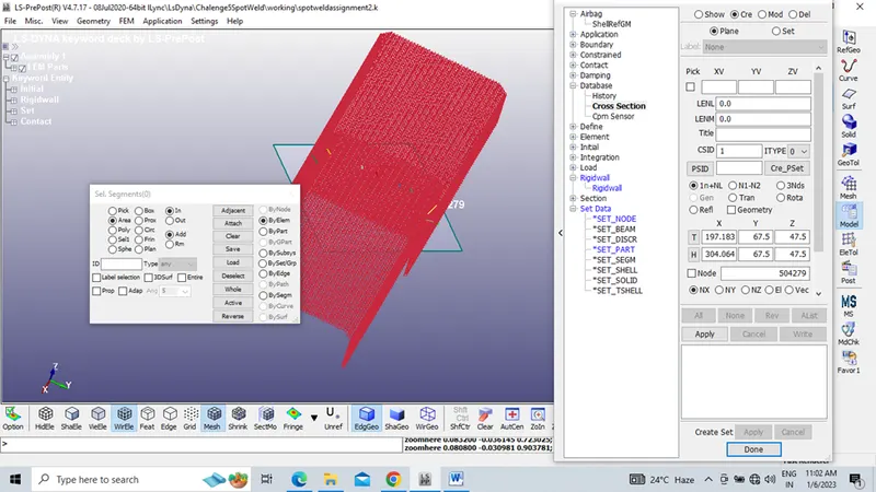
Step 15: Model- Create entity- Database – Cross Section and history
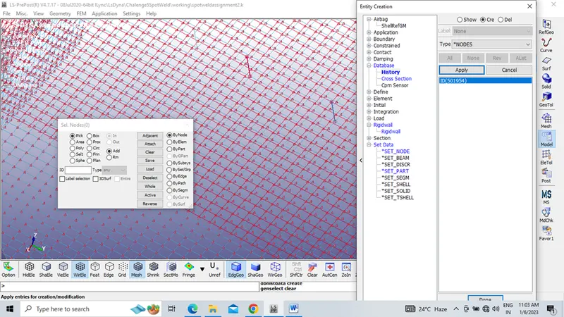
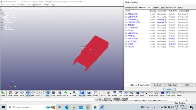
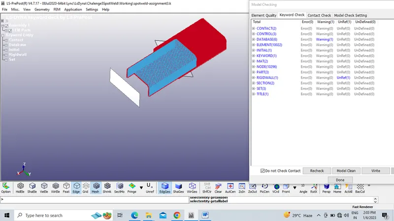
Step 16: Once all the data cards assigned in keyword manager go for Model check.
Since no errors are there.
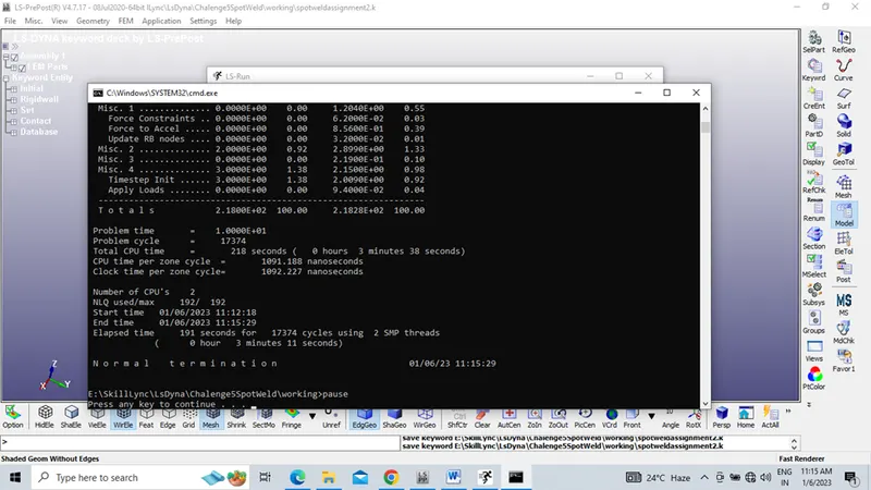
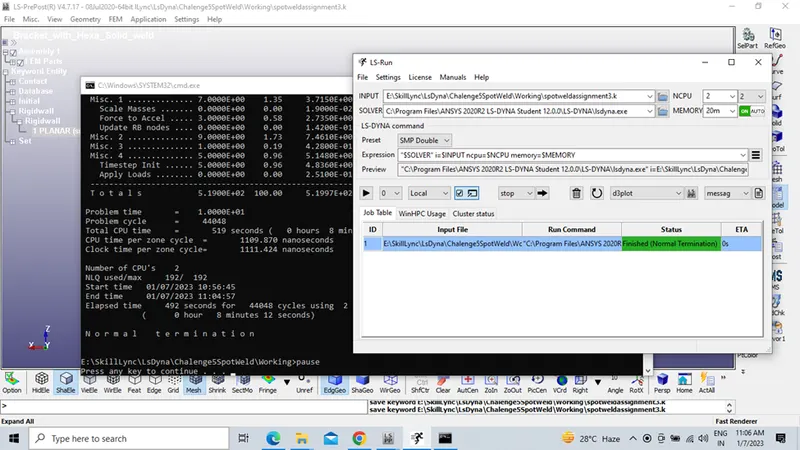
Step 17: Hence Run the .k file in LSRUN Manager.
Results shows as Normal termination
Case 2: Solid Weld
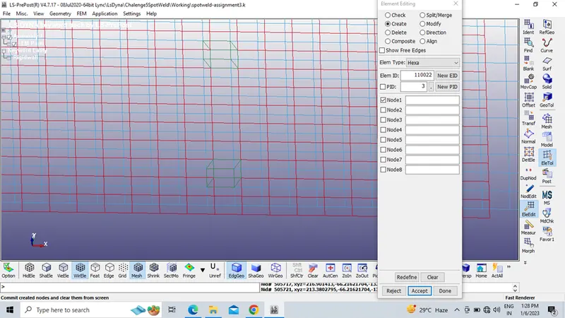
Step 1: Element Tool- Element Edit.
Creating Hexa solid weld in a symmetric manner ( Assign 3-7 Hexa welds)
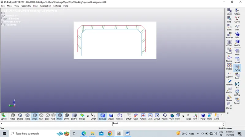
Step 2: All other steps like are same as beam weld
MAT – 024 Piece Wise linear plasticity, 100-Spot Weld
CONTACT- Automatic Single Surface, Tied Shell Edge to Surface
CONTROL- Termination, Energy, Hourglass
SECTION – Shell, Solid
PART – Assign Steel material to Bracket and spot weld
DATABASE- Binary D3 Plot, ASCII
INITIAL – Velocity
MODEL- CREATE ENTITY- SET DATA-SET PART
Step 3: Model Check done for hexa solid element model
Comparison of Results between Beam weld and Hexa solid Weld
Step 1: Von misses stress compared between beam weld and solid weld
Von misses stress- Beam Weld
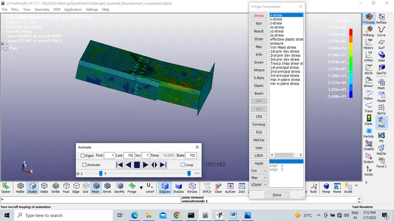
Von misses stress- Solid Weld
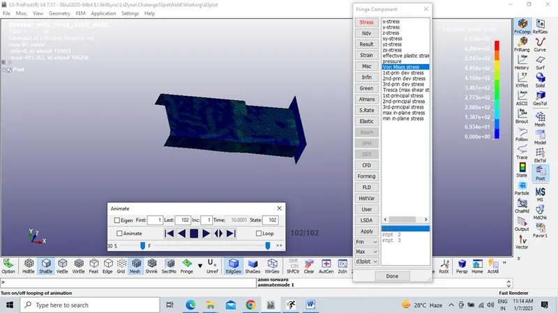
From the above results it is observed that
|
Von misses stress - Maximum |
Element no. |
|
|
BEAM WELD |
173.261 MPA |
104632 |
|
SOLID HEXA WELD |
693.363 MPA |
106258 |
The solid hexa weld model exhibits maximum vonmises stress value compared to Beam Weld due to its higher weld stiffness
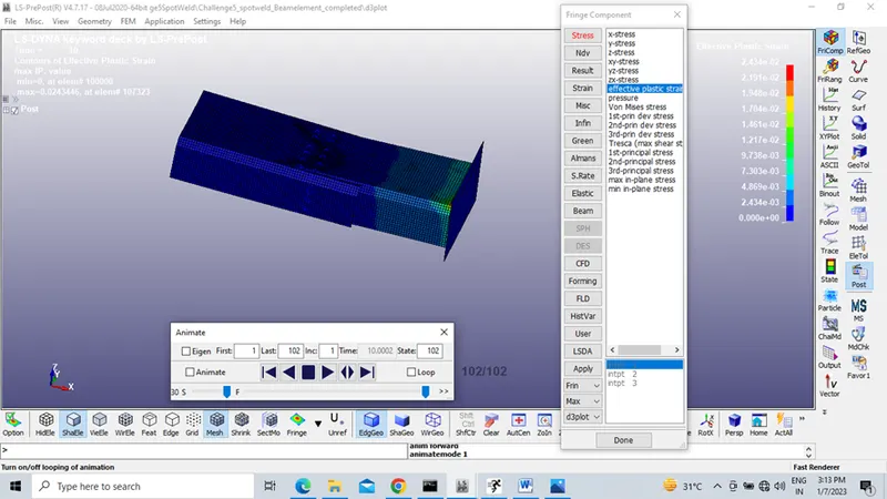
Step 2: Effective plastic strain compared between beam weld and solid weld
Effective plastic strain -Beam weld
Effective plastic strain-solid weld
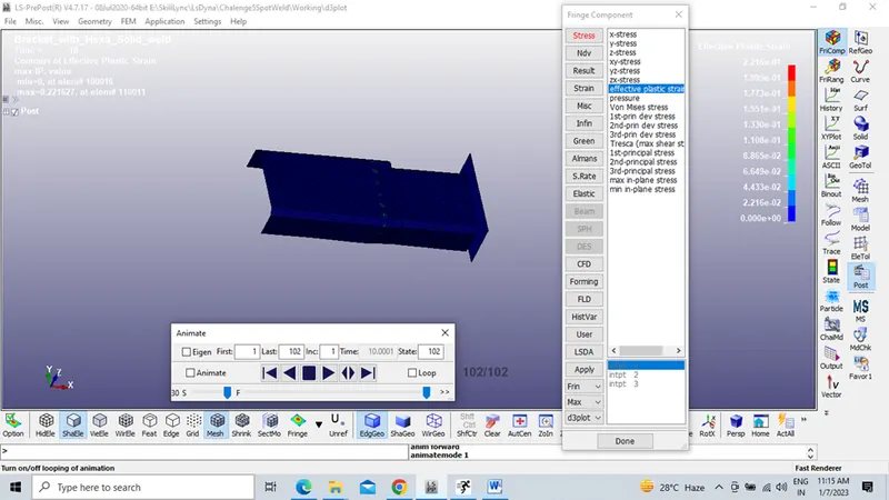
From the above results it is observed that
|
Effective Plastic Strain - Maximum (MPA) |
Element no. |
|
|
BEAM WELD |
0.0243446 |
107323 |
|
SOLID HEXA WELD |
0.221627 |
110011 |
Step 3: Potential energy, kinetic energy, Total energy compared between beam weld and solid weld
Beam Weld
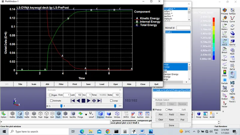
Solid Hexa weld
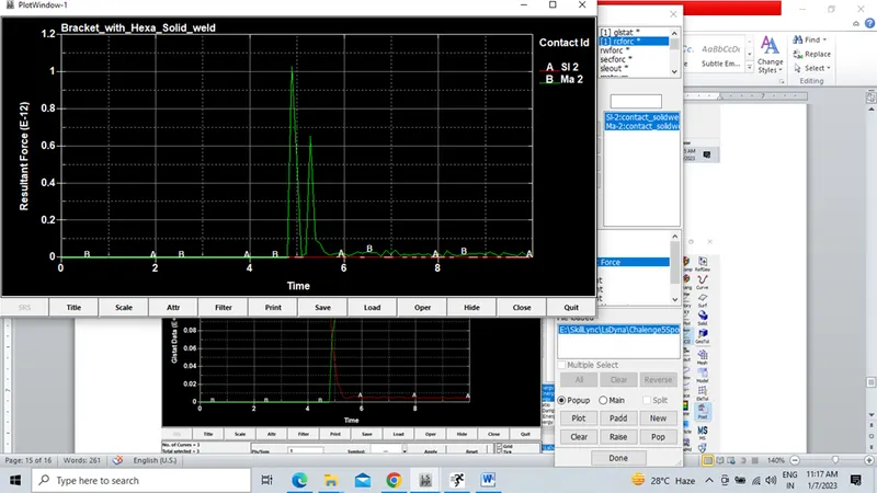
Step 4: Rcforc compared between beam weld and solid weld
Beam Weld
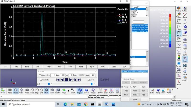
Solid Weld
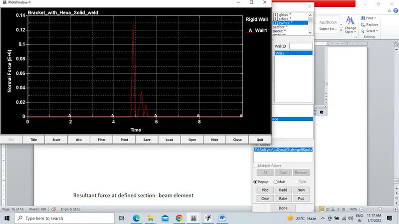
Step 5: Reaction force at rigid wall compared between beam weld and solid weld
Beam element Weld
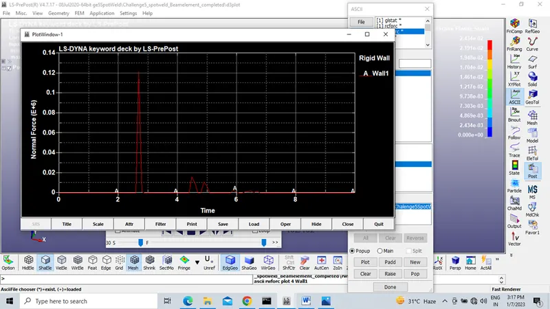
Solid element weld
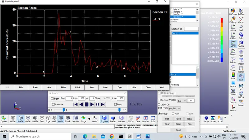
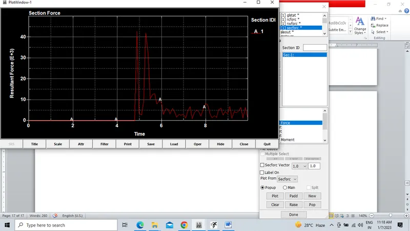
SECFORC compared between beam weld and solid weld -Resultant force at defined section-
Beam element Weld
Solid element Weld
Learning Outcomes:
In this project I have learned about how to assign
- Material card
- Section card for both Beam and Solid Weld
- Initial velocity
- Beam element weld
- Solid Hexa element weld
- Rigid wall
- Part card
- Database: Binary D3plot, Ascii option
- Control card
- Model check
Conclusion:
From the observed results it is concluded that solid hexa weld is best suitable as compared to Beam weld because it exhibits better results.