Week - 5 - Modelling Spotwelds
AIM: The objective of this challange is to model spot welds to join the two sheet metal components using beam elements on first case and solid elements on the second and compare the axial and shear force experianced by the spot welds in both the cases.
PROCEDURE:
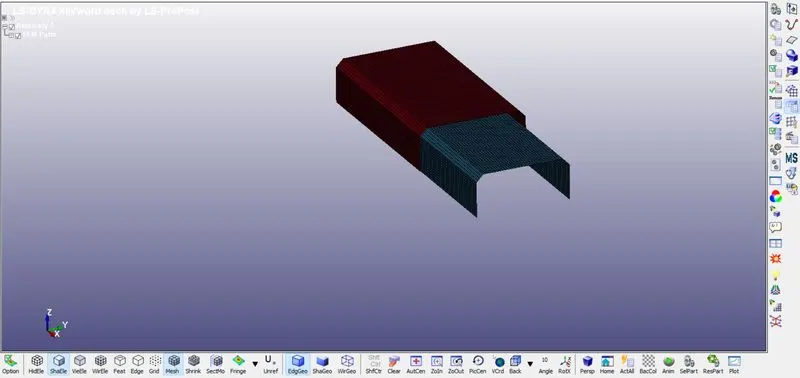
- We will firstly open the .K file in LS-DYNA workspace as given in the challange.
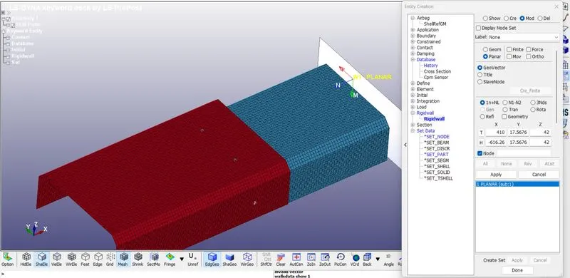
- Now we will create the rigid wall at end of the C-Sectioned metallic componenet.
CASE-1: BEAM SPOTWELD
- SPOTWELD ELEMENT GENERATION:
Spotweld can be created between the two shell components by creating a beam element that is connected at both ends to the nodes of both shell elements.
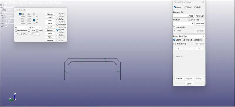
To create a beam element we will select Mesh then Element Generation then Beam and after that selecting two node sets.
- Assigning material properties to the beam elements through Keyword then Material then selecting SPOTWELD100 and entering the material properties, methods to fail the weld, also create material properties, methods to fail the weld, also create material properties.
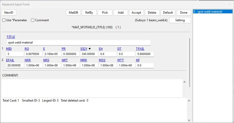
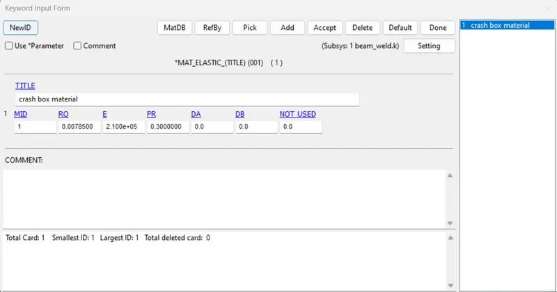
- For this 4 beam element TFAIL (time for spotweld to fail) is created at 0.8ms.
- We will also create self contact for the metal componenet as well as tied contact for the spotweld wheer slaves are the beam elements.
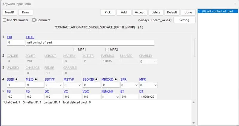
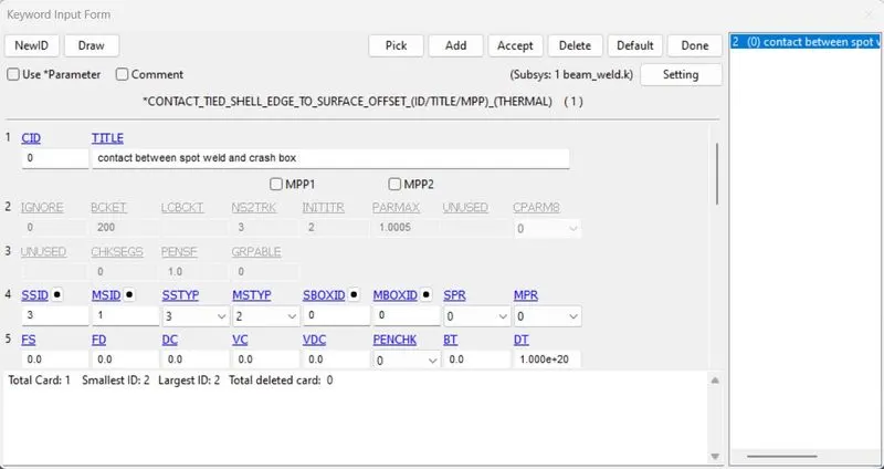
- Now we will create section for the metal component and element formulation 9 is used for creating spotweld.
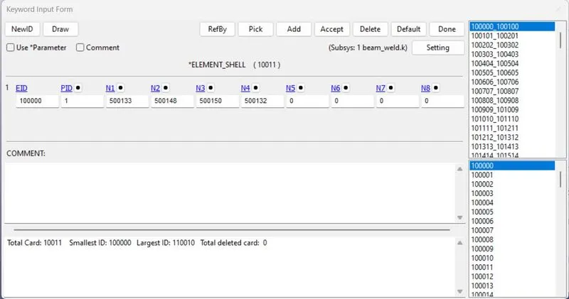
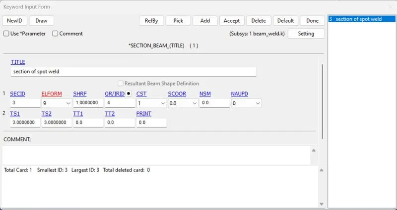
- After this we will assign the material card and Section card to the beam elements in part.
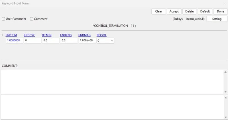
- We will give termination time as 1.6ms as the impact can happen around 0.8ms.
- We have also assign output database as D3Plot, Database_history_node and ASCll options card to the model.
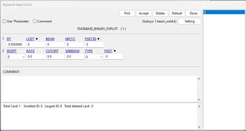
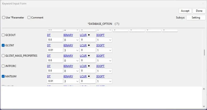
CASE-2 SOLID SPOTWELD CREATION:
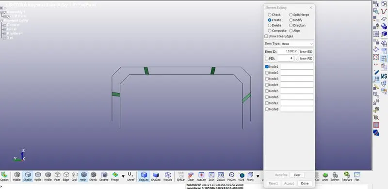
- By using element tools then element editing then for solid we will use hexa as element type, by selecting four node in either of shell element we can create solid element.
- As done above in beam section we will assign material property to the solid element.
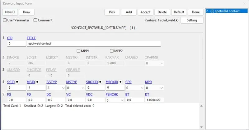
- For contact spotweld for solid element taken as Slave and metal componenet as master.
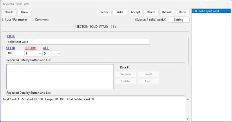
- Creating the section with element formulation as 1 for the solid element.
- Assigning the material id and section id in the part to solid.
- The same control card will be applied here with same temination time.
- And for output also we will be selecting the same ASCll option and D3Plot as well as History Node.
RESULT:
ENERGIES DATA:-
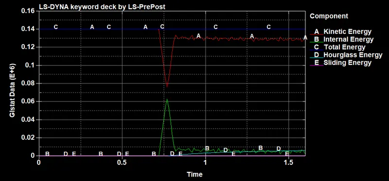
FOR BEAM SPOTWELD:
FOR SOLID SPOTWELD:
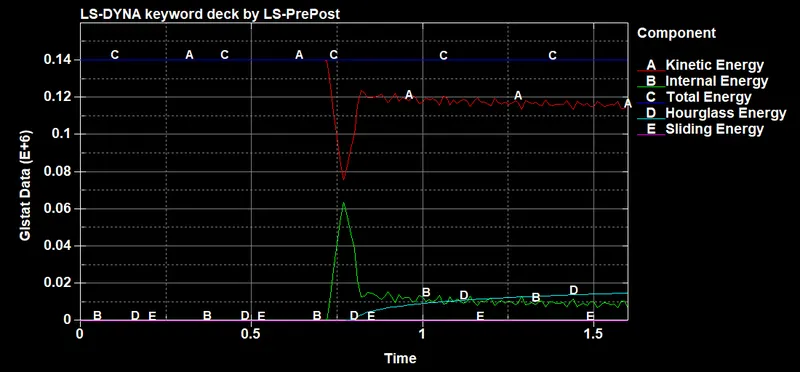
- From both the plots of Internal energy and Kinetic energy is similar in both graphs.The only noticable difference is in Hourglass energy in case of solid it is increasing after impact.
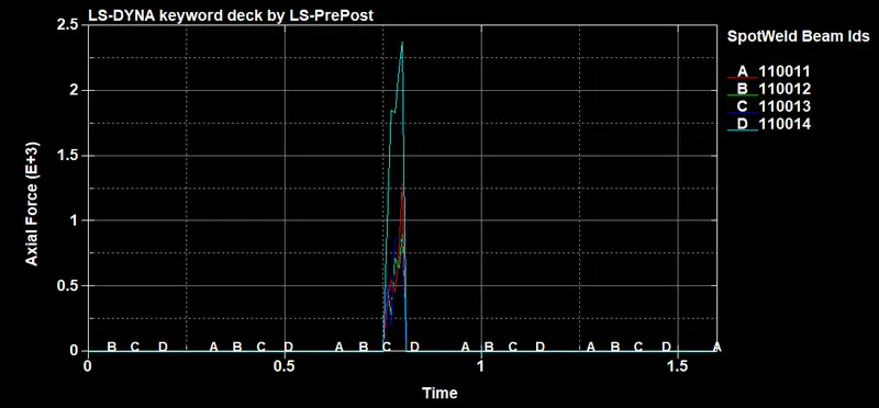
AXIAL FORCE-
FOR BEAM SPOTWELD:
FOR SOLID SPOTWELD:
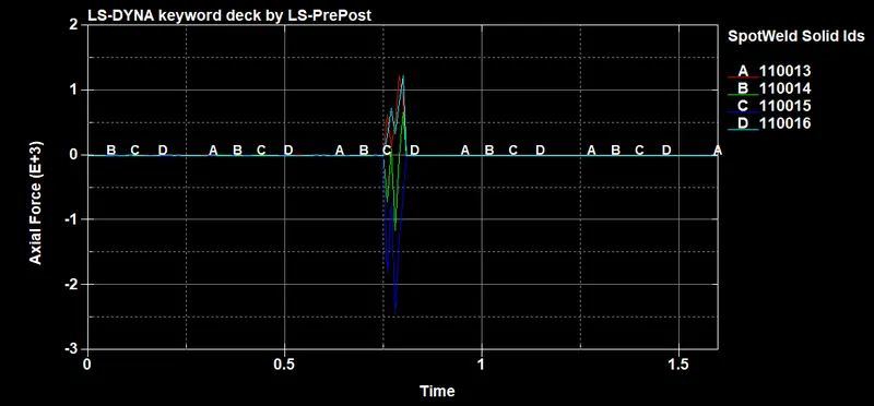
- We have noticed that solid weld is undergoing compression before failing at fail time 0.8ms, hence beam weld under tension load higher in magnitude than that of solid weld before they fail.
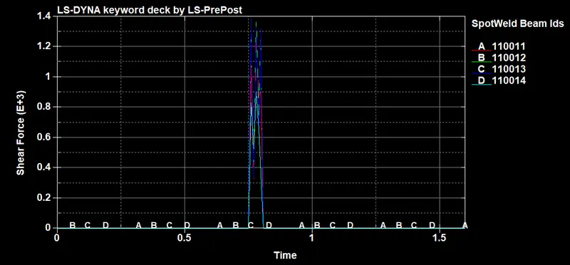
SHEAR FORCE:
FOR BEAM SPOTWELD-
FOR SOLID SPOTWELD-
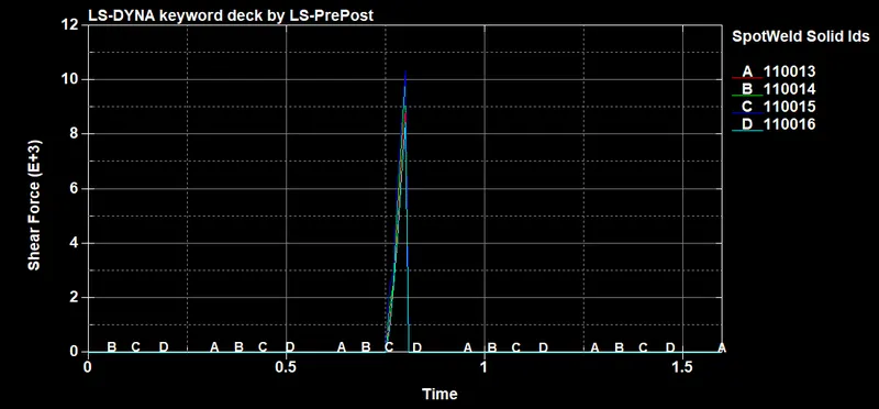
- Solid weld holds more shear force than that of beam weld before they fail.
CONCLUSION:
- Solid Weld and Beam wled modelling were simulated under the given condition and compared.
- Their is a noticable difference in the forces generated before failure in both the cases, when beam element is used for spotweld, the axial load is higher than normal which may lead to earlier failure if force based criteria used.
- And due to high axial load in the beam element localized stress is also higher. So here solid elements are more suitable for model as it has 4 nodes in contact and has better axial and shaer capabilities.