Week - 5 - Modelling Spotwelds
OBJECTIVE:
The objective of this project is to model spot welds to join two sheet metal components using beam elements in the first case and solid elements in the second and compare the axial and shear force experienced by the spot welds in both cases.
LS-DYNA SETUP :
CASE-1: BEAM SPOTWELD
- SPOTWELD ELEMENT GENERATION:
Spotwelds can be created between the two shell components by creating a beam element that is connected at both ends to the nodes of both the shell elements. This beam element then can be modeled using a spotweld material like MAT_100 and a beam section of type 9.
To create a beam element: Mesh -> EleGen -> Beam -> Two_Node_sets
This series of commands lets you select the required nodes in both the components that may act as the end nodes of the spot weld.
- PART - SECTION & MAT:
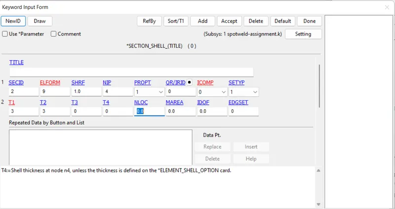
Shell Components: The shell components are modeled using a *SECTION_SHELL keyword with an Element formulation, ELFORM = 16, which is a- 'Fully integrated shell element' and a shell thickness of 1.5 mm
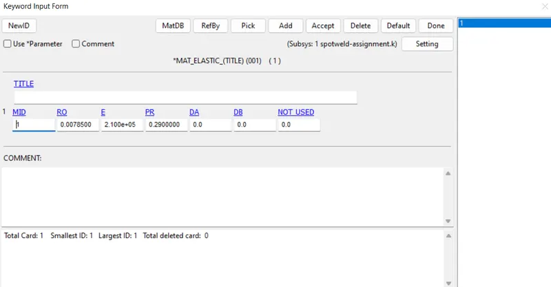
The Elastic material is used to model the shell section with the below parameters,
Spotweld: Beam Spot welds can be modeled using a beam section using the *SECTION_BEAM keyword and a*MAT_100_SPOTWELD material.
NOTE: While the MAT_100 material is consistent for modeling any type of spot welds, it poses few constraints like - "The material model applies to beam element type 9 and to solid element type 1".
Hence we can model the beam spot weld element using a *SECTION_BEAM of type 9 with a thickness/outer diameter of 3 mm and a 4x4 Gauss quadrature for increased integration points and more accuracy.
The MAT_100 card is specified as shown below,
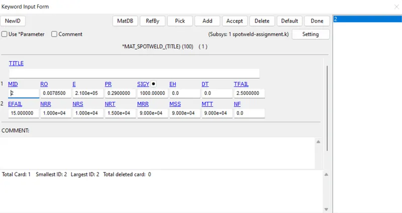
In the above card, TFAIL of 2.5 ms is specified, which is used to specify the time of failure of the beam spotweld element.
Similarly, other factors like Plastic strain, Force, and moment that could act as a threshold for the failure of the spotweld are specified in the below row.
- *INITIAL_VELOCITY
initial velocity card to be used to give some initial velocity to the model so that the model's kinetic energy will be absorbed by impact with a rigid wall
- CONTACT
This keyword is used to specify the Contact interface either between shell component and spot weld or self-contact of the shell elements with itself.
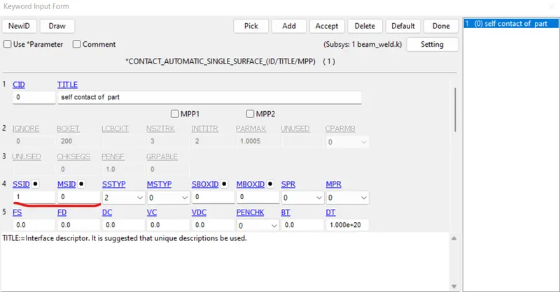
a. AUTOMATIC_SINGLE_SURFACE
This card can be used to specify contacts that could occur between the two shell components or the elements within.
This can be achieved by creating a SET_PARTS which contains both the top and bottom shell components and assigning it to SSID in the card while the SSTYP is set to 2.
NOTE: The master components MSID need not be assigned since the contact occurs within the elements within itself.
b. TIED_SHELL_EDGE_TO_SURFACE
While modeling spot welds with MAT_100, the following contacts could be used,
*CONTACT_TIED_SHELL_EDGE_TO_SURFACE
*CONTACT_SPOTWELD
*CONTACT_SPOTWELD_WITH_TORSION
The difference between them arises when factors like the type of spot weld element and forces involved varying.
In the case of a beam element connected to the nodes of the shell surfaces, we will use the*CONTACT_TIED_SHELL_EDGE_TO_SURFACE card. Here, the slave elements are the nodes of the beam element and the master elements are the shell parts (with SSTYP - 4, MSTYP - 2)
All contacts are frictionless since we are only concerned about the axial and shear forces in the spot welds.
5.CONTROL_TERMINATION
This keyword is used to specify the end time of the simulation which in this case is set to 5 ms
6. RIGIDWALL
the planar rigid wall is created as shown.
7. DATABASE
All output parameter requests are defined using this card.
a. BINARY_D3PLOT
This is the most important keyword where the output of the animation file is written (.d3plot).
For our simulation, we specify a time interval of 0.5, which represents that for each 0.5 ms the output data of the analysis is written onto the d3plot file.
b. ASCII_Option
Here the required output parameters that need to be computed are specified and written in a separate file. In our case, the following files are written for every time interval of 0.5 ms,
GLSTAT - Global Statistics involving KE, IE, hourglass energy, etc.
NODOUT - Nodal properties like displacement, acceleration, etc.
SLEOUT - Sliding interface energies
SECFORCE - Cross-sectional forces
SWFORCE - Spotweld Nodal Constraint Reaction Forces
ELOUT- element results
After Doing the similar analysis for Solid Weld:--
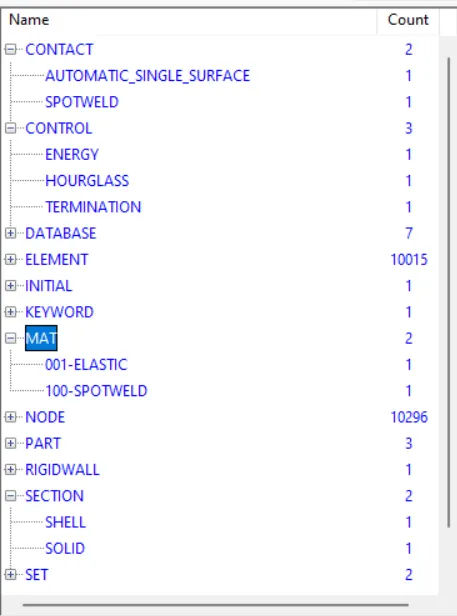
Results and comparison
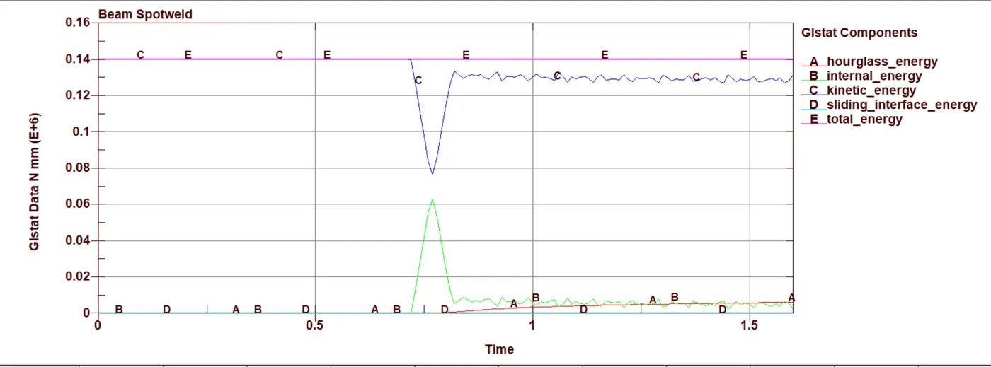
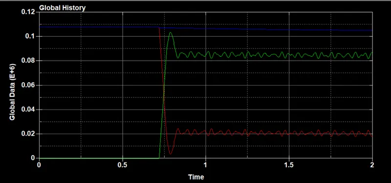
- Global energies
Beam Spotweld
Solid weld
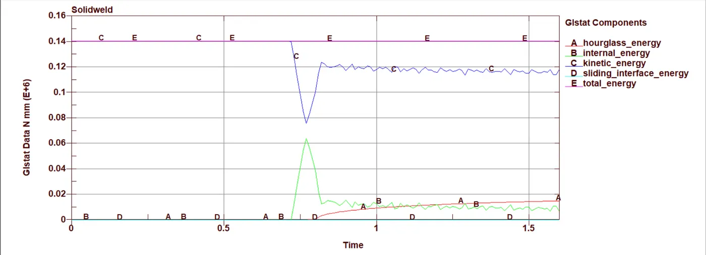
- From the global energy plots Internal energy and kinetic energy plots similar in both the beam and solid welds. But the hourglass energy in the case of the solid can be seen increasing after the impact.
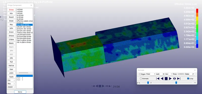
Von mises Stress
- At the time of impact, we can notice a comparatively higher von mises stress in the solid welds than the beam welds at the time of impact.
Beam weld
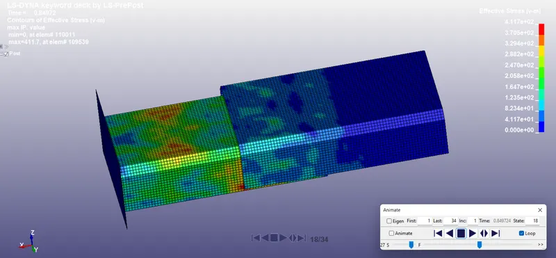
Solid weld:
Total Energy Comparision:
Beam Weld:
SolidWeld:
Conclusion
- Solid weld and beam weld modelling were simlulated
- We could notice difference in the forces generated before the failure.
- Most often when the actual material failure data is not available , user can try tfail for finding out the actual plastic strain, Axial force , shear force , moments which can cause the weld to fail by altering the parameters in the material card spotweld 100, this data can be later used for similiar welds in the future.