Week - 5 - Modelling Spotwelds
Modelling of Spotweld with Beam and Solid Elements in LS-DYNA
Aim: - To model spot welds between the given surfaces using Beam and Solid elements and compare the results.
Explanation: -
1] Spotwelds Using Beam Elements
- Create Spotwelds in the model - the model containing the upper and lower surfaces can be seen in LS-PrePost as shown below.
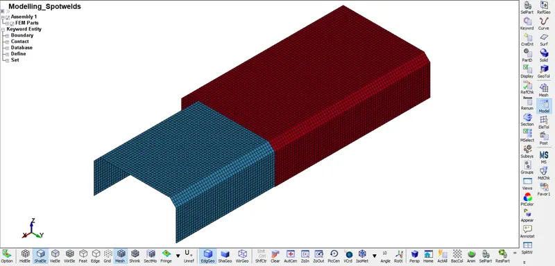
- Image 1: Given Model in LS-PrePost
- The Spotweld using beam element created using Mesh - EleGen - Beam By - Two_Node_Sets.
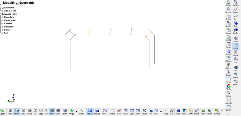
- Image 2: Beam Elements Created
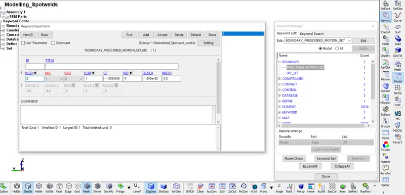
- Image 3: Boundary Prescribed motion set card
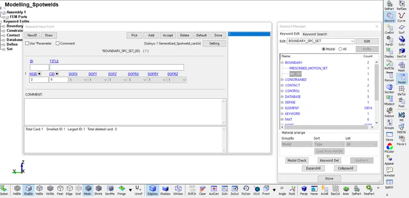
- Image 4: Boundary SPC Set
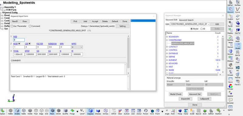
- Image 5: Constrained generalized weld spot
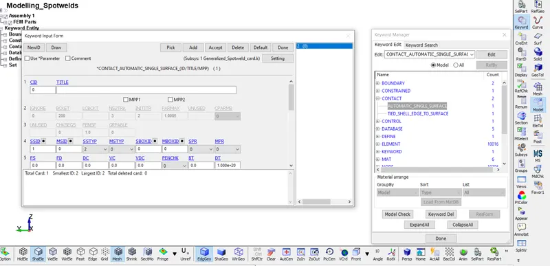
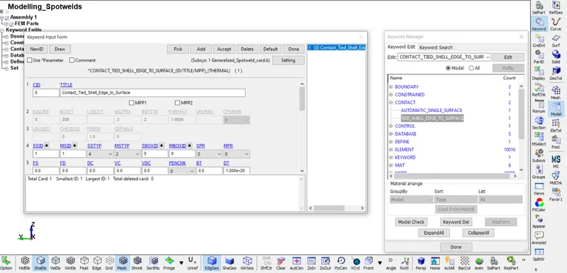
- Image 6: Contact defined
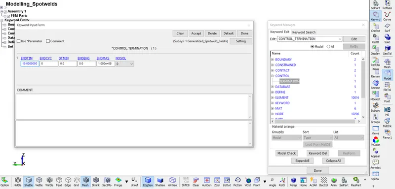
- Image 7: Control parameters
- Image 8: Curve Defined
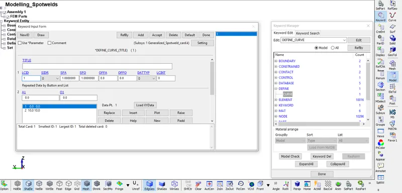
- Image 9: Beam Element Created
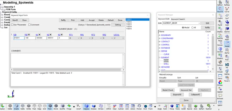
- Image 10: Element
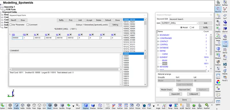
- Image 11: Shell Element Created
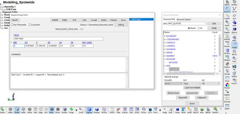
- Image 12: Elastic Material Defined
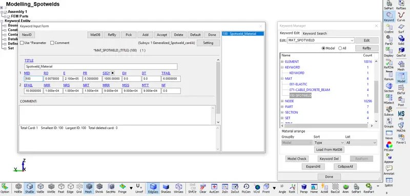
- Image 13: Mat Spotweld
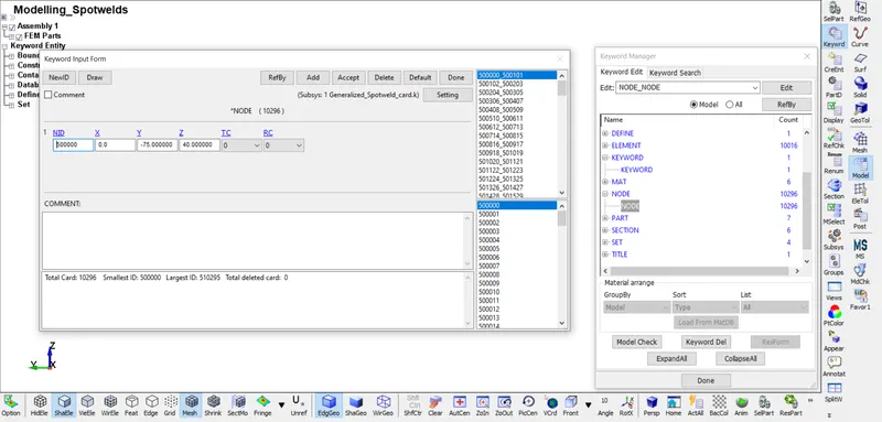
- Image 14: Node Creation
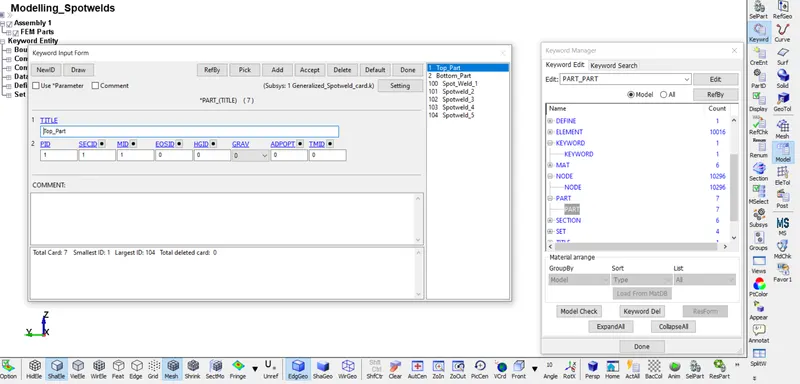
- Image 15: Part Creation
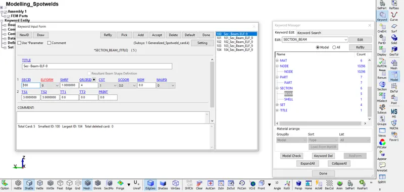
- Image 16: Section Beam Creation
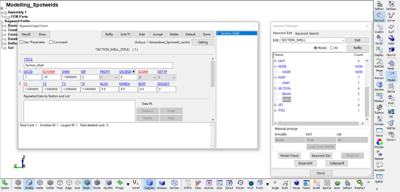
- Image 17: Section Shell Creation
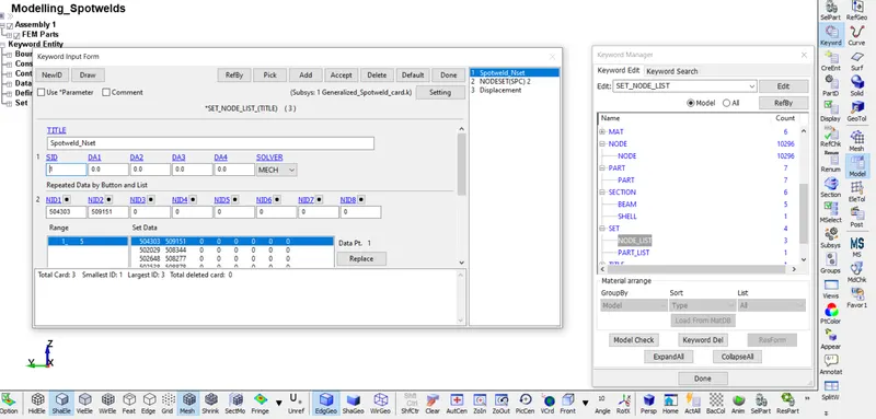
- Image 18: Set Node Creation
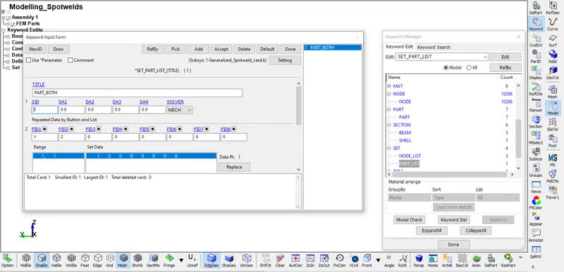
- Image 19: Setting Part List
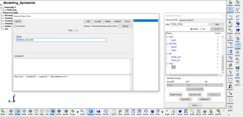
- Image 20: Inserting Title Name
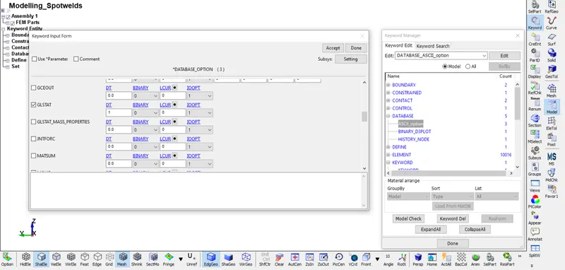
- Image 21: Inserting Database
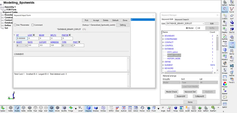
- Image 22: Binary D3PLOT
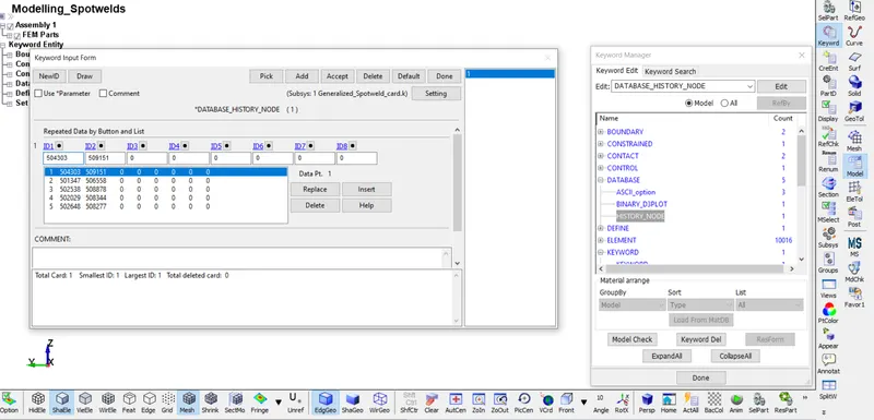
- Image 23: Database History Node
2] Spotwelds Using Solid Elements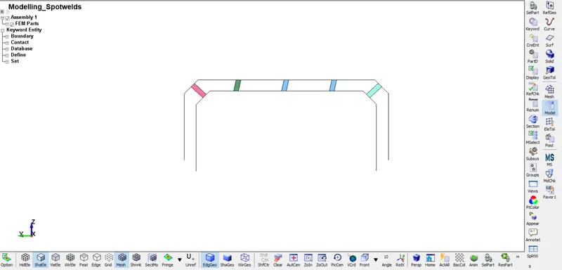
- Image 24: Solid Spotweld Created
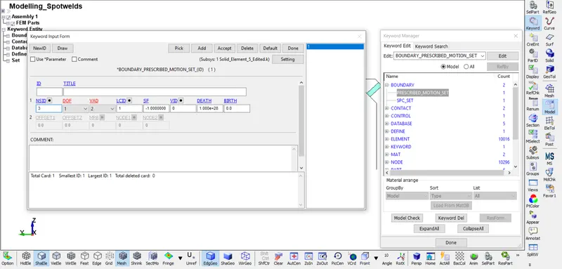
- Image 25: Boundary Condition Setting
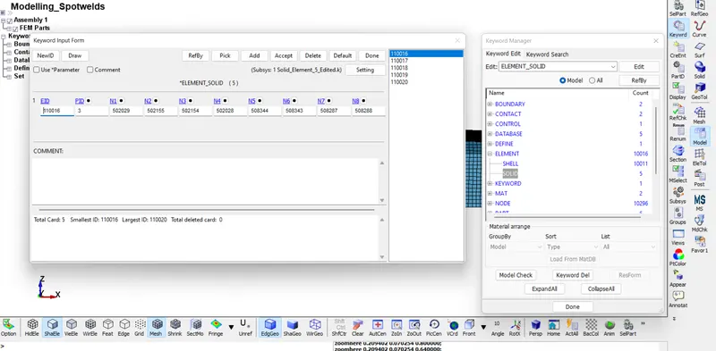
- Image 26: Solid Element Creation
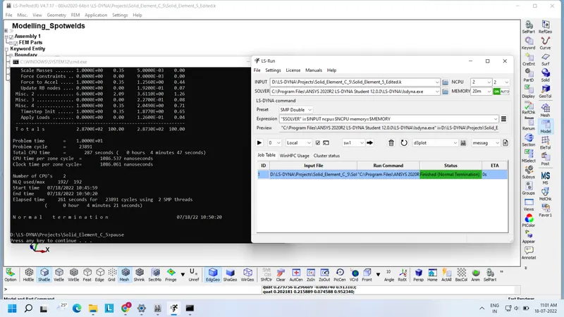
- Image 27: Normal Termination
- Post-Processing=
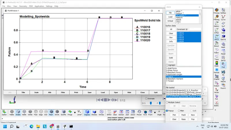
- Image 28: Failure analysis of Solid Spot welding
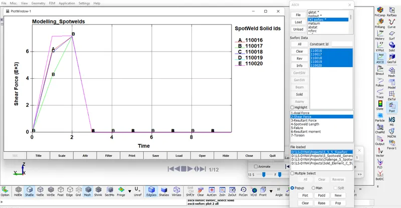
- Image 29: Shear Force for Solid Spotweld
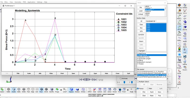
- Image 30: A shear force for Beam Element
Conclusion: Shear force graph plotted for both Beam and Solid Elements. A Solid Spot weld has high strength compared to Beam Element Because the beam element has only 2 nodes to hold the impact compared to the solid element which has 8 nodes to hold the spot weld.