Tool Test-2
Meshing the Intake Manifold Component of an Engine using Tetra Elements in ANSA
Objective = The main objective of this project is to mesh the Automotive Engine Intake Manifold Component using Tetra elements as per the quality criteria shown below.
Quality Criteria: Quality Criteria shown in table no. 1.
Table 1. Quality Criteria Table.
| Sr. No. | Quality Criteria | Value |
| 1. | Target / Average Length | 3 |
| 2. | Minimum Length | 1 |
| 3. | Maximum Length | 5 |
| 4. | Tet collapse | 0.2 |
Procedure:
- Import Cad Geometry = File -Open -Select Geometry.
- The given CAD geometry imported in ANSA workbench and orientation checked.
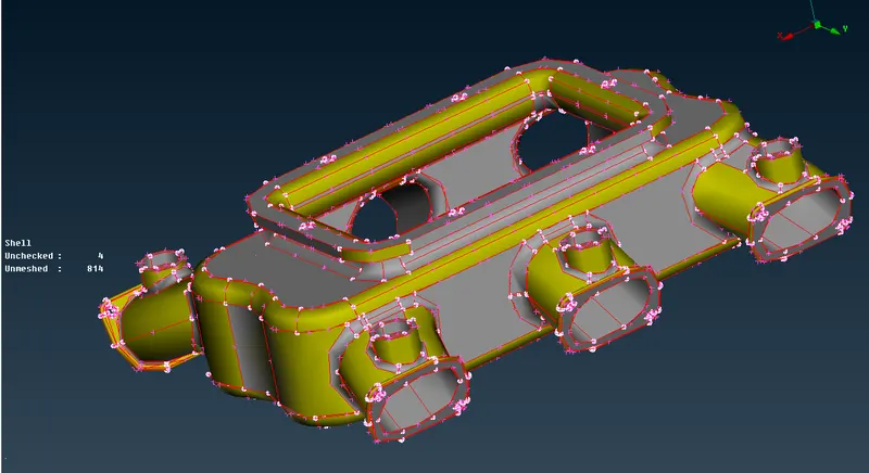
- Image 1: Imported CAD Model (Intake Manifold Component)
- Geometry Clean-UP = Tools -Checks -Geometry. Errors are resolved automatically by using fix command in geometry.
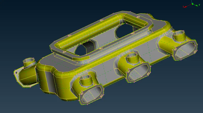
- Image 2: Before Geometry Clean-up
- Topo - Faces - Topo Command used to clear issues with the orientation.
- All geometrical errors are cleared using auto FIX option.
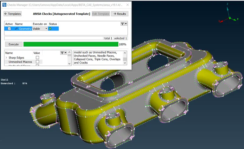
- Image 3: After Geometry Clean-up
- Thickness Measurement : Thickness measured using Utilities - Measure. As this is a complex Component it has varying thickness though out the modal as shown in Image 4.
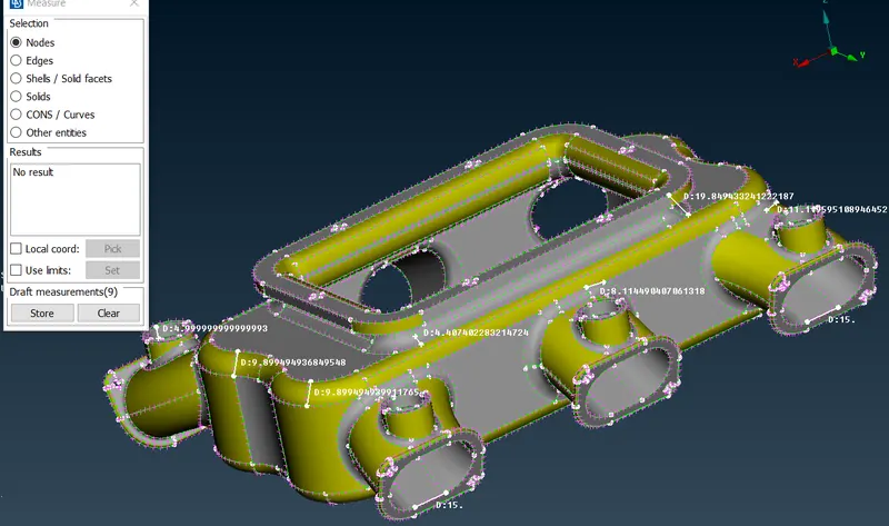
- Image 4: Thickness Measurements
- The resolution of CONS improved using Mesh - Length - Perimeters - Macros.
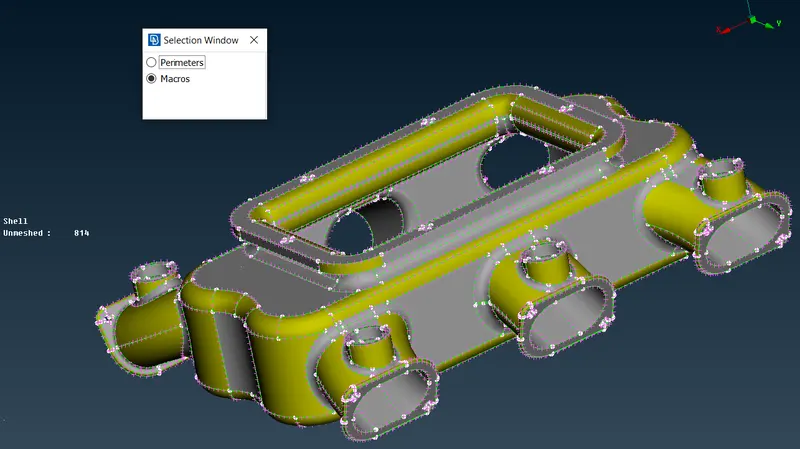
- Image 5: Cons Resolutions
- Mesh Generation : The perimeter elemental length is set using Mesh - Perimeter - Length option.
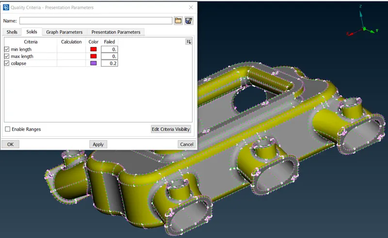
- Image 6: Quality Criteria-Presentation Parameters
- The Quality Criteria Shown in table no. 1 are applied to the model using utilities - Quality Criteria
- Mesh Parameters are applied using Utilities - Mesh Parameters.
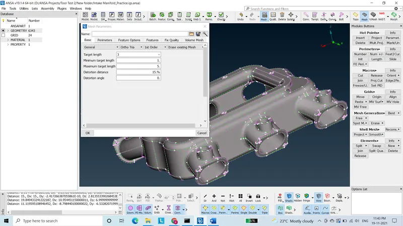
- Image 7: Mesh Parameters
- F11 Function Key is a shortcut for Quality Criteria - Presentation Parameters.
- Mesh is done using Mesh - Mesh Generation - Spot Mesh.
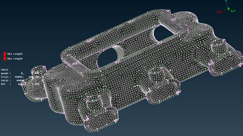
- Image 8: Meshed Component
- For better results of mesh Mesh - Shell Mesh - Reconstruction used.
- Volume mesh is generated by using Volume Mesh - Unstructured Mesh - Tetra Rapid.
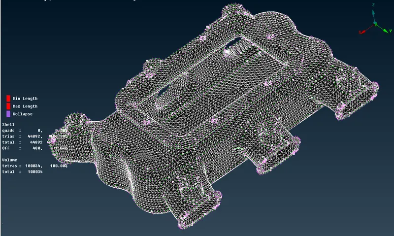
- Image 9: Volume Mesh Component
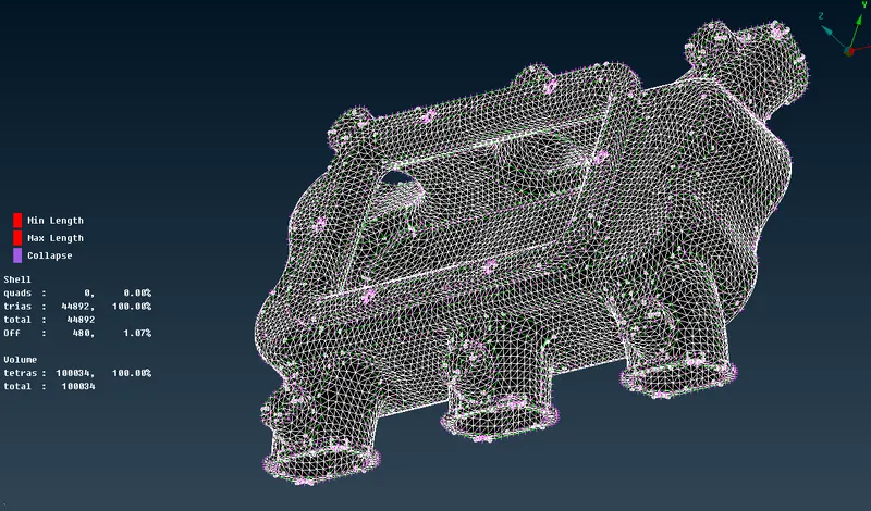
- Image 10: Improved Meshed Quality Component
- Meshed Quality Improved by using Volume Mesh - Improve - Fix Quality.
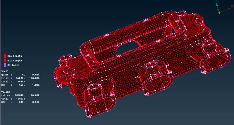
- Image 11: Tet collapse Quality Checking
- Result : The given Intake Manifold of an Engine Component is Meshed as per the Quality Criteria.
- Conclusion: From this challenge I learned about CAD model import, Geometry clean-up, New PID creation for Volume Component, Setting up Quality Criteria, Mesh Generation using Tetra elements and Ortho Tria, Reconstruction of mesh as per given quality criteria to check Tet collapse, Volume Meshing, Surface Meshing.