Week - 5 - Modelling Spotwelds
SpotWelds Modelling
OBJECTIVE:-
To create spot-weld Beam and solid beam elements on given plate assembly separately. Also, perform the crash analysis for both and compare the output results.
INTRODUCTION:-
Spot welding is one of the oldest welding processes. It is used in a wide range of industries but notably for the assembly of sheet steel vehicle bodies. This is a type of resistance welding where the spot welds are made at regular intervals on overlapping sheets of metal. Spot welding is primarily used for joining parts that are normally up to 3 mm in thickness. Spot Welding is used to weld various sheet metal products, through a process in which contacting metal surface points are joined by the heat obtained from resistance to electric current.
PROCEDURE:-
Import the Model:-
Open the LS Prepost software and import the keyword file (.k file).
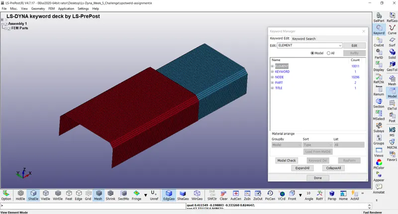
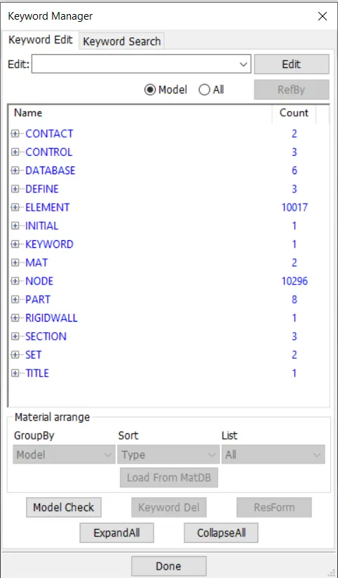
Here we can see that there are 5 keywords already defined in the .k file for basic model and now we have to define some additional keywords in order to simulate the crash of model with spotwelds having beam elements.
Defining Sections for Plates:-
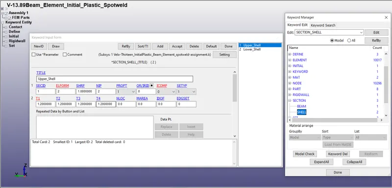
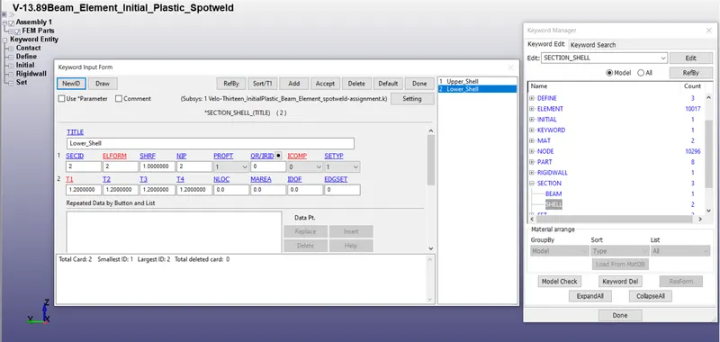
Total 2 Sections are defined by going to SECTION_SHELL, first one is for upper plate with SECID=1 and the other one is for lower plate with SECID=2 having 1.2mm thickness. All the other values are taken default.
- SECID: Section ID. SECID is referenced on the *PART card. A unique Number or label must be specified.
- ELFORM: Element formulation options.
- SHRF: Shear correction factor which scales the transverse shear stress.= 1
- NIP: Number of through-thickness integration points = 2
- T1: Shell thickness =1.2 mm
Defining Load Curve for Plate Material:-
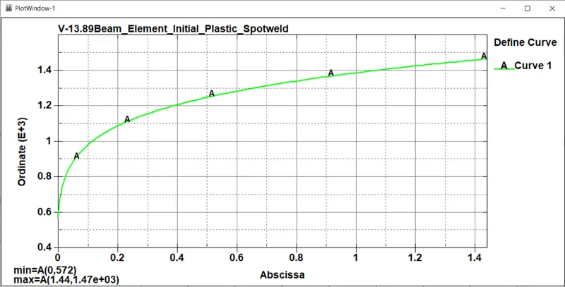
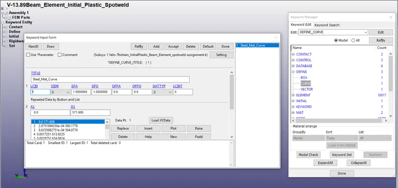
We have to define the curve data for plate material and we can load the curve data from a .csv file. Go to Load XYData and locate the .csv file and then click on accept. we can also plot this curve by clicking on Plot. Generally .csv is a comma seperated value file which have curve plot data between EPS and ES in the form of numerical values.
Defining Materials for Plates:-
Though we can take any material but for this simulatation, but here we have taken Steel as plate material and it is a linear plastic material since linear plastic material is used so 024-PIECEWISE_LINEAR_PLASTICITY material card has to be defined we can also go for MAT_ELASTIC also which is used for defining elastic marerials. *MAT_024* is the piecewise Linear plasticity material card which is suitable for robust materials of linear plasticity also suitable for elastoplastic materials.
- MID: Material identification. A unique number or label not exceeding 8 Characters must be specified.
- RO: Mass density.
- E: Young’s modulus.
- PR: Poisson’s ratio.
- SIGY: Yield Stress
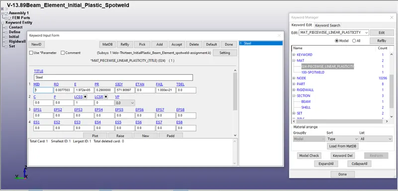
If we define Tangent Modulus (ETAN) for the material then we do not need to input Load Curve ID (LCSS) but since we have not given the ETAN value so we have to define LCSS and give the already defined material curve as input in LCSS.
Defining Contacts for Shells:-
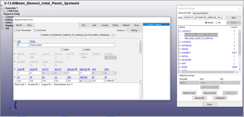
AUTOMATIC_SURFACE_TO_SURFACE contact card is used to defined contact between the plates to encounter the case if welds get damaged because in this case both the plates can come in contact.
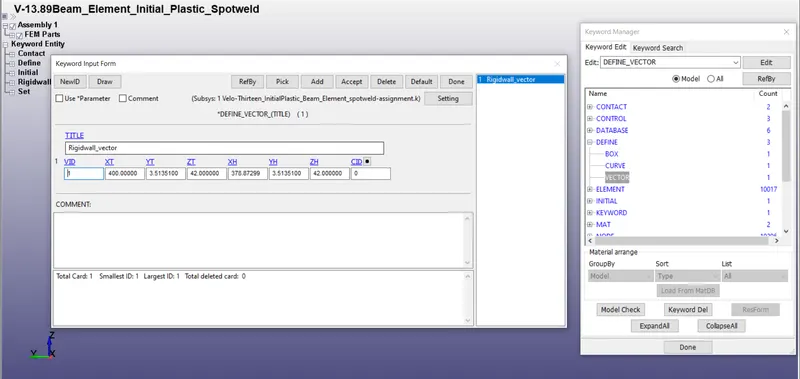
Defining Vector:-
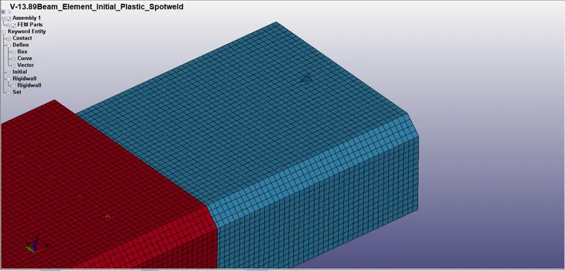
A vector is created to define the normal direction of the rigidwall. This is important because the vector normal of rigidwall should be facing the coming plate otherwise the rigidwall would not detect the plate nodes, hitting the rigidwall and also this is the reason that we do not need to define a seperate contact for plate and rigidwall because defining vector direction of rigidwall normal is enough in this case for rigidwall to detect the plate.
Defining Rigidwall:-
Rigid wall definitions have been divided into two separate sections, PLANAR and GEOMETRIC. Planar walls can be either stationary or moving in translational motion with mass and initial velocity. The planar wall can be either finite or infinite. Geometric walls can be planar as well as have the geometric shapes, such as rectangular prism, cylindrical prism and sphere.
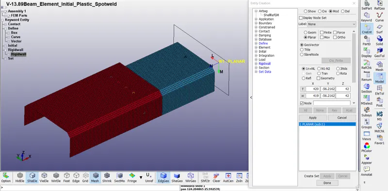
Rigidwall can be defined by going to create entity option using any of the node present at the edge of the plate and then it can be translated using Tran option to required distance. The distance between lower plate and rigidwall is 20mm.
Setting Up SPOT WELDs-
1) FOR BEAM ELEMENT
Creating Beam Elements:-
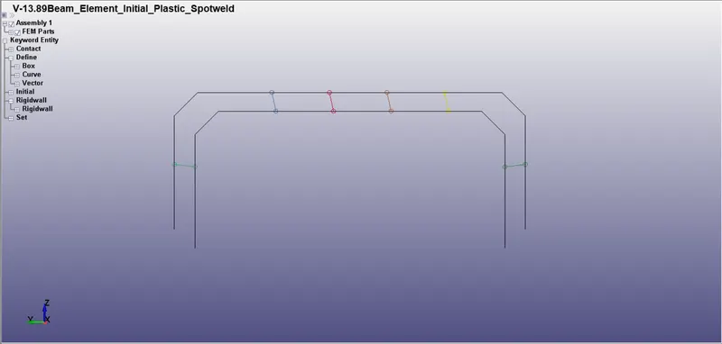
The spot weld modeled using beam element is created by following the procedure given.
Mesh > Element Generation > Beam > Give Part ID > Select Beam by Two_Node_Sets > Pick Node set 1 & 2 (pick the desired nodes from the bottom and top sheet metal) > Create > Accept > Done.
Now this beam element acts as a spot weld.
Here the fact is that automatically a Section card (*SECTION_BEAM) and the Material card (*MAT_CABLE_DISCRETE_BEAM) are created and we need to delete these cards and assign our required material and section cards for the Beam Elements created as spot weld.
2) FOR SOLID ELEMENT
Creating Solid Elements:-
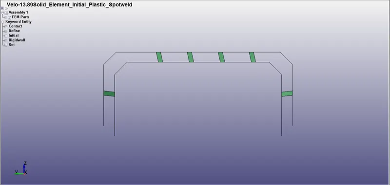
The spotweld modeled using solid element is created by following the procedure given.
Element Tools > Element Editing > Create > Type - Hexa > Pick four desired nodes from the bottom and top sheet metal > Accept > Done.
Now this solid element act as a spot weld.
Defining Material Cards for SPOT WELD -
For the beam element and solid element, the material card is assigned as the *MAT_100 which is MAT_SPOTWELD card that is especially for the spot weld material. We have given terms like SIGY, TFAIL, EFAIL, NRR, NRS, NRT as a higher value to ensure that weld elements don't fail.
- MID: Material identification. A unique number or label not exceeding 8 characters must be specified.
- RO: Mass density
- E: Young’s modulus.
- PR: Poisson’s ratio
- SIGY: Initial yield stress
- TFAIL: Failure time if nonzero. If zero this option is ignored.
- EFAIL: Effective plastic strain in weld material at failure
- NRR: Axial force resultant at failure.
- NRS: Shear Force resultant at failure
- NRT: Force resultant at failure
- MRR: Torsional moment resultant at failure.
- MSS: Moment resultant at failure
- MTT: Moment resultant at failure.
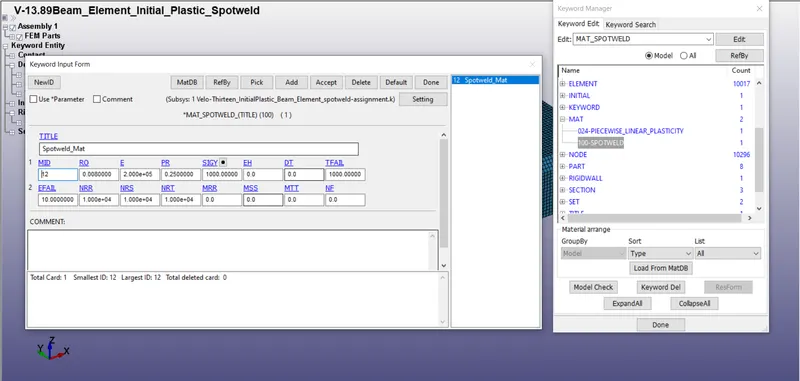
Defining Section Cards for SPOT WELD -
1) FOR BEAM ELEMENT
For the beam element, the section property is assigned by using the *SECTION_BEAM card. It is important to assign element formulation (ELFORM) as 9 because the *MAT_100 spot weld material model only applies for ELFORM 9 formulation in the case of the beam element. The cross-section type is selected as tubular since the default cross-section (rectangular) gives zero cross-section area during the simulation and the beam thickness at both ends is given as 3mm.
- SECID: Section ID. SECID is referenced on the *PART card. A unique Number or label must be specified.
- ELFORM: Element formulation options.= 9 spotweld beam
- SHRF: Shear correction factor which scales the transverse shear stress.= 1
- TS: Beam thickness or Outer diameter (Thickness defined on the *ELEMENT_ BEAM_THICKNESS card overrides the definition given here)
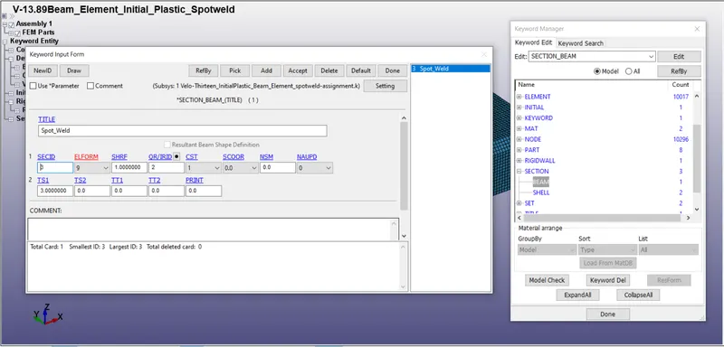
2) FOR SOLID ELEMENT
For the solid element, the section property is assigned by using the *SECTION_SOLID card. It is important to assign element formulation (ELFORM) as 1 because the *MAT_100 spot weld material model only applies for ELFORM 1 formulation in the case of the solid element.
- SECID: Section ID. SECID is referenced on the *PART card. A unique Number or label must be specified.
- ELFORM: Element formulation options.= 1 solid element.
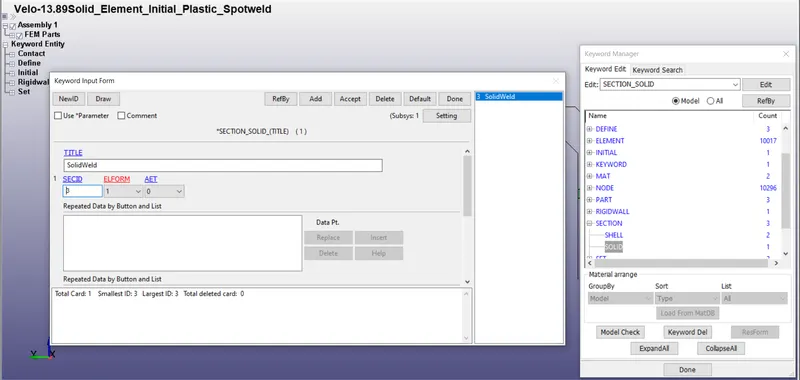
Defining Contacts for SPOT WELD -
1) FOR BEAM ELEMENT
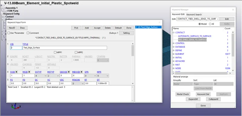
Here for the beam element, the contact type to be used is *CONTACT_TIED_SHELL_EDGE_TO_SURFACE card and the Master Set ID will be Part Set ID and the Slave Set ID will be Node Set ID haing nodes of beam elements as a set of nodes.
->Steps used for creating Part Set and Node Set are mentioned below.
Entity Create > SetData > *SET_NODE > Pick the nodes > Apply.
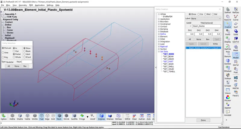
For defining the Master set select both the metal sheet parts and the steps is mentioned below.
Entity Create > SetData > *SET_PART > Pick the part > Apply.
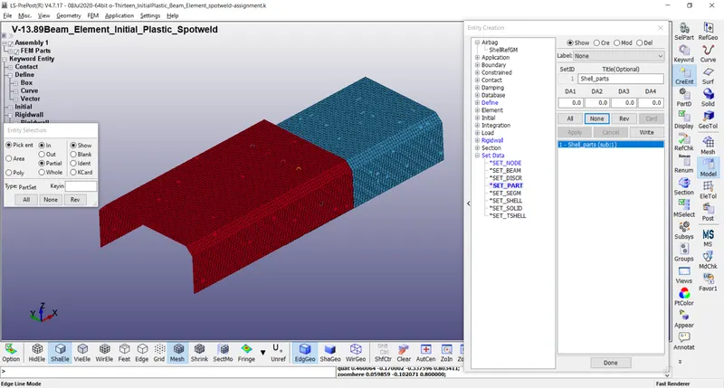
So assign both the Slave-Set and the Master-Set as created by the above technique to the contact card. *CONTACT_TIED_SHELL_EDGE_TO_SURFACE card.
Slave-type - Node Set ID
Master-type - Part Set ID
2) FOR SOLID ELEMENT
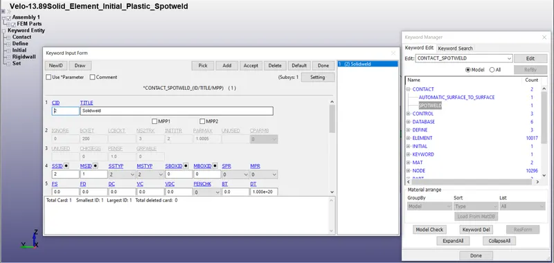
Here for the solid element, the contact type to be used is the *CONTACT_SPOTWELD card and the Master Set ID will be Part Set ID, and the Slave Set ID will be nodes of solid weld element.
->Steps used for creating Part Set are mentioned below.
For defining the Master set select both the metal sheet parts and to define the Slave set select the solid weld.
Entity Create > SetData > *SET_PART > Pick the part > Apply.
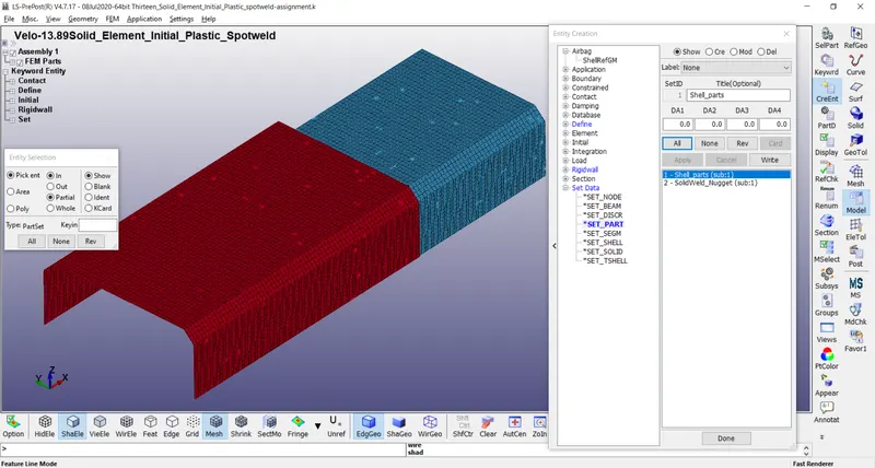
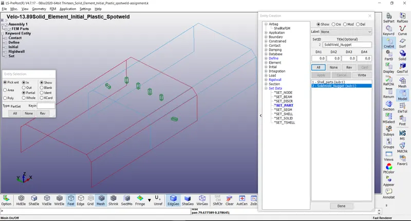
So assign both the Slave-Set and the Master-Set as created by the above technique to the contact card. *CONTACT_SPOTWELD card.
Slave-type - Node Set ID
Master-type - Part Set ID
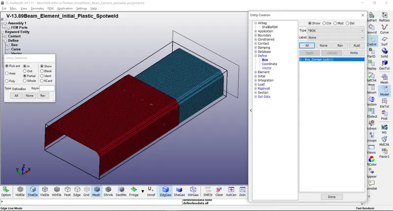
Defining Box for Initial Velocity:-
A box is basically created containing all the three parts which are bot the shells and spotwelds in order to give them an initial velocity simultaneously. Go to Create Entity > Define > Box and create a box.
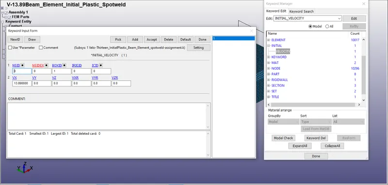
Defining Initial Velocity:-
Initial velocity of 13.89mm/ms is given to the box as it can be seen in the image below.
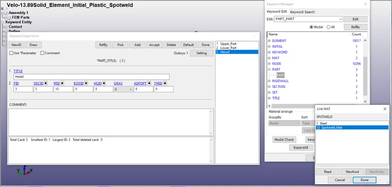
Assigning Materials and Sections to Parts:-
Now we can assign materials and sections for plate shells and spotwelds.
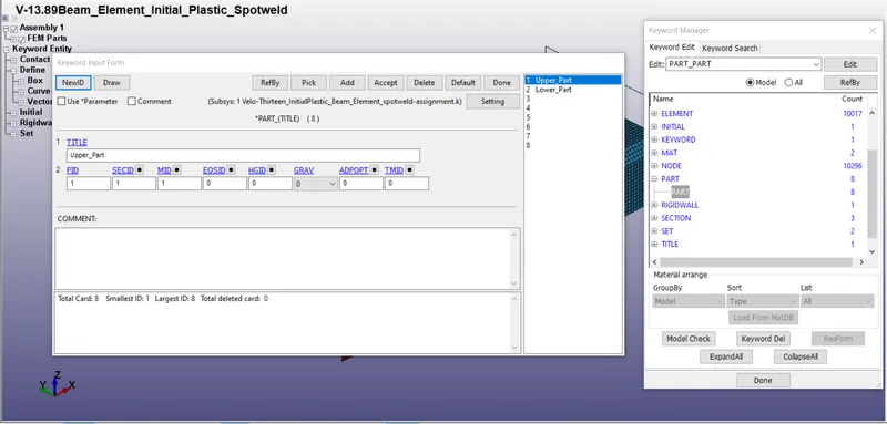
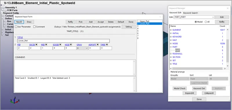
1) FOR BEAM ELEMENT
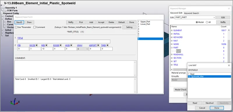
2) FOR SOLID ELEMENT
Defining Control Keyword:-
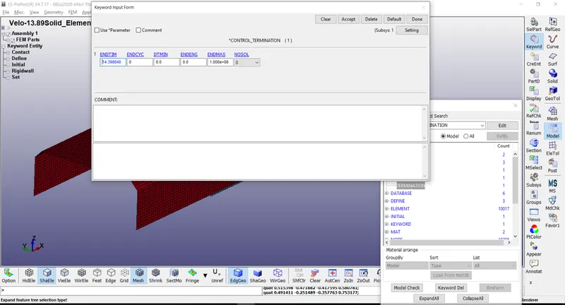
CONTROL_TERMINATION:-
Control_Termination card is defined for at what time the simulation should end or the end time of the simulation Which is called Termination Time and it is set to 14.398840ms for this simulation.
- ENDTIM: It is the time at which the simulation ends
Defining Database:-
Database creation is defined for output request as per requirement. Simulation is performed to get required outputs and these outputs can be requested from the software to provide. There are some keywords that need to get defined under DATABASE KEYWORD in order to get outputs in the form of graphical data.
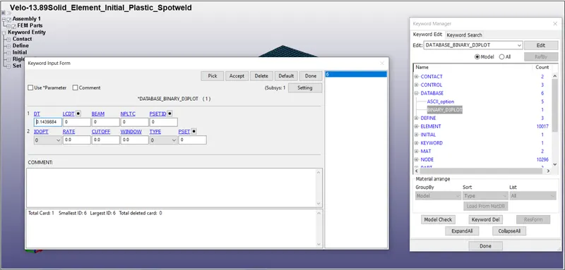
DATABASE_BINARY_D3PLOT:-
Defining this card is must because when this card is defined, it generates d3plot file as output after running the simulation and this d3plot file is the main simulation file which shows the simulation animation when played in LS-PrePost. BINARY_D3PLOT is defined as the frequency at which the data should be written in animation file which is to be created and is set to 0.14398840ms for this simulation.
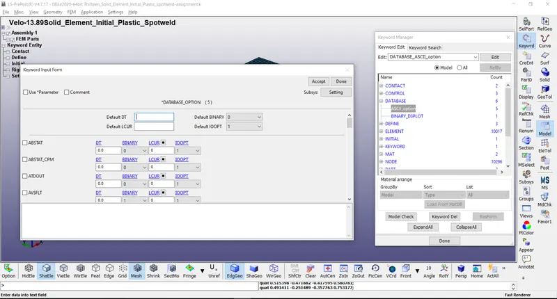
DATABASE_ASCII:-
ASCII option keyword is defined for the output request of data in ASCII format, The following keywords are Activated in this simulation. The time step value of 0.14398840ms is given to DATABASE_ASCII option.
- GLSTAT: Global Data
- MATSUM: Material Energies
- SWFORC: Spotweld Nodal Constraint Reaction Forces
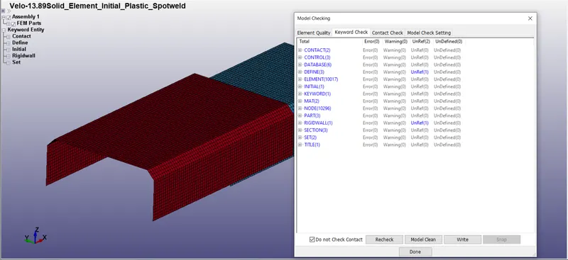
The keyword file created is checked for errors using the option keyword manager > model check. The keyword file is saved using ‘.k’ extension and is made to run in the LS-Run solver.
It should show Normal Termination message after completion of run as shown in below image otherwise if it shows Error message then that should be encountered by the engineer.
Now the solver deck setup is complete and ready to run the Analysis.
RESULTS:-
Simulation:-
The D3plot output File is opened in LS-PrePost using option File > open > LS-Dyna binary plot.
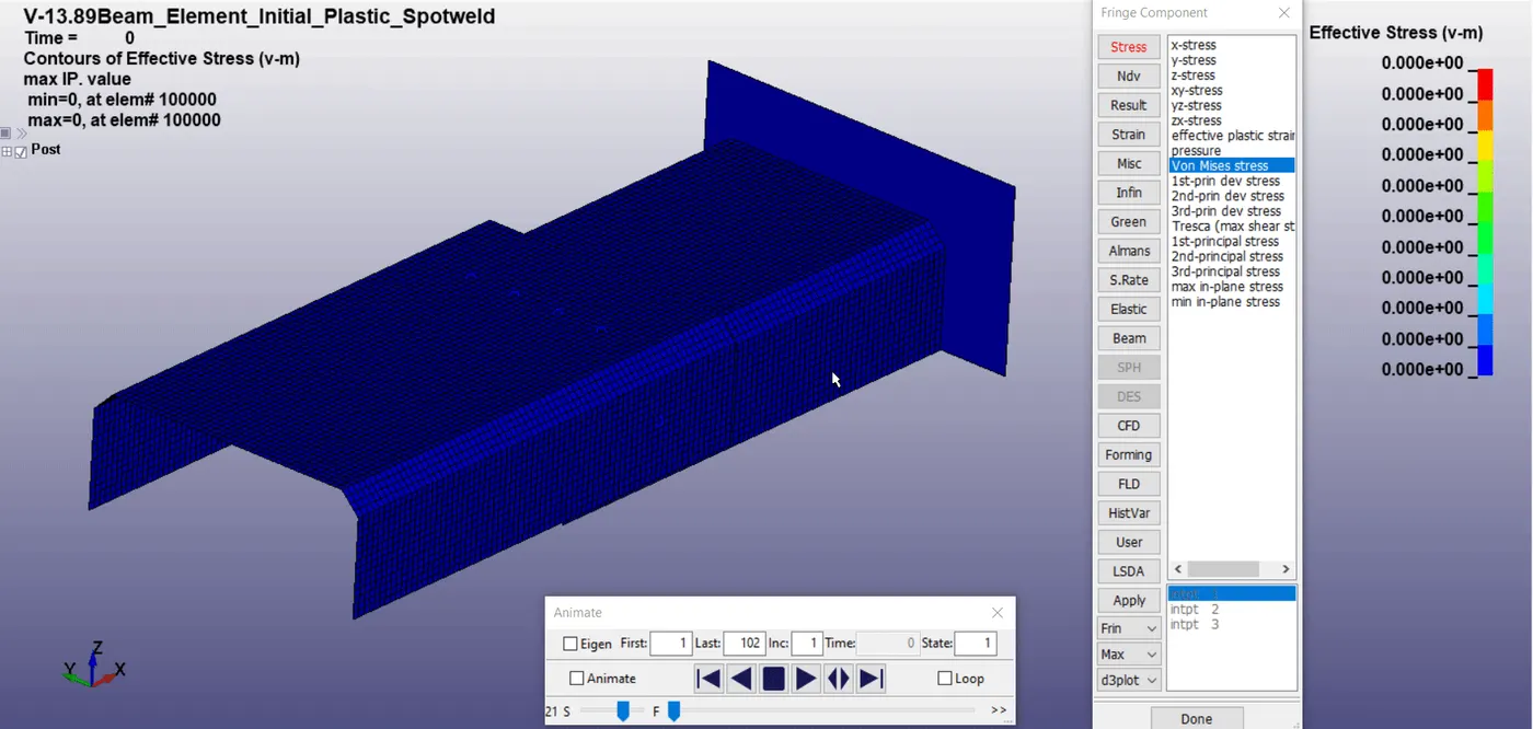
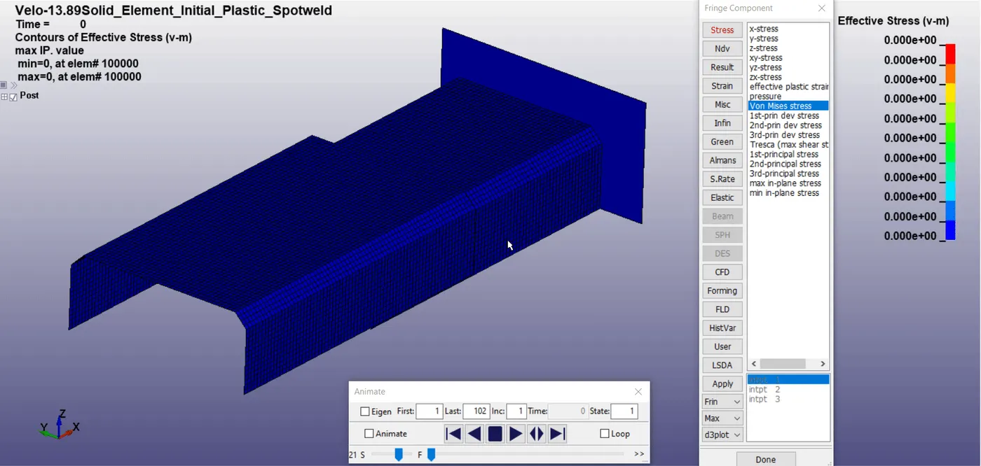
The animation of Von-Mises stress for 1.2 mm thick crash box is as shown below.
For Beam Element:-
For Solid Element:-
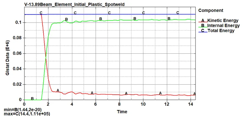
Energies Plot Comparision:-
Beam Element Spotweld -
Solid Element Spotweld -
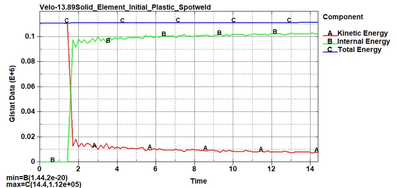
It can be seen that when the plates hits the rigid wall, there is a reduction in the kinetic energy of the plates while there is an increment of the internal energy of the wall and after that both energies become constant. Value of the Total Energy is constant throughout this validates the principle of conservation of energy which states that energy can neither be created nor destroyed but can be converted from one form of energy to another.
Various Force Comparision:-
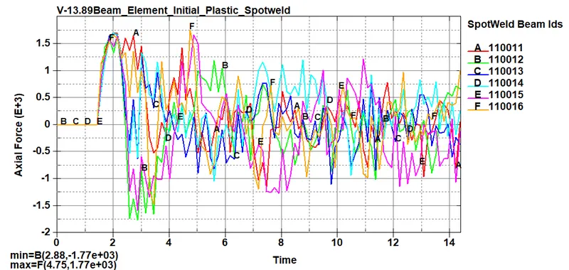
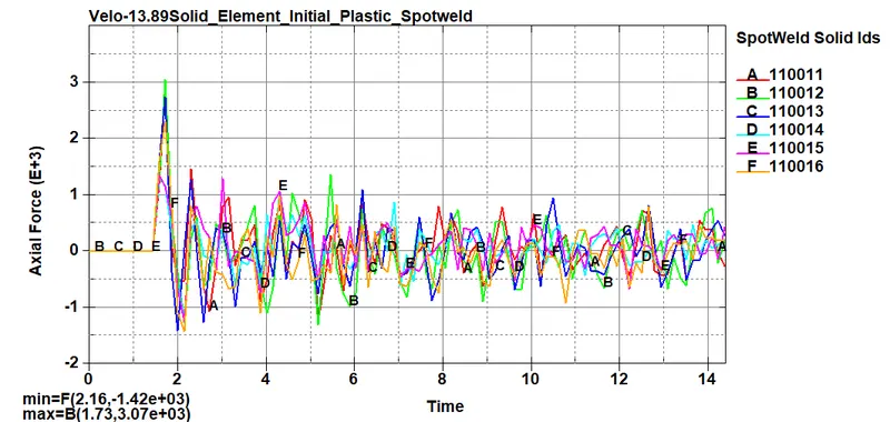
Axial Force Comparision:-
Beam Element Spotweld -
Force (gm.mm/ms^2) Vs Time (ms)
Solid Element Spotweld -
Force (gm.mm/ms^2) Vs Time (ms)
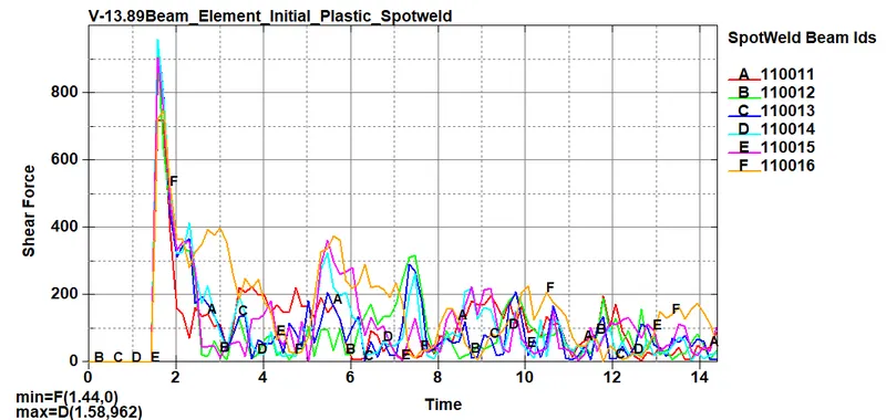
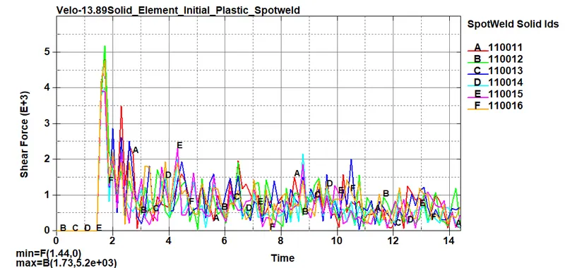
Shear Force Comparision:-
Beam Element Spotweld -
Force (gm.mm/ms^2) Vs Time (ms)
Solid Element Spotweld -
Force (gm.mm/ms^2) Vs Time (ms)
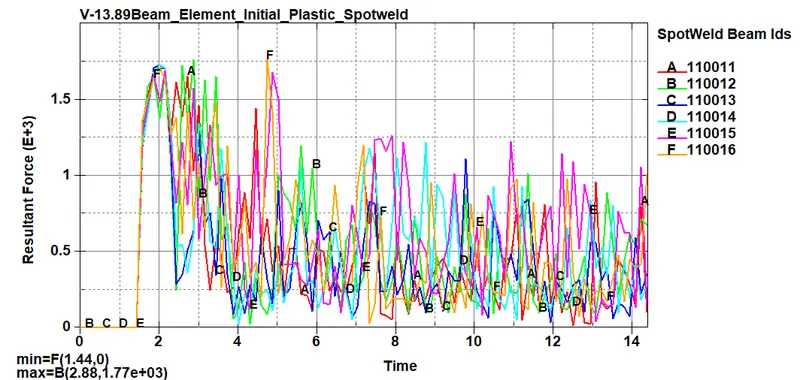
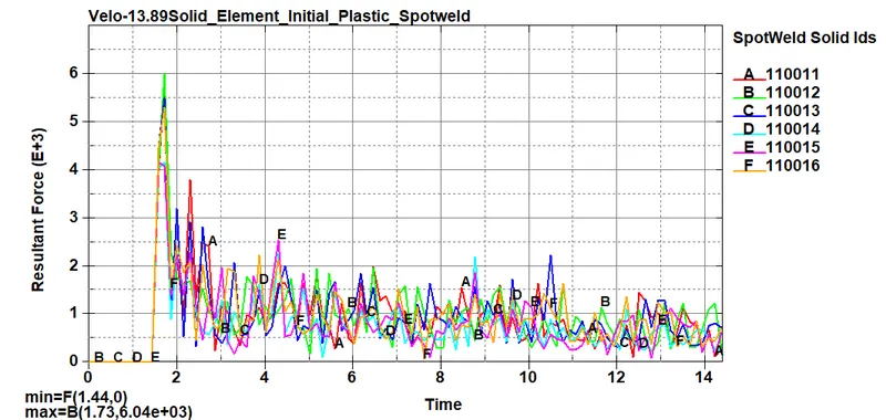
Resultant Force Comparision:-
Beam Element Spotweld -
Force (gm.mm/ms^2) Vs Time (ms)
Solid Element Spotweld -
Force (gm.mm/ms^2) Vs Time (ms)
CONCLUSION:-
- Simulation keyword preparation is done according to the given requirement.
- Animation and the simulation is run using LS-Run without any error termination
- Simulation is done for both beam and Solid element and analyzed the results.
- Plotted graphs for output energies of spot-welds created using Beam Elements and Solid Elements.