Week - 5 - Modelling Spotwelds
Simulation File: https://drive.google.com/drive/folders/1cTPdaeR5OEla0siNwXq5MMYrsA6MJwR9?usp=sharing
Aim: Perform spot weld test simulation using beam and solid element as spot welds
Objective:
- To create crash simulation by connecting the two brackets using beam and solid material represented as spot welds
- Compare the results in both iterations
Case 1: Beam Element
Material and Section:
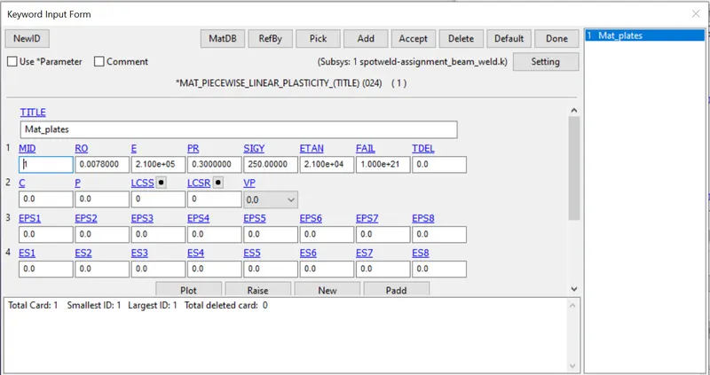
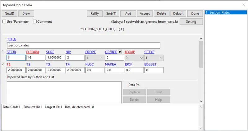
- There are two parts in the model, upper plate and lower plate. Create a material card and section card and assign these characteristics to the part keyword
- For both plates, shell element is considered with element formulation of 16 which is fully integrated shell elements for high accuracy.
- Material>steel
Create Spotweld:
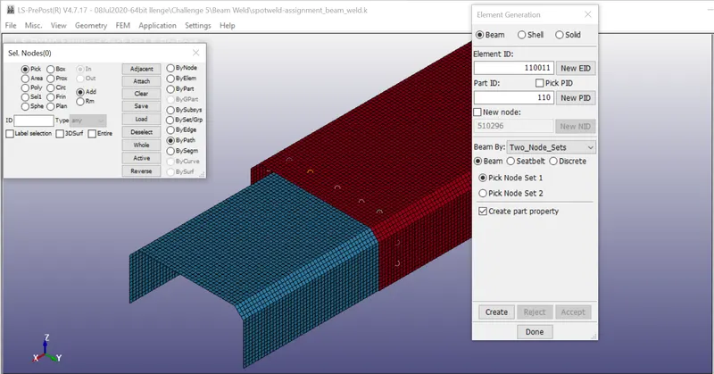
- In iteration1, spot welds are represented as Beam elements. The Nine spot welds are created using Mesh>Element generation>Beam>Select two nodes and accept
Material and Section Spot Weld
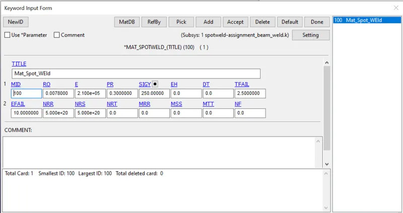
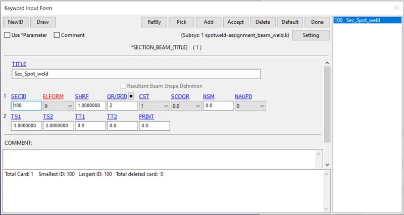
- MAT_SPOTWELD is material for spot weld beam elements
- SECTION_BEAM is a section card for spot weld beam elements
- In the material card, the TFAIL value is 3ms which is half of the TERMINATION time as it is a requirement of a simulation study to fail the spot weld during simulation
- Later, assign section and material to the BEAM parts in PART keyword
Contacts:
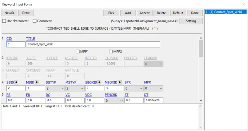
- TIED_SHELL_EDGE_TO_SURFACE- In this contact beam element is treated as a slave and two bracket shell elements are considered as Master
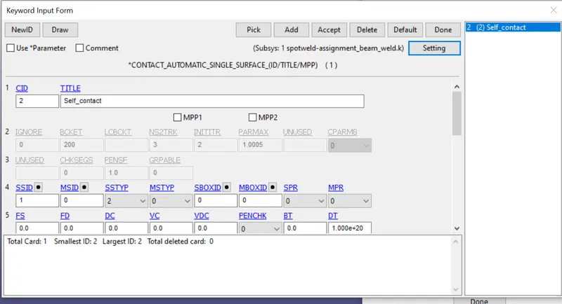
- AUTOMATIC_SINGLE_SURFACE- This contact is used to avoid self penetration of two brackets. In this contact, one bracket served the purpose of slave and another is Master
Rigid wall and Initial Velocity:
- A rigid wall is modeled as same to the crash box simulation
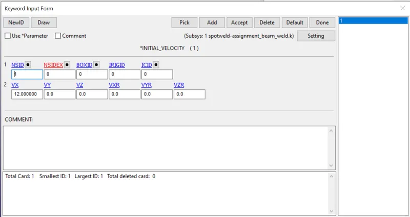
- Initial Velocity of 12 is given to all shell elements in the direction of rigid wall
Case 2: Solid Hexa element as Spot Weld
Create Solid Hexa spot welds
- In this case, instead of beam elements, solid Hexa elements are modeled
- The Hexa elements are created using the element creation option under the Eletool tab
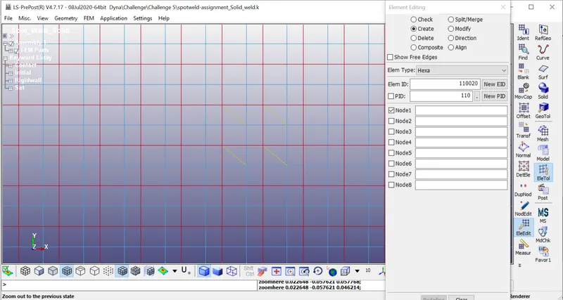
- Once the Hexa elements are created successfully, it is necessary to make changes in the Material card and Section card
- The same material can be assigned to solid elements
- Then, delete the section card which is created for beam elements and replace it with Solid elements with ELFORM 1
- Delete the contact TIED_SHELL_EDGE_TO_SURFACE and replace it with CONTACT_SPOTWELD
- The remaining is same as the Case 1
Results:
Case 1: Beam elements
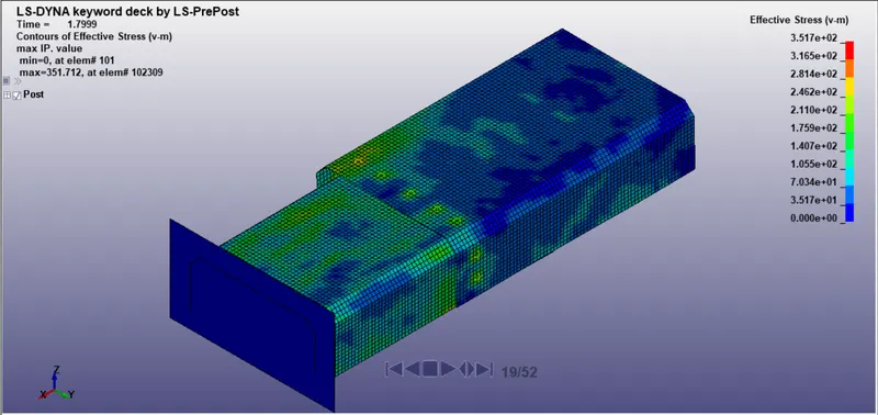
Case 2:
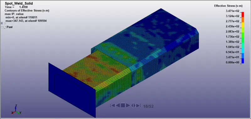
Axial and Shear Forces
Case 1:
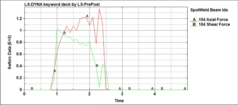
From the above observation, it can be stated that in case 1, shear forces rise at 0.8 ms, and after impact at 2.5 ms beam elements failed, it stablize. The maximum shear force is 103 MPa and axial force is 128 MPa
Case 2:
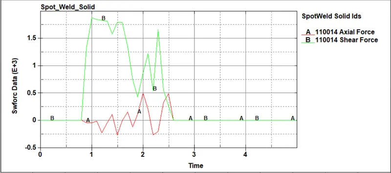
From the above observation, it can be stated that in case 2, a sudden rise in shear force occurs after impact and stabilize after the Spot weld failure. The maximum shear force is 153 MPa but axial force drops till -25 MPa
Acceleration Plot
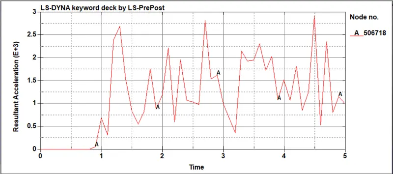
Case1: Highest acceleration can be seen near the 2.5ms with aplitude of 2.8E3
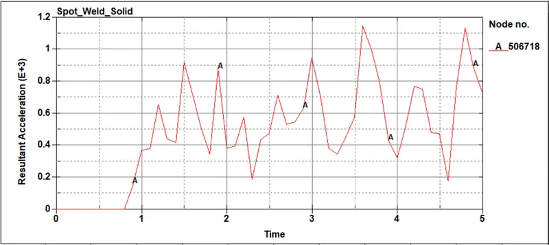
Case 2: Highest amplitude can be seen at 3.5ms with amplitude 1.1E3
Energy:
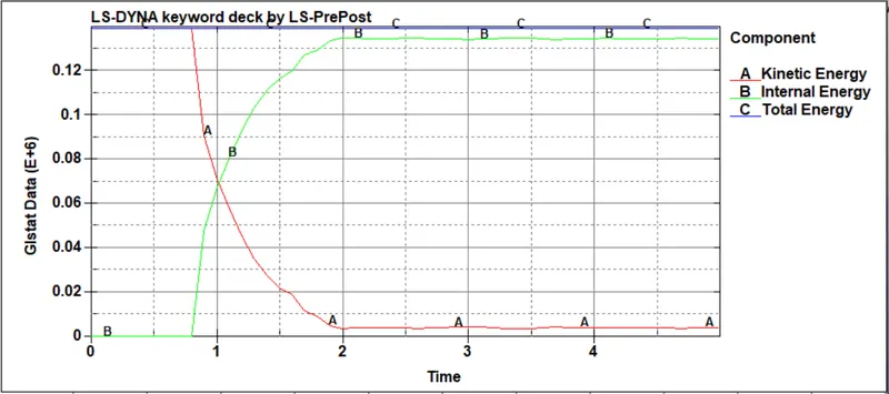
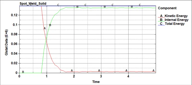
In both cases, kinetic energy decreases after impact and it gets absorbed by parts which in turn increases the internal energy. But total energy remains constant throughout the simulation.
Conclusion:
- All the objectives fulfilled, spot welds are modeled using 2D element(Beam) as well as Hexa solid element
- From the above results, we can say that solid welds are stiffer than beam weld