Week - 4 - Crash Box Simulation
Aim: To simulate a crash test simulation of crash box impacting Rigid wall in Ls Dyna
Objectives:
- To create a Rigid wall in LS Dyna
- Apply initial velocity of 50 Kmph to the crash box
- Compare the simulation results of the crash box having thickness 1.2mm and 1.5mm
- Plot the cross-sectional force generated in the middle of the crash box
Procedure:
The unit system followed is gm-mm-ms
Rigid Wall:
- Rigid walls are surfaces or volumes that are frequently used to represent stiffer structures that can be either stationary or in motion
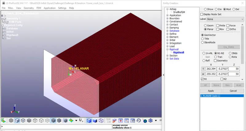
- A stationary planer wall is created in front of the crash box using create entity feature, Rigid wall>create>planer>Geo vector>N1-N2
- Rigid wall in translated to by distance in front of the crash box using tran feature
Initial Velocity:
- Before creating the initial velocity, Node-set ID for the entire shell element is created
- Create entity>Set_node> create new NODE_SET by selecting all element of crash box
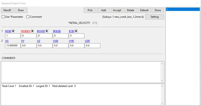
- Velocity is given in INITIAL_VELOCITY card ( 50 Kmph = 13.90 mm/ms)
Section:
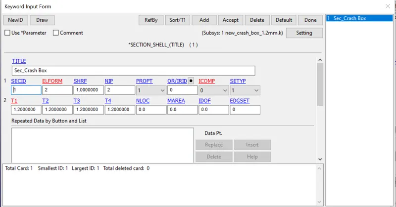
- The crash box is a shell element, which is selected through Select SECTION>SHELL>Section ID and Title
- Choose element formulation value in ELFORM as 2(Belytschko-Tsay type elements)
- Shell thickness is mentioned, for iteration1 as 1.2 mm and for iteration2 as 1.5mm
Material:
- For the crash box, non-linear steel material needs to be assigned.
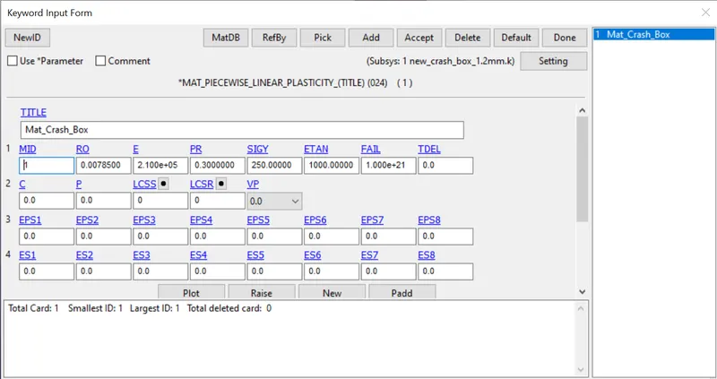
- Select MAT> 024_PIECEWISE_LINEAR_PLASTICITY material card is selected
- The value of density, Young's modulus, Poisson's ratio, Yield stress, and tangent modulus is entered using gm-mm-ms unit system
Hourglass:
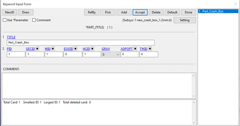
- Hourglass is defined using HGID. This keyword is used to reduce or control hourglass energy during the simulation
Part:
- All characteristics were assigned to the PART keyword
Contact:
In rigid wall construction, a Rigid wall is considered as Master and other elements are considered as Slave by default.
Control:
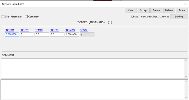
Define the termination time of the simulation which is necessary to run the simulation. the termination time of 5ms is used.
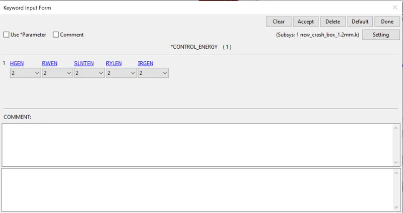
Control Energy: Now define the CONTROL_ENERGY card for energy dissipation
History node:
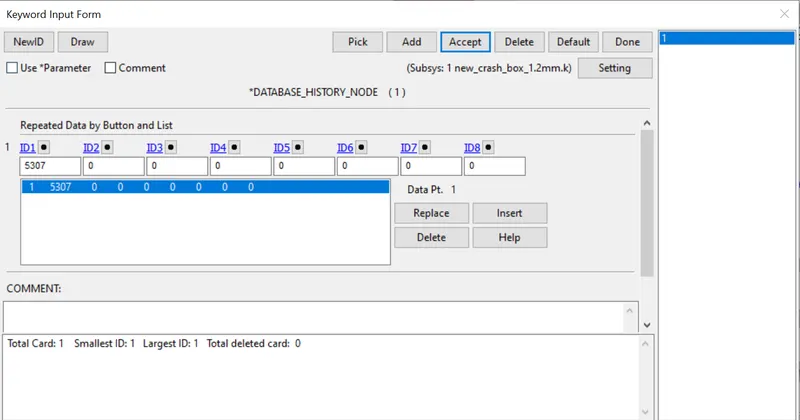
History node can be used to the acceleration at the node during simulation
Database:
The requested output is D3PLOT, history node and ASCII option are
ELOUT, MATSUM, GLSTAT, SLEOUT, NODOUT, SECFORC
Results
- Iteration1 = 1.2mm
A von misses, X-stress , X-stress simulation
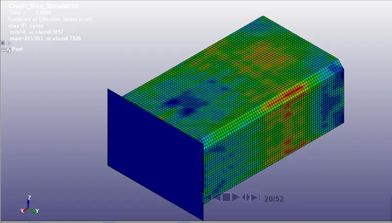
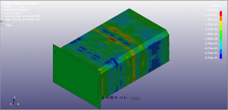
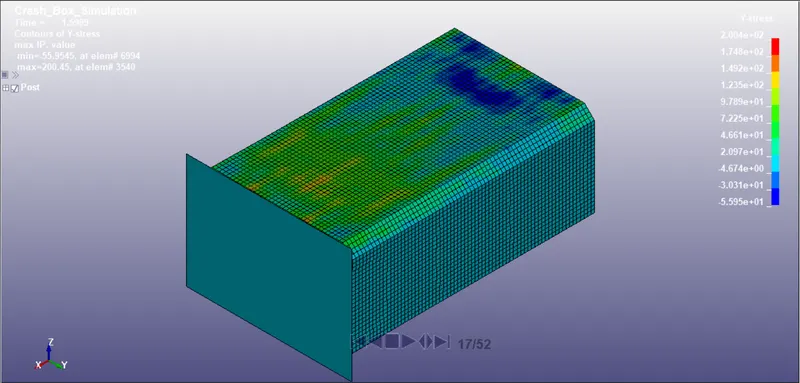
From the simulation, it can be concluded that the stresses are developed throughout the crash box. After impact, initially, the maximum stress occurs near the rigid wall and then gets transferred to the whole shell element. The stress distribution is uneven throughout the crash box due to vibration
- The maximum stress induced were 283 MPa
- The maximum stress in the X direction is 111 MPa
- The maximum stress in the Y direction is 200 MPa
Energy:
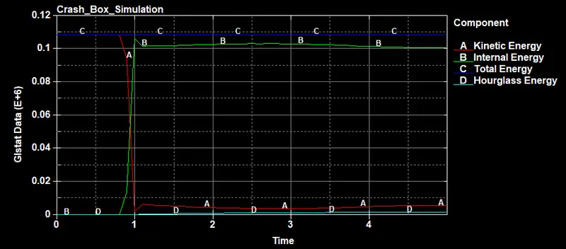
- From the graph, we can say that high kinetic energy before the impact is due to high velocity. Later, after impact kinetic energy gets absorbed by a rigid wall and it decreases.
- Total KE is converted into IE and due to negligible hourglass produced stable total energy can be seen
Acceleration:
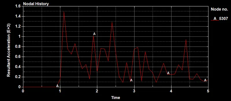
The maximum value of acceleration at Node ID 5307 can be seen at 1.2ms
- Iteration2 = 1.5mm
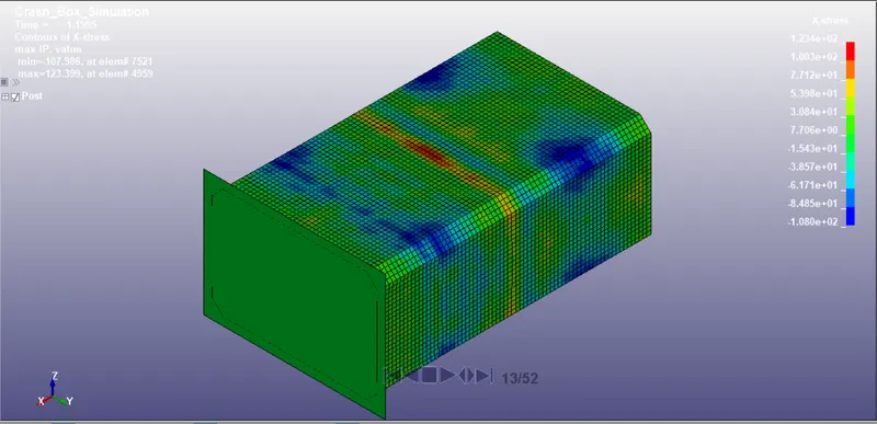
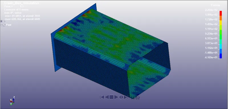
A von misses, X-stress , X-stress simulation
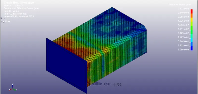
From the simulation, it can be concluded that the stresses are developed throughout the crash box. After impact, initially, the maximum stress occurs near the rigid wall and then gets transferred to the whole shell element. The stress distribution is uneven throughout the crash box due to vibration
- The maximum stress induced was 282 MPa, which is close to 1.2mm thickness shell
- The maximum stress in the X direction is 123 MPa which is more than iteration1
- The maximum stress in the Y direction is 226 MPa which is more than iteration1
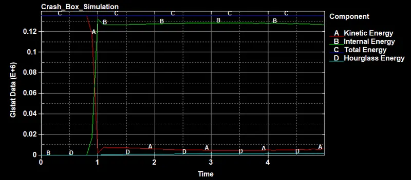
Energy:
- From the graph, we can say that high kinetic energy before the impact is due to high velocity. Later, after impact kinetic energy gets absorbed by a rigid wall and it decreases.
- Total KE is converted into IE and due to negligible hourglass produced stable total energy can be seen
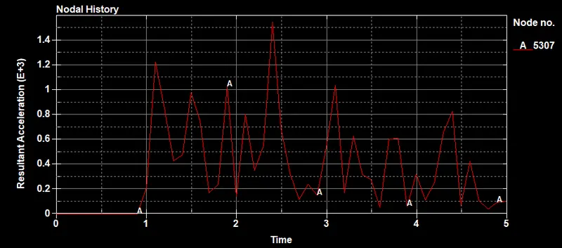
Acceleration:
The maximum value of acceleration at Node ID 5307 can be seen at 2.4 ms
Conclusion:
Crash box simulation is done successfully with 1.2mm and 1.5mm thickness respectively. All objectives are fulfilled and results are analzed