Week - 5 - Modelling Spotwelds
Aim:
To model the spotwelds for the given assembly of parts using beam and solid elements and the respective results are to be compared.
PROCEDURE:
Import the .K File into LS-PREPOST:
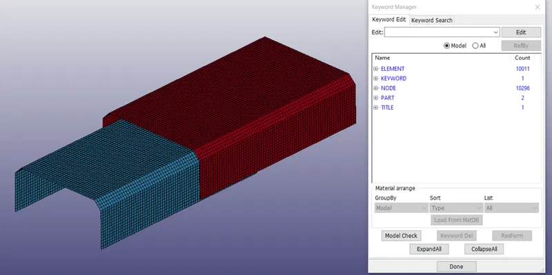
We can see only the parts are defined in the keyword manager.
Steps to follow:
1. Create a material card
2. Create the Section card
3. Assign the material and section to the parts
4. Create the beam elements / Create the solid elements
5. Create the rigid wall
6. Create the velocity card
7. Create the control card
8. Create the contact card
9. Create the sectional force card
10. Request for the Database cards
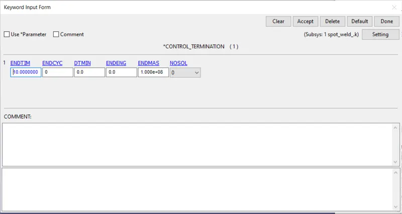
11. Create the Control Termination card
Step 1: Create a material card
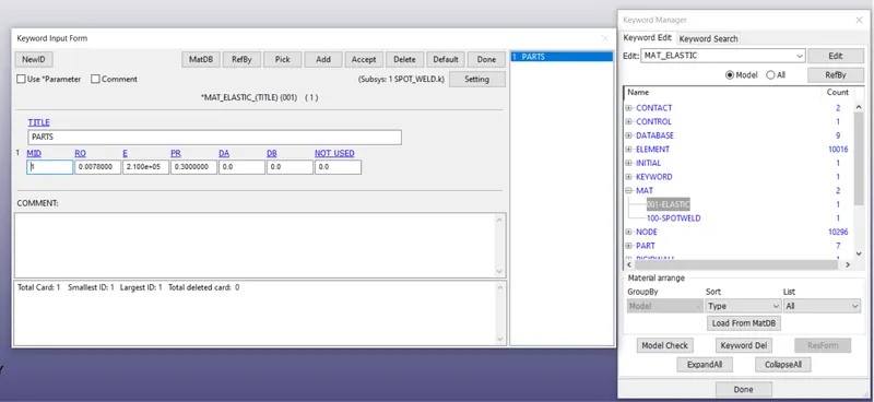
The material card used is *MAT_ELASTIC_PART.
We have to create the material for the parts given. Steel is considered in this case
Density = 0.0078 gm/mm^3
Youngs modulus = 210000 MPA
Poissons ratio = 0.3
Maximum stress = 350 MPA
STEP 2: Create the Section card
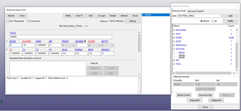
A Section card is defined for every part to provide the element formulation
ELFORM = 16 is used. (Fully integrated shell element)
The thickness = 1.5 mm is provided
Step 3: Assign the material and section to the parts
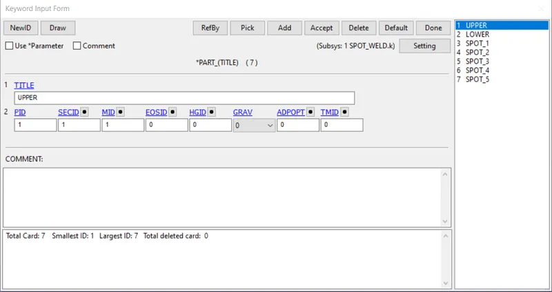
We have to assign the sections and materials created to the respective parts as shown below.
Step 4:
Creating beam elements:
Go to Element Tools >>> Element editing >>> Create >>> Elem Type: Beam >>> Select the nodes >>> Done
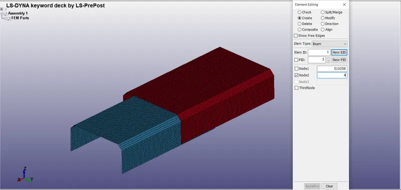
The created beam elements are shown below:
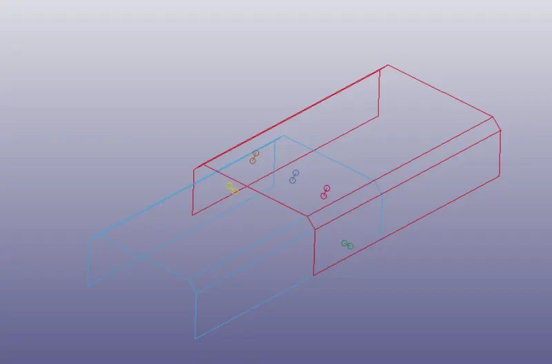
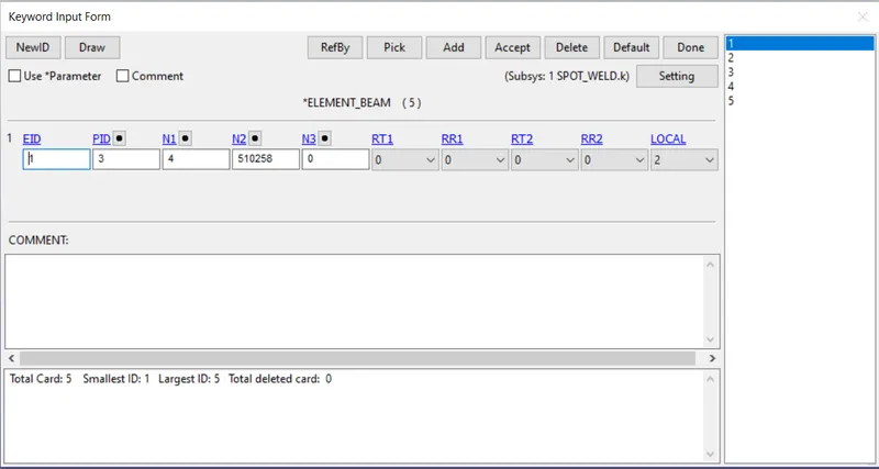
Creating Solid elements:
Go to Element Tools >>> Element editing >>> Create >>> Elem Type: Hexa >>> Select the nodes >>> Done
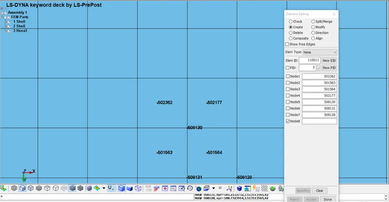
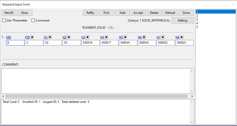
The created solid elements are shown below:
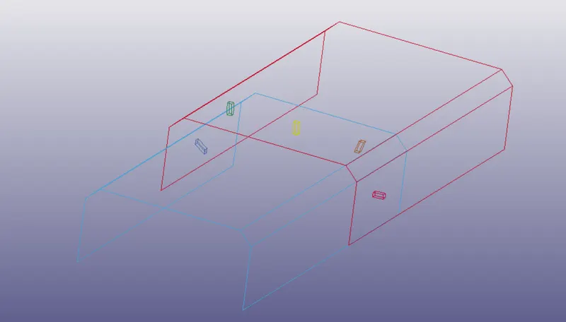
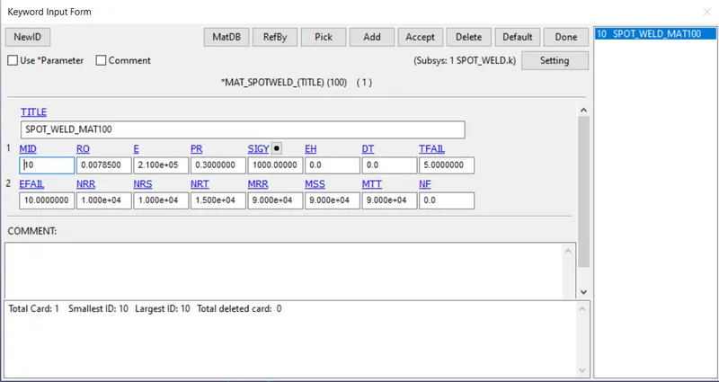
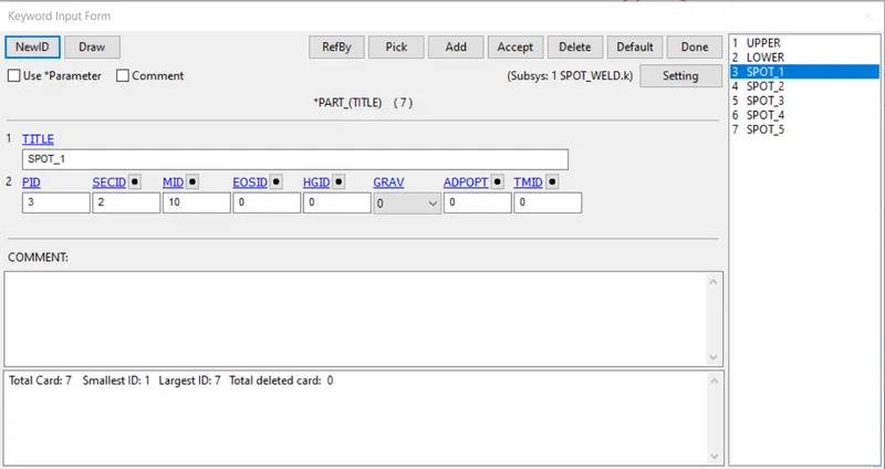
Material has to be created for the weld elements:
Mat_Spotweld_MAT100 is used for the beam elements.
The Steel properties are provided.
TFAIL is assigned as 5 ms, It is representing that the beam elements should fail at 5 ms i.e., halfway of the simulation.
The section is created using ELFORM = 9, i.e., Spot weld beam.
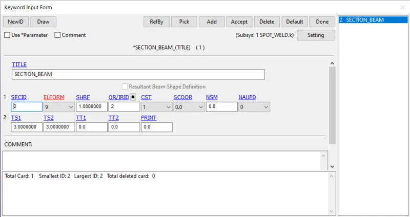
We have to assign the sections and materials created to the respective parts as shown below.
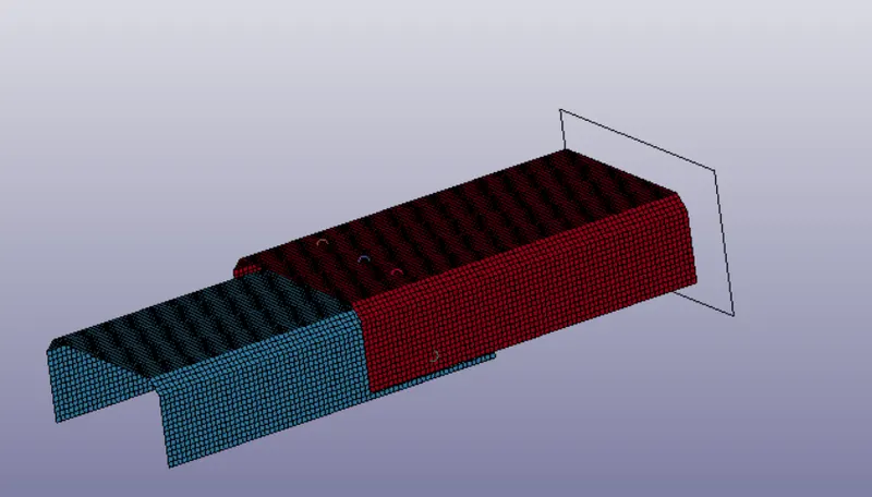
Step 5: Create the rigid wall
Go to create entity >>> Rigidwall >>> Create >>> Planar >>> By nodes >>> translate global and provide some gap.
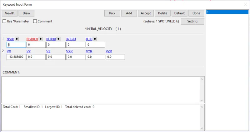
Step 6: Create the velocity card
Go to keyword manager >>> All >>> Initial >>> Velocity
Create the node set for the whole crash box and assign it as NSID.
Provide the velocity for the assembly towards the rigid wall
V = -13.888 mm/ms
Step 7: Create the control card
Control energy card:
To consider the Hourglass energy, Sliding energy, Rigid wall energy, we have to activate the respectives in the Control_Energy card.
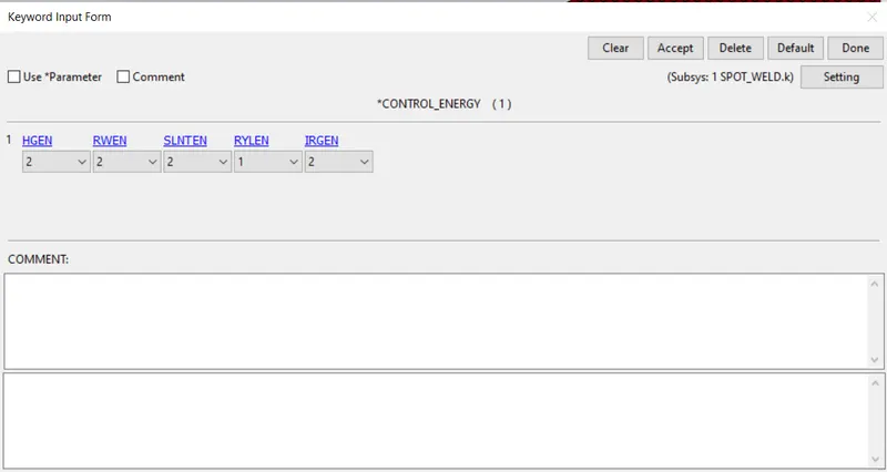
HGEN: Hourglass energy is computed and included in the energy balance.
RWEN: Rigid wall energy dissipation is computed and included in the energy balance.
SLNTEN: Sliding interface energy is computed and included in the energy balance.
Step 8: Create the contact card
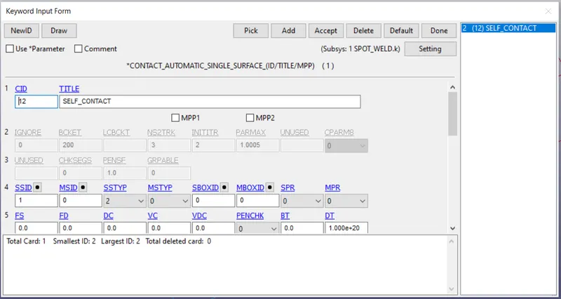
Automatic_single_surface is used to define the self contact.
It takes reactions and energy into consideration that are due to self contact.
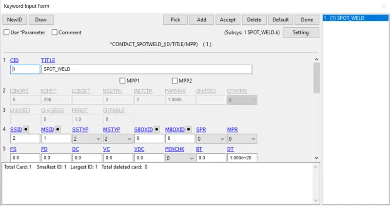
*Contact_Spotweld card is used to define the contact between the beam/Solid elements and the parts
Select the weld segments or parts as slave and The parts as the master.
Step 9 : Create the sectional force card
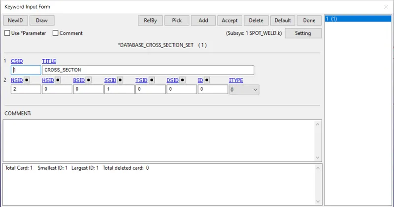
Create the node-set and Shell element set at the middle of the crash box.
Enable the Database_Sectional forces and assign the NSID and SSID to the card.
Step 10: Request for the Database cards
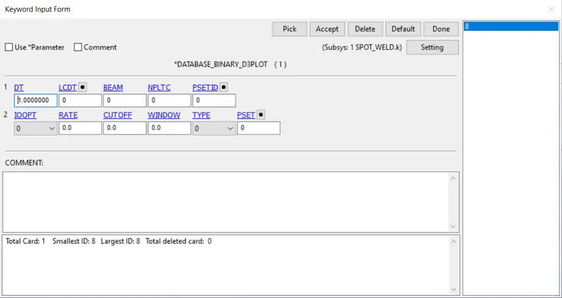
Request for D3PLOT:
DT = 0.1 :Time interval at which the animation files should be printed.
Step 11: Create the Control Termination card
Control_Termination card is to be provided to specify how much time this simulation has to run.
Results:
SOLID ELEMENTS:
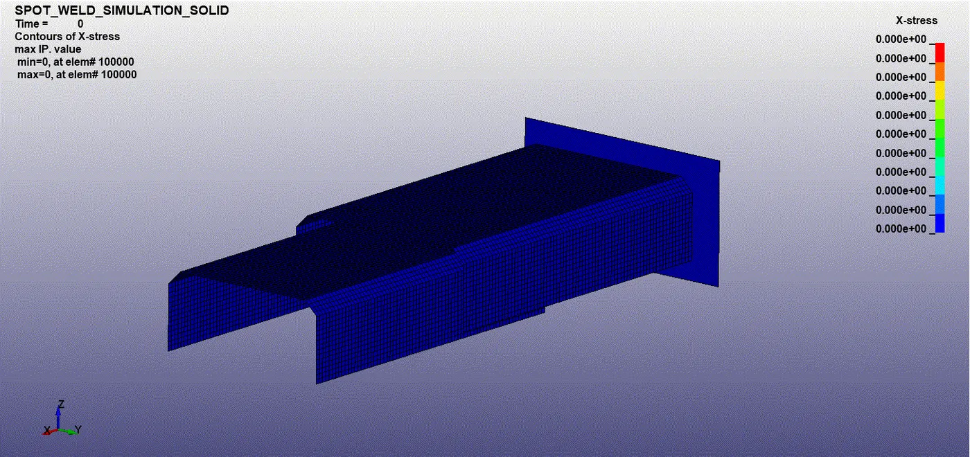
The maximum X- Stress is seen at node ID 102511: 1703 Mpa.
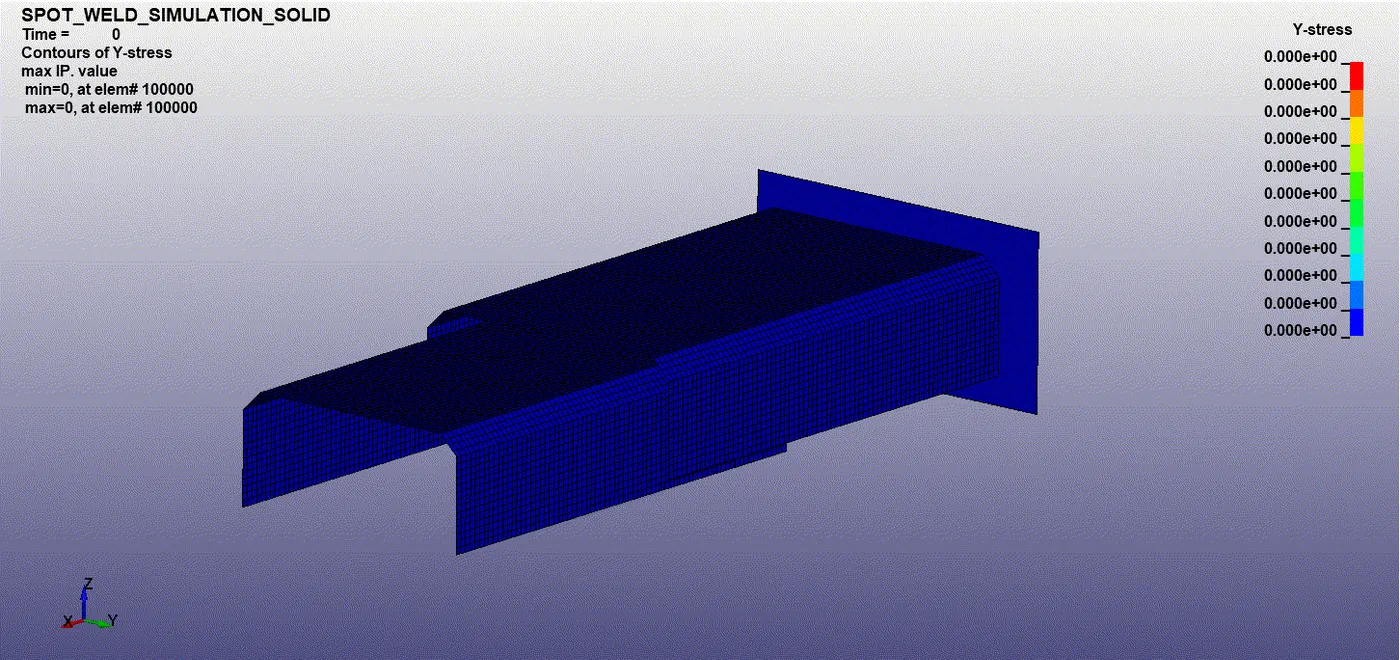
The maximum Y- Stress is seen at node ID 108184: 909 Mpa.
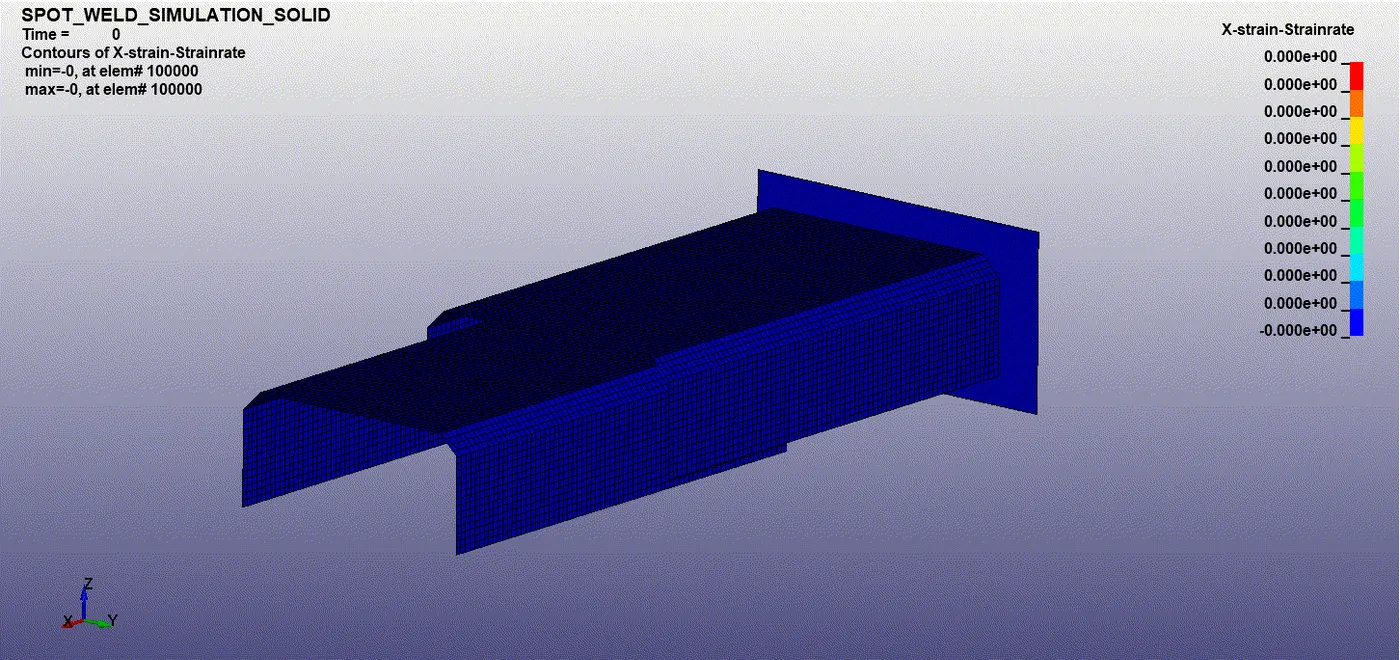
The maximum X-Strain is at node ID 103764: 0.5019
The maximum Y-Strain is at node ID 102075: 0.3839
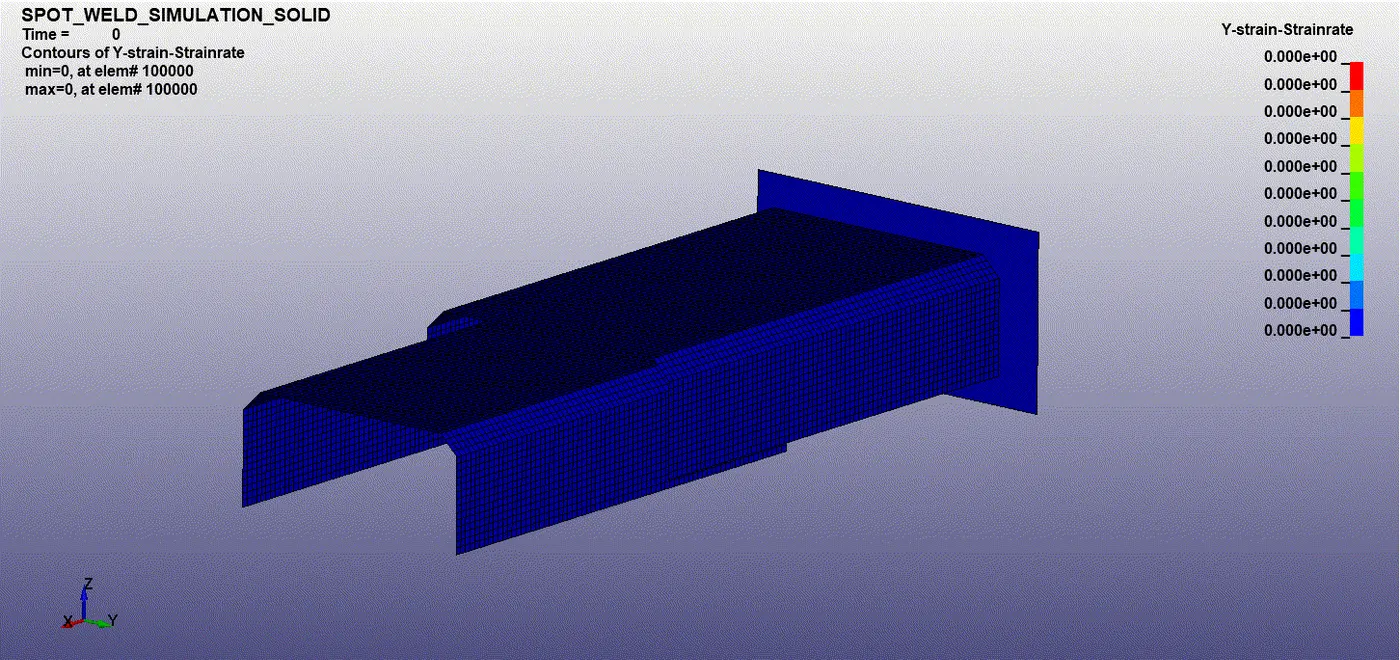
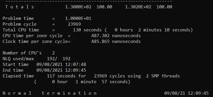
The Normal termination is shown as there are no errors and the simulation is executed well.
The total time taken for the simulation = 130 seconds.
Plotting:
We plot the energies, Sectional forces, Nodal acceleration using post-processing
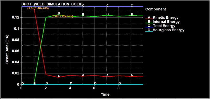
Global data is plotted as shown below, which consists of internal energy, kinetic energy, hourglass energy, total energy.
We can see as soon as impact happens the kinetic energy due to the initial velocity gets decreasing there by increasing the internal energy.
The hourglass energy is zero because of the recommended properties like full integration.
The total energy is constant through out, because of decreasing kinetic energy and increasing internal energy.
Crashbox 1.2mm:
Maximum Internal energy = 1.2 E+5 kJ
Maximum Kinetic energy = 1.40 E+5 KJ
Maximum Total energy = 1.40 E+5 KJ
Maximum Hourglass energy = 0.000 KJ
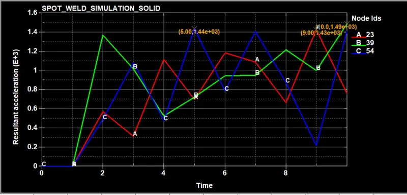
The resultant accelaration at the node id's on the part is shown below
The Resultant force at the cross section i.e., created is plotted
The maximum resultant force is at 6th second = 2.96 e+03 KN
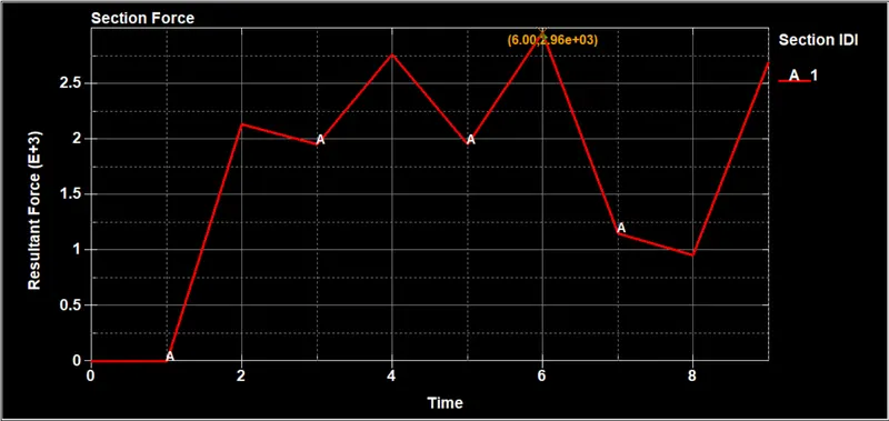
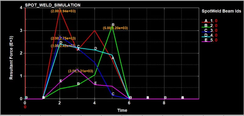
We can see the resultant force acting upon the weld joints, and the force is zero from the 6th second as we wish the fail to happen at that point.
Beam elements:
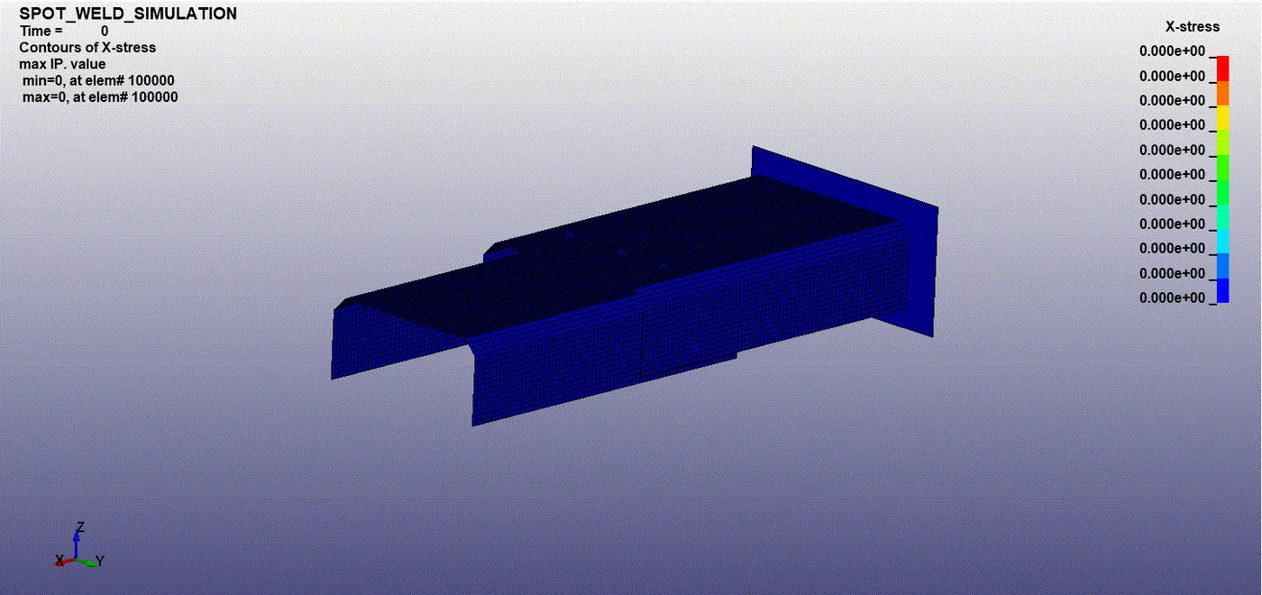
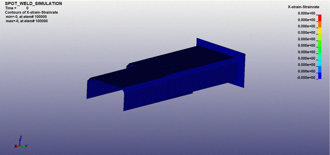
The maximum X- Stress is seen at node ID 104304 is 1.487e+03 MPA
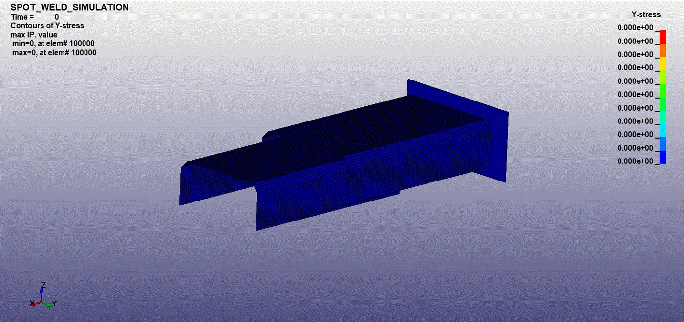
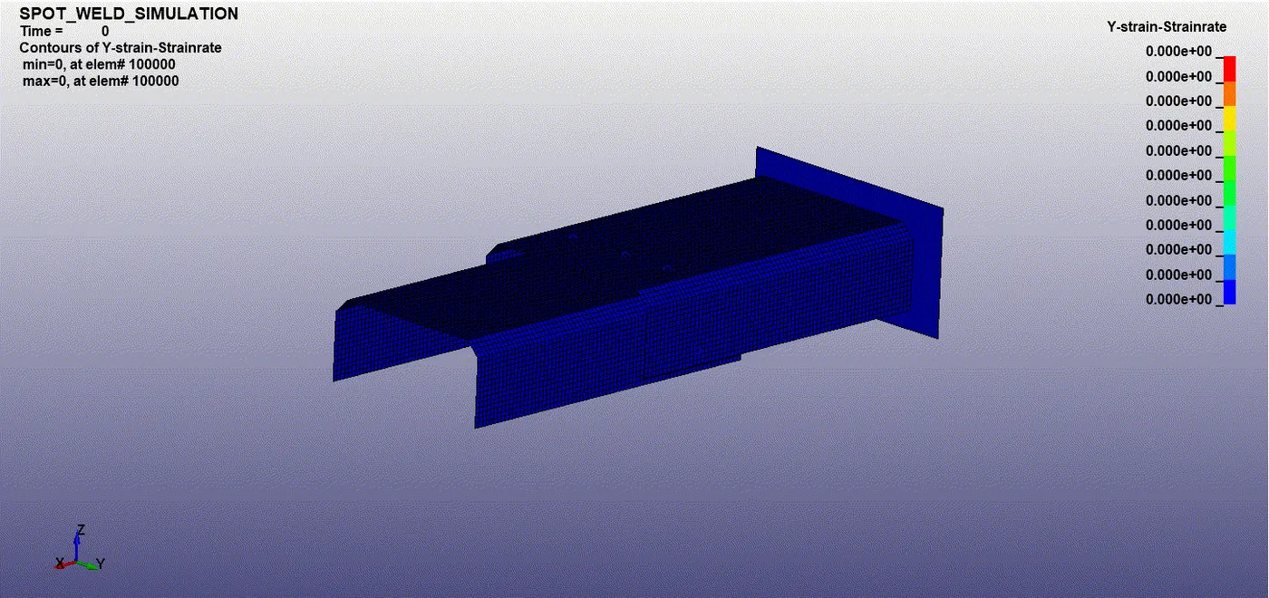
The maximum Y- Stress is seen at node ID 102357 is 1.215 e+03 MPA
The maximum X- Strain is seen at node ID 102883: 1.257
The maximum Y- Strain is seen at node ID 103790: 0.6927
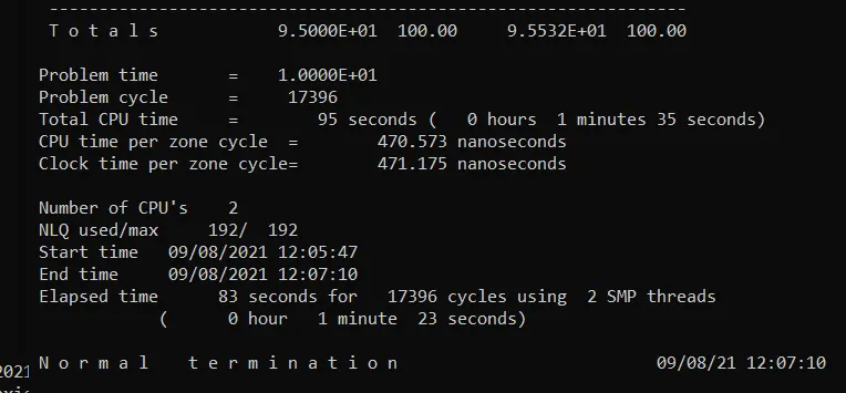
The Normal termination is shown as there are no errors and the simulation is executed well.
The total time taken for the simulation = 95 seconds.
PLOTTING:
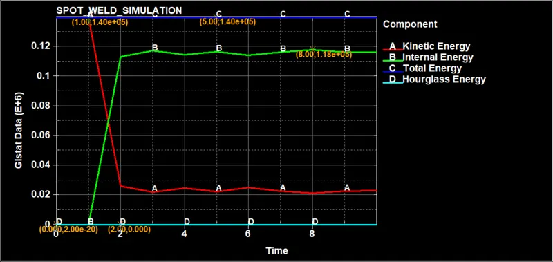
Global data is plotted as shown below, which consists of internal energy, kinetic energy, hourglass energy, total energy.
We can see as soon as impact happens the kinetic energy due to the initial velocity gets decreasing there by increasing the internal energy.
The hourglass energy is zero because of the recommended properties like full integration.
The total energy is constant through out, because of decreasing kinetic energy and increasing internal energy.
Crashbox 1.2mm:
Maximum Internal energy = 1.2 E+5 kJ
Maximum Kinetic energy = 1.40 E+5 KJ
Maximum Total energy = 1.40 E+5 KJ
Maximum Hourglass energy = 0.000 KJ
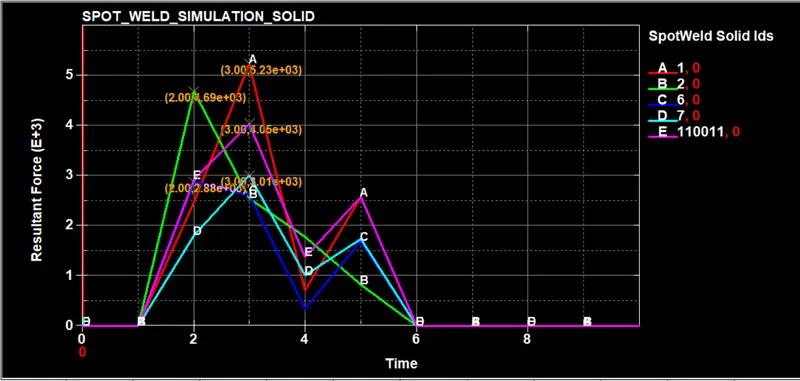
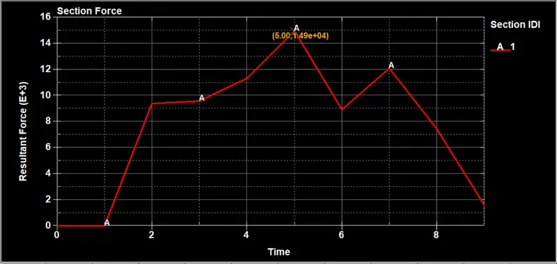
The Resultant force at the cross section i.e., created is plotted
The maximum resultant force is at 5th second = 1.49 e+04 KN
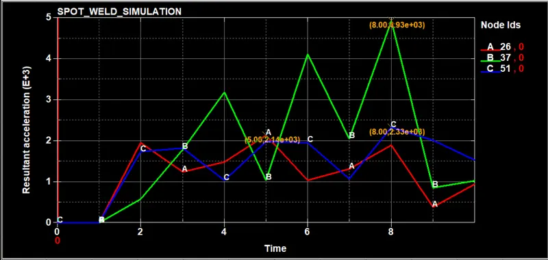
The resultant accelaration at the node id's on the part is shown below
We can see the resultant force acting upon the weld joints, and the force is zero from the 6th second as we wish the fail to happen at that point.
Comparison:
| Maximum | Beam element | Solid element |
| X-stress | 1487 MPa | 1703 MPa |
| Y-stress | 1215 MPa | 909 MPa |
| X-strain | 1.257 | 0.5019 |
| Y-strain | 0.6927 | 0.3839 |
| Energy | Beam element | Solid element |
| Kinetic Energy | 1.4 E+05 KJ | 1.4 E+05 KJ |
| Internal Energy | 1.2 E+05 KJ | 1.26 E+05 KJ |
| Total Energy | 1.4 E+05 KJ | 1.4 E+05 KJ |
| Hourglass Energy | 0.000 | 0.000 |
| Beam Element | Solid Element | |
| Resultant Force | 1.49 E+04 N | 2.96 E+03 N |
| Max. acceleration | 4930 mm/ms^2 | 1490 mm/ms^2 |
Conclusion:
We can observe that the weld elements fail at the TFAIL and the parts are getting into contact, thereby increasing the stress in the components.
We can see that the acceleration is not constant, at first acceleration decreases due to drop in velocity of the component and then goes up and doen as shown in the figure.
The top plate bounces back due to impact where as lower part continues to go in the direction of weld joints.
TFAIL is used to study the damage that occurs due to the failure of weld joints that are connecting the parts. Generally the failure criteria is drawn from the experimental results.
The Sectional forces are obtained , which helps in understanding how much force is transfered through the particular part and how forces are distributed in the big assembly.
The nodal data is also obtained to check how energies are generated.
From the spot weld forces, we can see how forces are generated in the beam and solid weld elements over the timeduring the impact.