Week 5 Challenge : Surface wrap on Automotive Assembly
LINK:- https://drive.google.com/drive/u/1/folders/1Vzq8UtV-f5NlJQXkezKC_Llfbcu9HDPR
Aim:-
This week for the given model we need to check the geomentry errors and delete the unwanted surface for a surface wrap.
Procedure:-
 =>
=>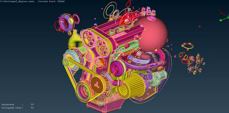
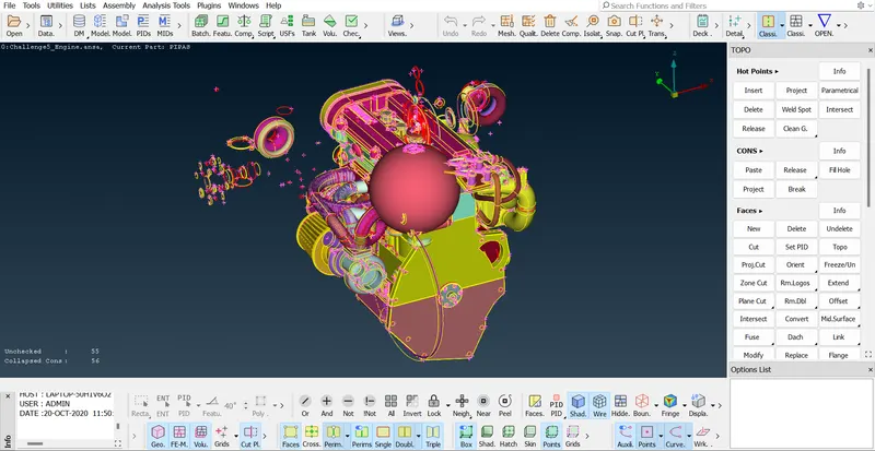
- In this challenge we will deal with surface warp. so, the surface warp is used for moving the components. form outside so, we will not be dealing with the surface which is presented as insider components of the particular.
 =>
=>
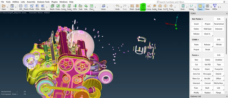
- So, our task is to remove all the unnecessary surfaces from the outside and to patch the surface very fully. so, that we should not have any holes or any dent in our particular model.
- the surface warp is used to analyze or to study the outside flow and simulation or analysis.
- Our analysis is don't require any internal component. which is required only on outer side components or surfaces for that kind of study we can use this particular surface warp option.
- So, the surface warp is used by tapping a component and then matching that particular warp accordingly by giving suitable quality criteria.
- Similarly not only this one component and also we will going to deal with two more components. that is the engine transmission and gearbox. so, in total, we have three components. so, we will try to do topo clean up for all three separately and then we will do surface warp industrially.
- After we do surface warp individually we will try to merge all three components and then will make an assembly.
 =>
=> =>
=>
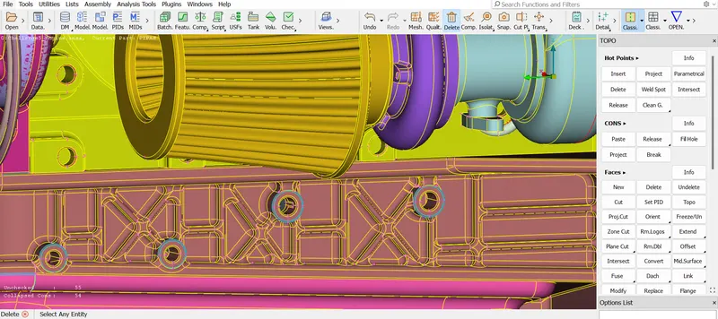
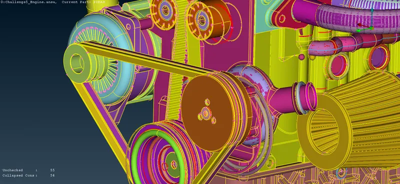
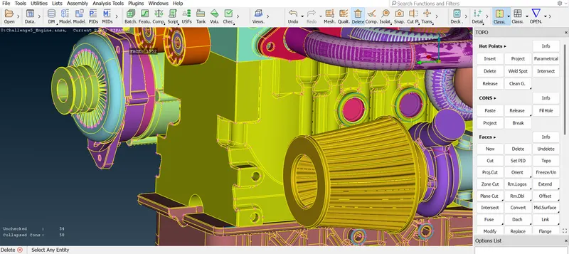
- So, before doing surface warp, we should clarify that no component or there is no unwanted surface present outside in our geomentry.
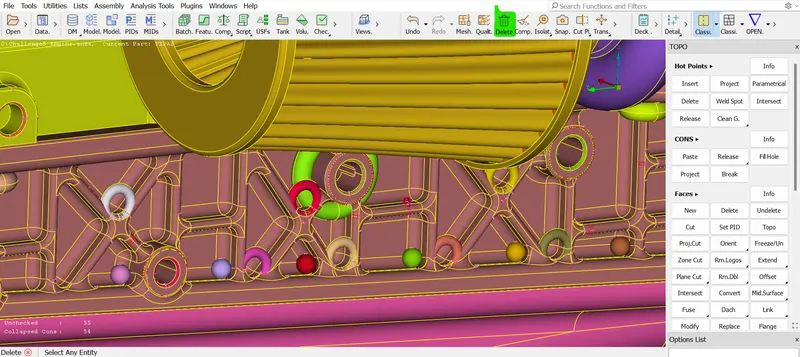
- So, to clear geomentry first of all we need to remove all these surfaces which are present in the outside areas of interest. so, drag select the unwanted surfaces first and then use the universal deleted option.
 =>
=> .
.
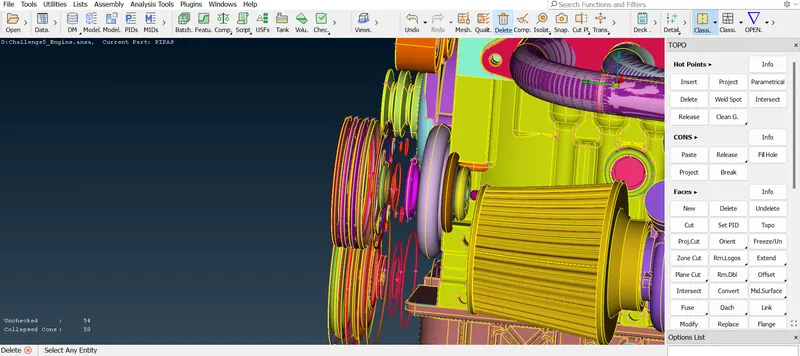
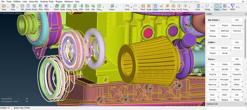
- To delete the surface you need to set the view so accordingly. so, that we can make the box selection and we can select only the surface which we don't want to have in our model. so, our view will play a major role.
- And also we can use the view option. once click the option we can see the model from a different angle view. so, that it is easy to delete the unwanted surface by checking those multiple views.
- Make sure before deleting the surface we should be confident that the surface is not required in a model. and we can also zoom in and zoom out by confirming whether the surface is required or not.
 =>
=>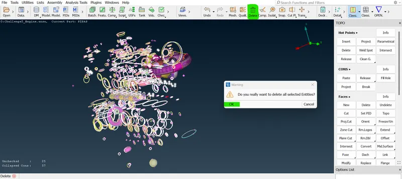
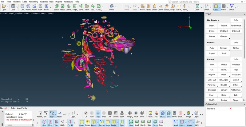
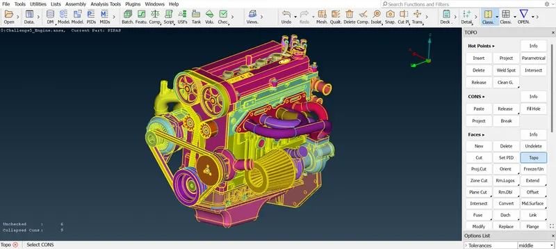
- Here on this surface there are a lot of rings presented that are not at all used because they are isolated and it does not touch any components. so, it has no significance in real life. so, we can delete that.
- There are many duplicated surfaces presented. so, the duplicated surfaces are removed and also the rings are needed to be deleted.
- So, many rings are presented outside so, we can delete those rings part by part. and once we got an idea to delete those rings then we can go for deleting by checking a geomentry.
- even we can try another method for deleting those rings. First hiding the required surface using PIDs. And then the rings are got isolated. so, it is easy to identify and delete those.
- Now, we will release the lack and we will click all options now you can see that the surface is much good the earlier rule this is how we can delete unwanted surfaces and duplicate surfaces individually.
 =>
=> =>
=>
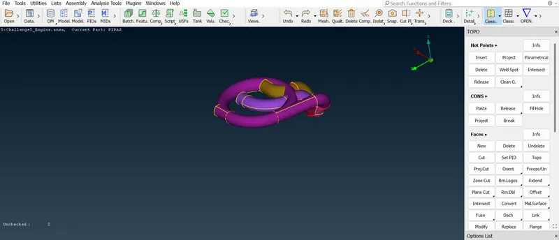
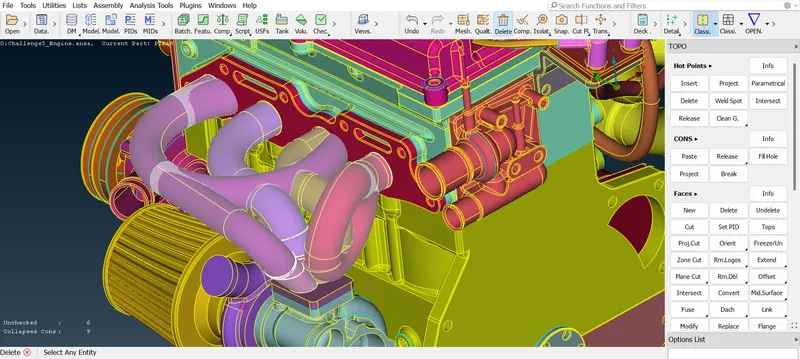
- In this exhaust tube side there are a few surfaces that are not in a continuous manner and which are not closed. so, we should delete those surfaces that are present.
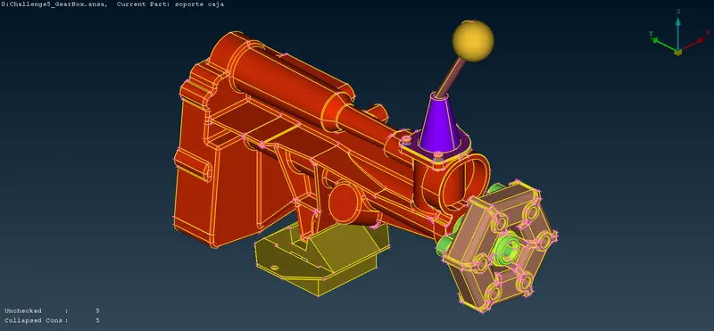
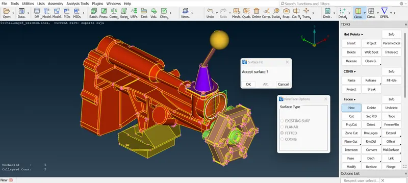
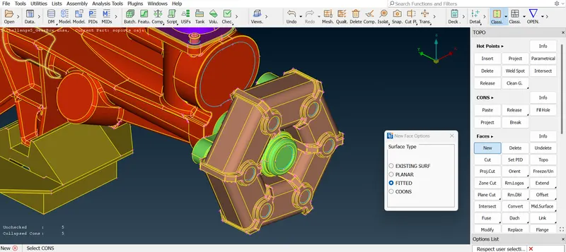
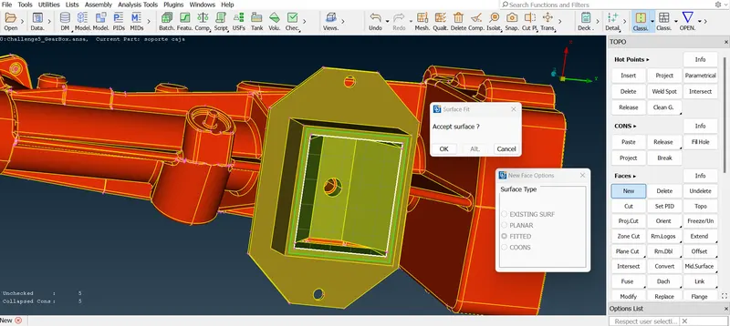
- Now we are having a gearbox model. so, we will work with this model. so, in this model first, we need to do some topo cleanup work. like we have to remove the overlapped surface and then some deleting and joining processes also we have to do.
- In this gearbox model we have deleted some overlap surfaces and if needed we can create the surface over there and also we need to create some surface if needed.
 =>
=>
 =>
=>
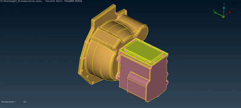
- Now, we are having another model which is nothing but transmission. In this middle, we need to delete the unwanted rings and some overlapped surfaces and also we needed to recreate some of the surfaces.
- In this model select PIDs mode and isolate the nut region alone. and you can see there are triple cons presented which is there are inside surfaces presented. so, we need to delete those surfaces. after that do topo and then the triple cons surface is gone.
- So, we have deleted all these surfaces or all these particular features which are not connected with our primary components. so, we can start with surface wrapping.
- Now we will going to merge all three components in this single GUI and after that, we will also going to do the surface wrap.
- So, before going to warp we will need to confirm that is there any unwanted surfaces are present. and make sure also close the hole present in those models.
=>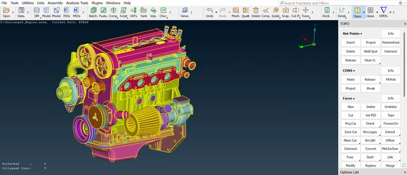
- Delete the entire pipe present in this backside surface of the model. so, those pipes are unnecessary surfaces for this wrapping process.
- After deleting the pipe surface there is a lot of ring feature and overlapped surface feature presented there.
=>
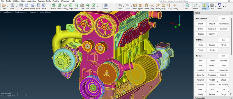
- And we need to remove the belt and the pully so, because these are very thin parts so, these thin parts are not captured properly in our surface wrap.
 =>
=>
=> .
.
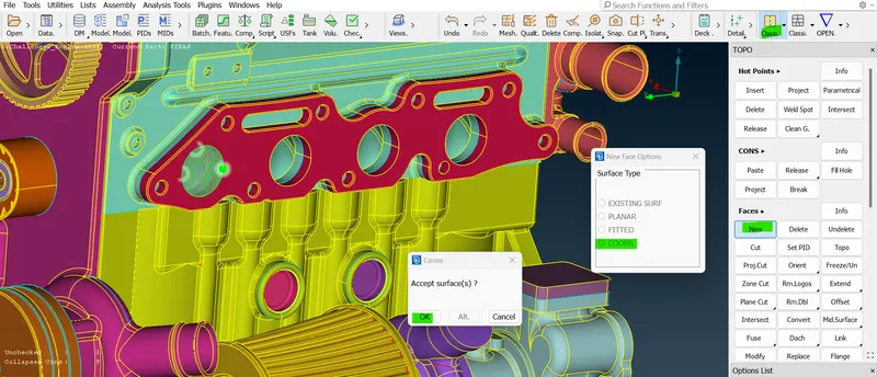
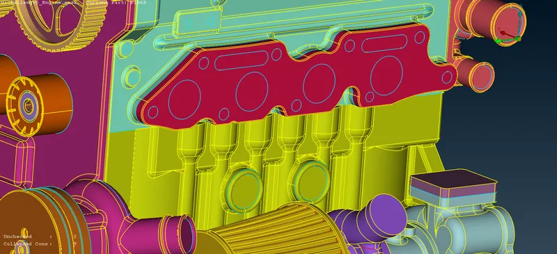
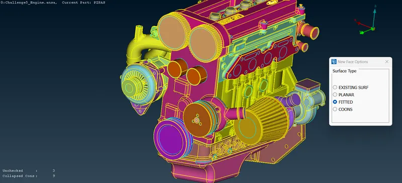
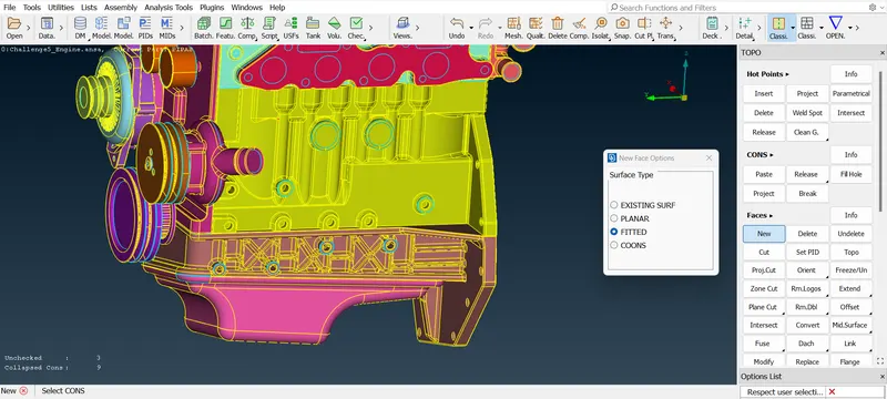
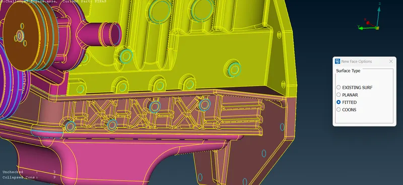
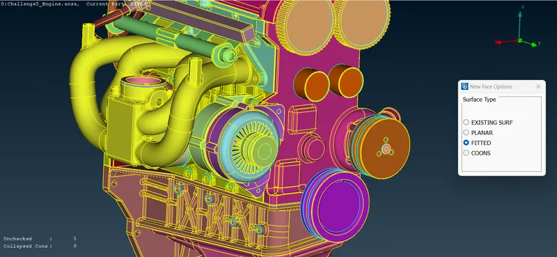
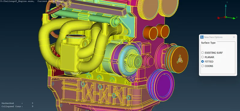
- And check the model entirely if there are any holes presented then consider patching the hole using a new surface before wrapping. so, then only our surface wrap will get as we expected manner.
 =>
=>
 =>
=>
=> .
.
- After completing patching the hole in the engine model and we can ensure that the hoke is patched then we can move the surface wrapping the model.
- The surface wrapping is used to analyze the outer flow or internal flow of the particular model. so, before doing surface wrap we will be ensuring that we have a closed volume.
- Now we can assemble our model in geometry we can directly do the surface wrap at one time and then we can have a common volume.
 =>
=>
 =>
=>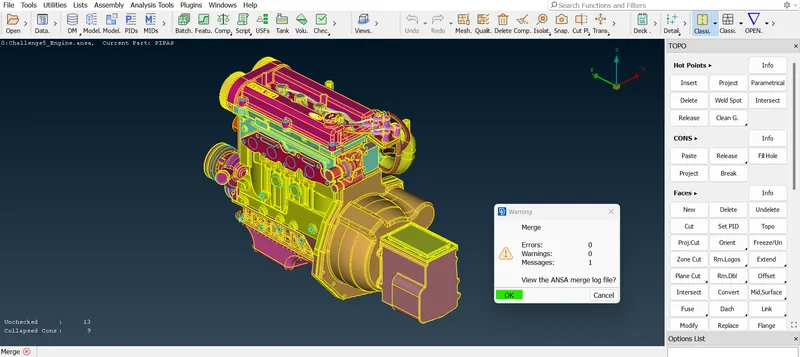
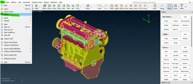
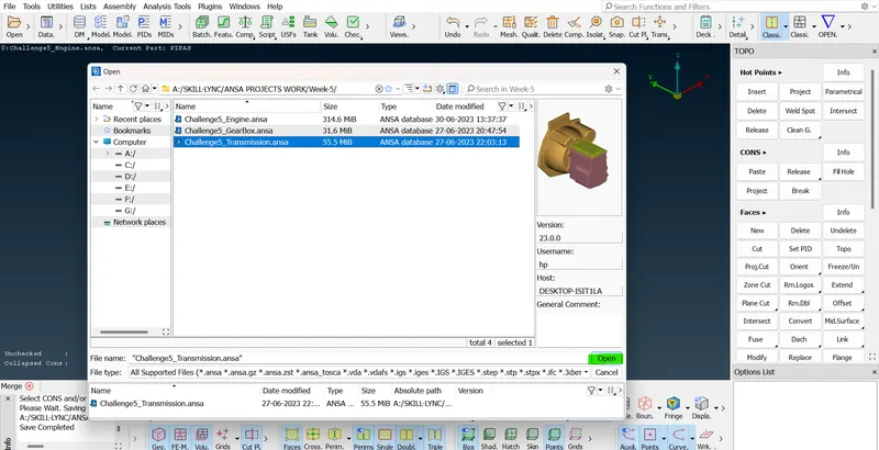
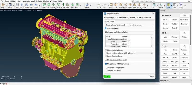
- Now we are going to merge the engine with another model. in this GUI only. so, Go to FIle--> click merge--> select the transmission model and click open--> now click OK in another popup box--> again click OK. Now the second model is merged with the current model.
- And repeat this merging process for the third component. after completing this process. we need to patch holes in these entirely three models. after patching the hole in this entire model and removing the unwanted ring or surface. now it is time for doing the surface wrapping of the model.
 =>
=>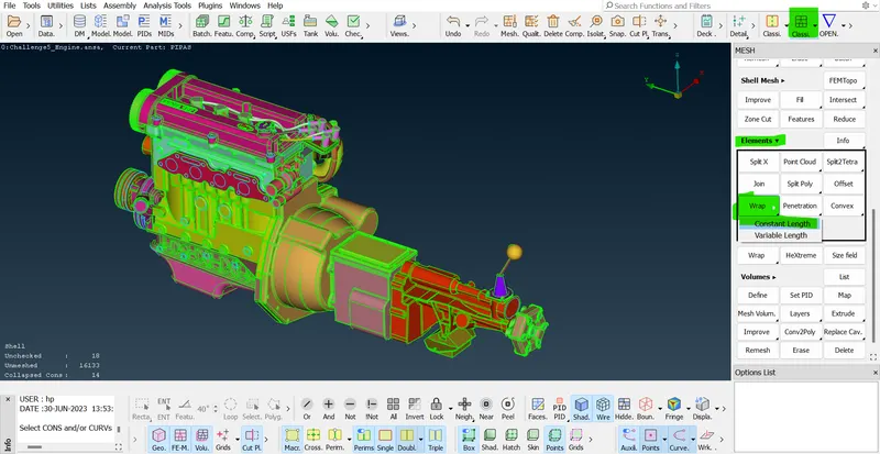
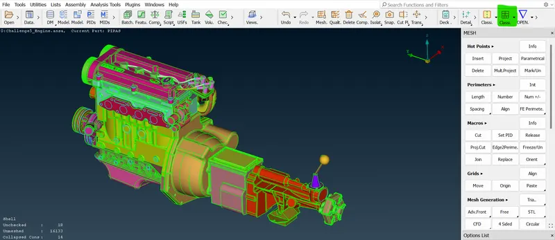
- Now click the mesh tag which means switch to mesh mode. and then go to element selection then click the wrap option in that. we need to select the constant length. The constant length is taking only one target length through the model.
- So, here we can create a waterTight surface mesh around an assembly that may have FEM or macros. watertight in the sense that will not have any gap over a surface which is nothing but a closed surface or volume. so, whatever is inside their particular regular warp will form a common volume instead of a different volume.
- If we are doing the outer side flow simulation you can also create an internal and then you can have a volume between your wind tunnel and this particular assembly wind tunnel and this particular assembly and then we can delete the volume inside this assembly and then we can also perform flow over a particular component simulation.
 =>
=>
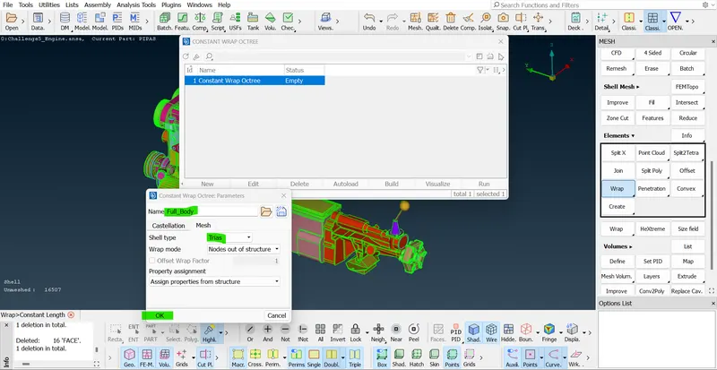
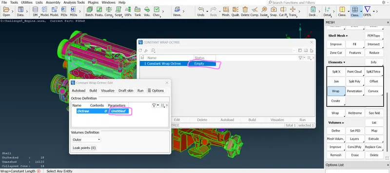
- After selecting the constant length now double click the status area now in the another tab. we need to enter the value in the parameter section and the contents section.
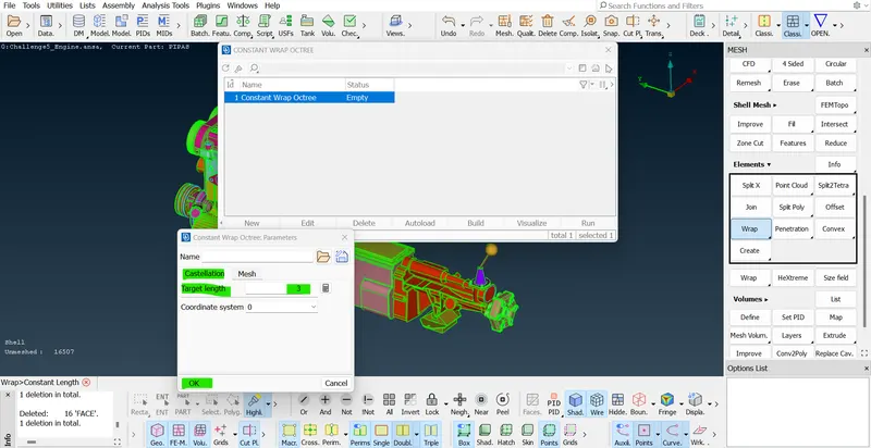
- Double click the parameter--> ENter the target length--> section mesh option in that tab select 0.5 in smooth target and click OK.
- If we give the target length is very smaller then the mesh will come very accurately. and also it will take some extra time if we give the target length a little bit higher than the smaller length then the mesh will be got it quickly at the same time the accuracy has not got that much.
 =>
=>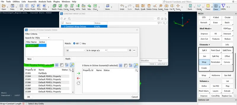
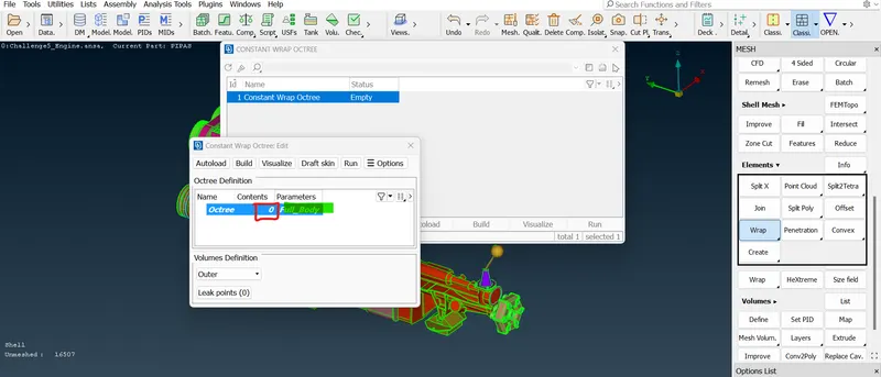
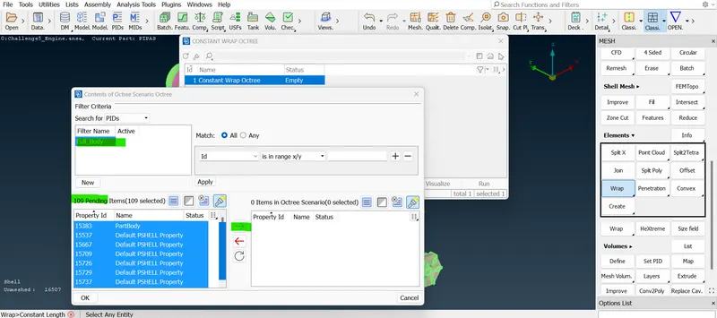
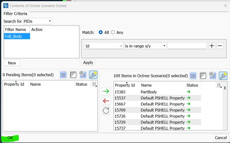
- In that tab the content is 0. so, double click that 0 and then give the content name and select the entire PIDs. and move that frame from left to right and click OK.
 =>
=>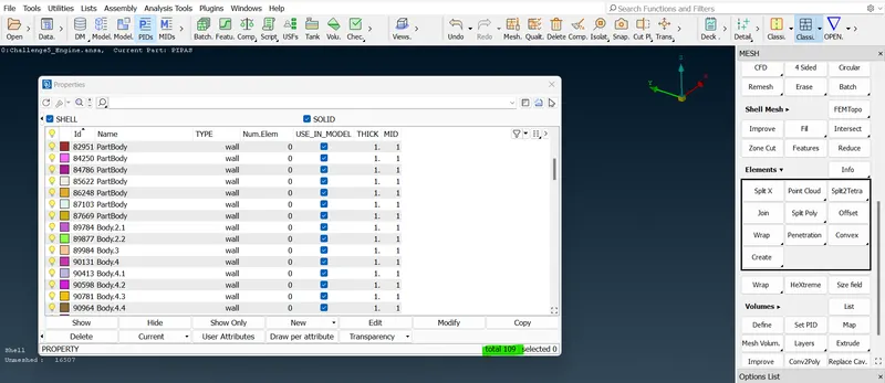
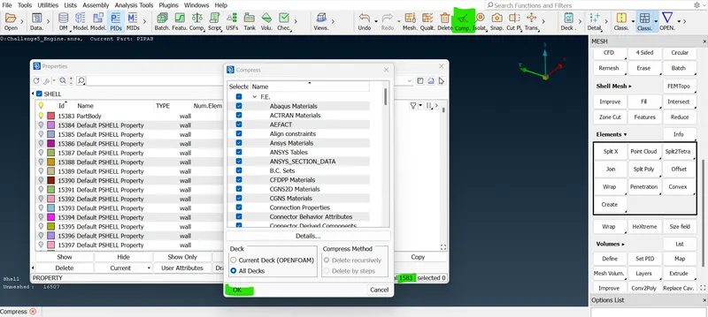
- So, before selecting the PIDs we need to delete the unwanted PIDs by using the compress option.
 =>
=>
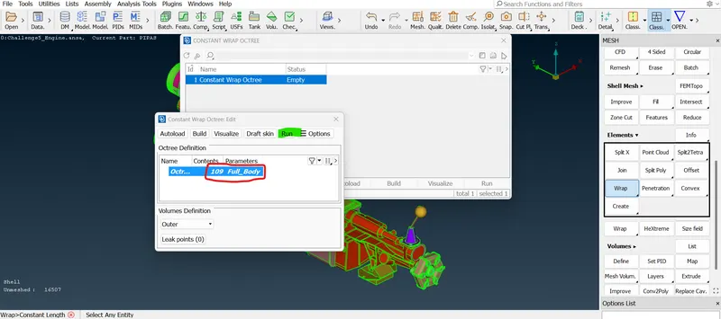
- Now the parameter is also given and the content is also given so, it is a good time to run the wrap. so, click the RUN button in that tab.
 =>
=>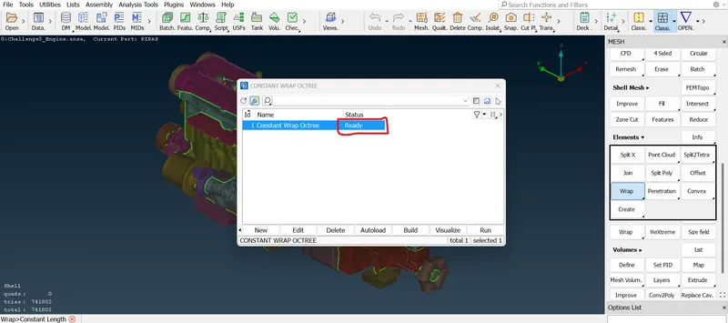
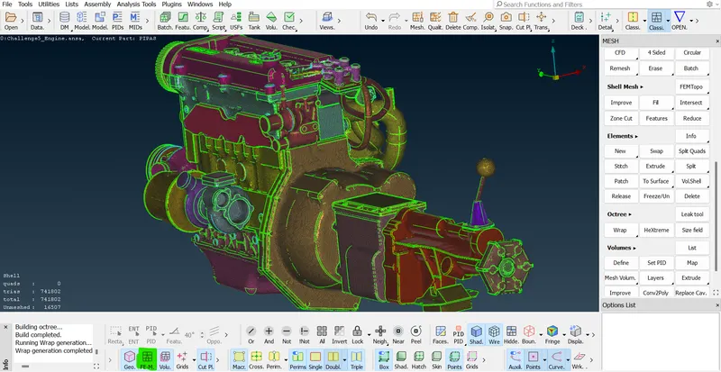
- After RUN we can see that the wrap has been coming in our entire model perfectly came in our entire model. and also we can turn on and off the FE mode and geomentry mode.
 =>
=>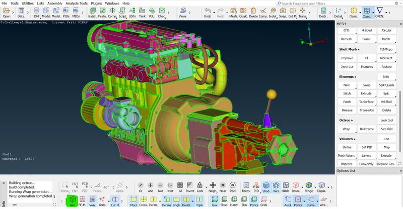
- Once turn off the FE mode by clicking that icon the wrap gets hidden. if we turn on that then the wrap will come back again we can also check the inside volume in that wrap.
 =>
=>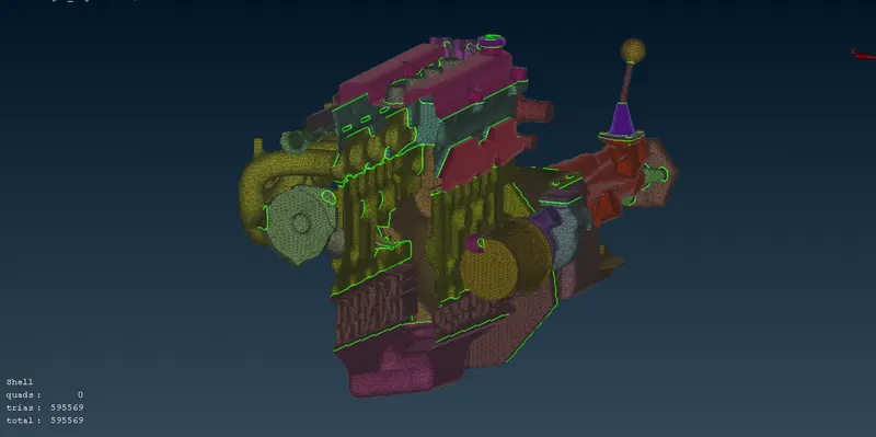
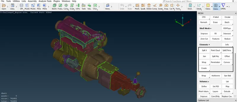
- The geomentry is our main model which is we can hide and unhide the modal. If hide our geomentry model then we can see our volume.
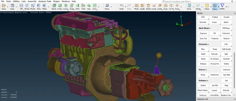
- so, Here our surface warp has been completed.
Learning Outcome:-
In this week I have learned how to surface wrap a component and how to merge multiple components with the current component. and as usual, we learned how to clean the topology and give a target length for the surface wrap.
Result:-
Hence, For the given model we have done checking the geomentry errors and deleted the unwanted surface for a surface wrap. And we have merged the component and wrapped the components successfully.
Conclusion:-
Finally, I have concluded here I've given surface wrap for the engine, gearbox, and transmission and merged them as they said in the question criteria.