Week 3 Challenge : CFD meshing on Turbocharger
LINK:-
https://drive.google.com/file/d/1HknG_rLTC-iFy_YZCg9L-VvDurgJearQ/view?usp=share_link
AIM:-
This week I will learn how to patch the surface holes using topo cleanup, surface mesh, and volumetric mesh at the given quality criteria for a Turbocharger.
PROCEDURE:-
- Now to solve the possible Trible cons and single cons after we do that we will go with the geometrical check and confirm everything is correct and then we will assign the PIDs.
- 1 -->
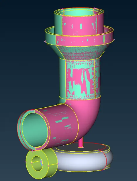 2 -->
2 --> 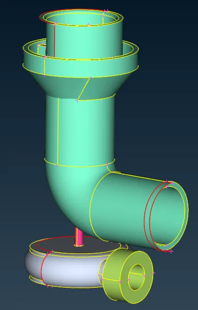 3 -->
3 --> 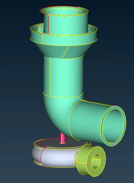
- The above image is the initial state of the turbocharger view it contains so much unwanted glitching first we have to eliminate the glitching so, click the DELETE option and enable PID MODE and then select the pink surface and then do the middle click and click ok to delete the pink surface.
- After deleting a surface the turbocharger model is looking like in the second picture without the pick surface. after that we needed to get the model like in the third picture so, we need to delete the extended surface present in the casing outlet.
- 1 -->
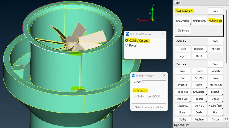 2 -->
2 --> 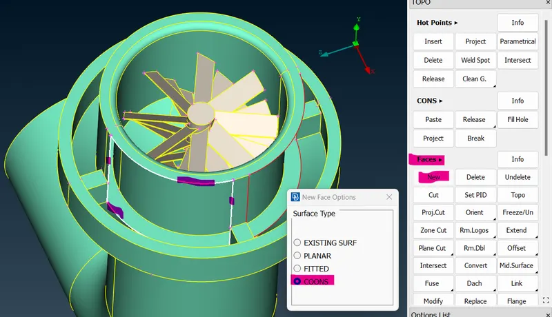 3 -->
3 --> 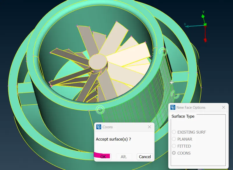
- Above image, to patch the surface hole by selecting the topo cleanup option in topo mode selecting the multiple project option in the hotpoints section and selecting the nodes to click the single cons line, and then doing a middle click to select cons and the Hotpoint is projected at the top. After that to patch, the hole so go to the new option in the face section and select the coons option in the new tab after selecting coons to select the single coon hole then do the middle and click ok for creating a new surface over there.
- 1 -->
 2 -->
2 --> 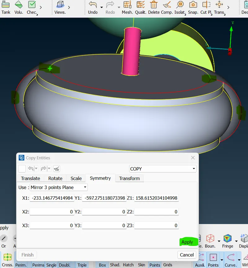 3 -->
3 --> 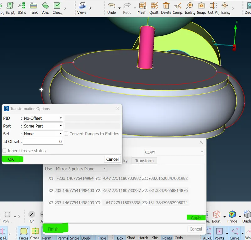 4 -->
4 --> 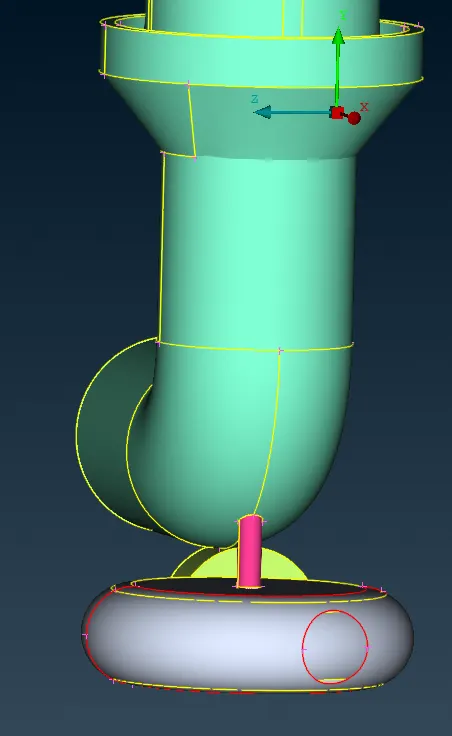
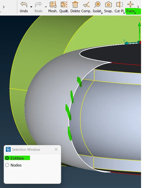
- Above image, To close the turbo casing click the TRANSFORM OPTION to select the copy option at the top bar of this screen and select the entities to click the highlighted surface in the first picture. And then do middle-click it and ask for the x1, x2, and x3 length so click the hotpoints present on the right side of the entities after selecting click apply and finish button. And after it asks to confirm the transform option so click ok. And now we got a closed surface created in that area. finally using the fill hole option to patch that hole.
- 1 -->
 2 -->
2 --> 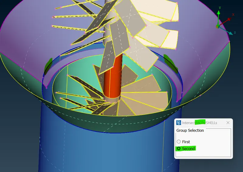 3 -->
3 --> 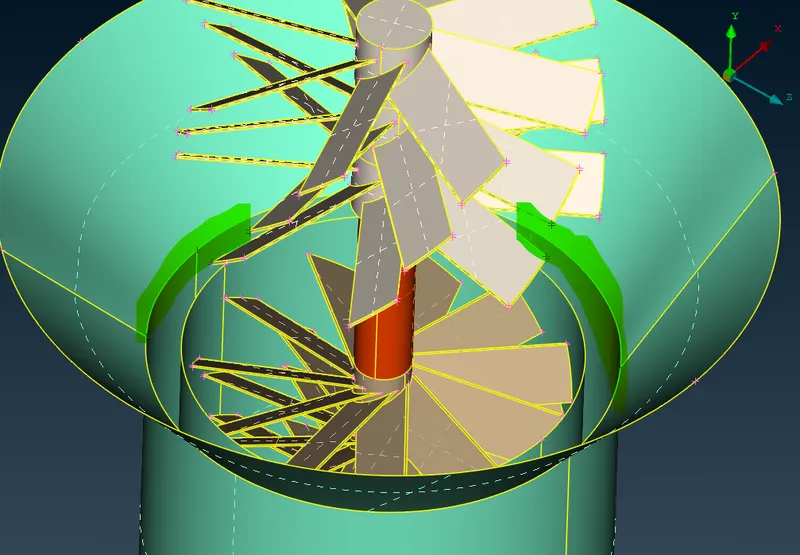 .
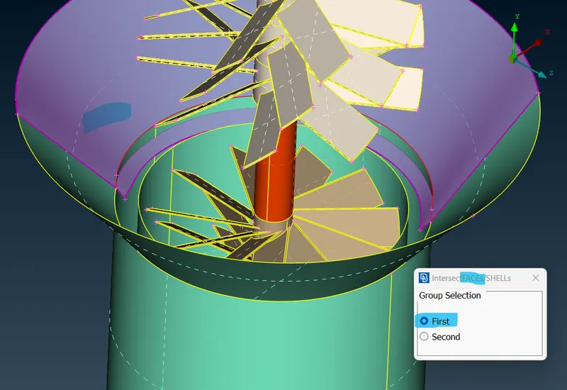
. - Above the image, there is a surface that has been penetrating each other. so, to delete that surface we needed to select the intersect option it asks us to select first so click the lavender color surface and do a middle click it asks us to select the second surface so select that blue color surface and do the middle click. after that, it got joined together.
- 1 -->
 2 -->
2 --> 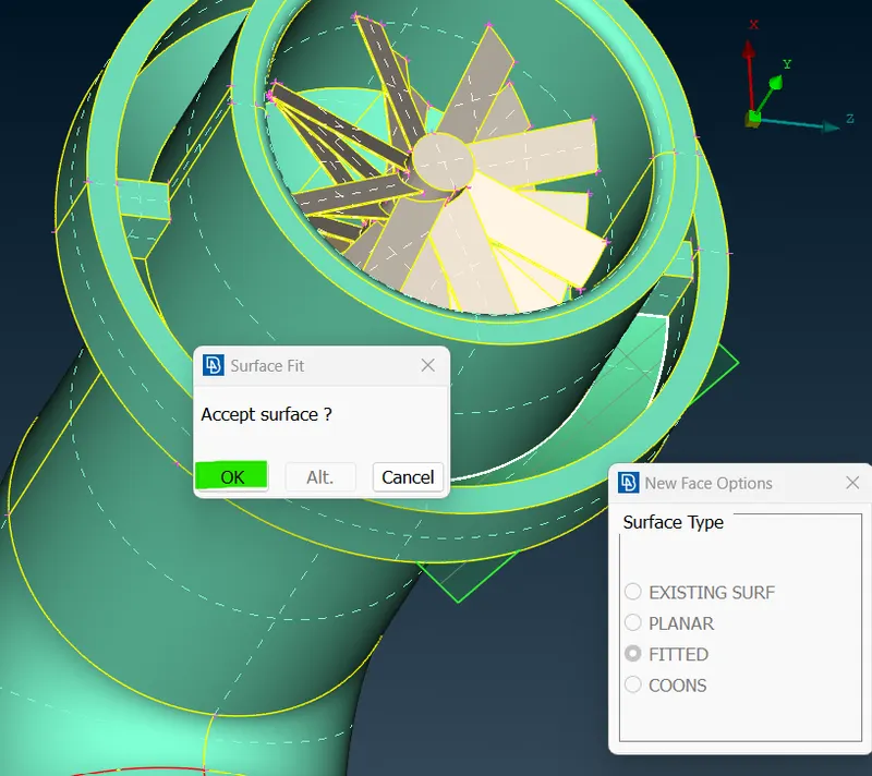
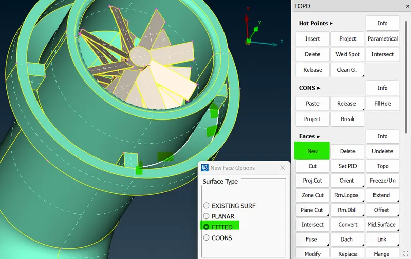
- Above image, To patch the hole to do click the new option in the face section and select the fitted option in the new mode. after clicking that option select that hole single cons lines and do middle click and click ok to create the surface. and similarly, repeat the same for reminding holes.
- 1 -->
 2 -->
2 --> 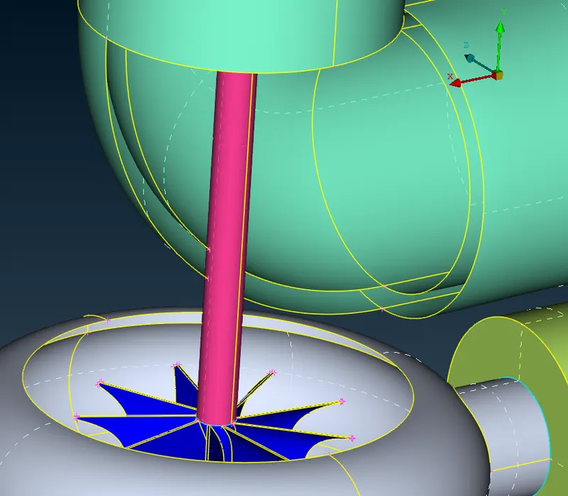
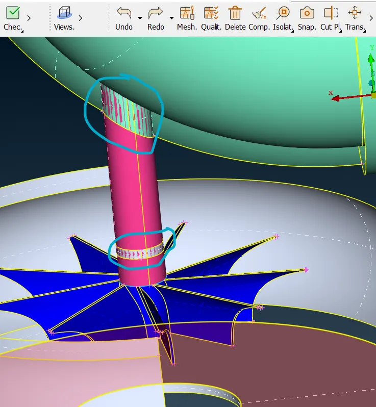
- Above image, In this shaft rotor, there is an overlapped surface presented so we need to delete that surface first to delete that surface go to the delete option select the overlapped surface, and then the middle click and click ok to delete the overlapped surface. and we got the output of the second picture.
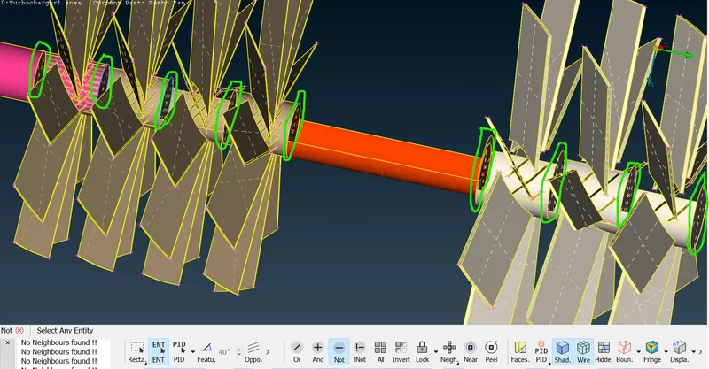
- In the above image, there is separation had been presented inside of the blade stage1 and blade stage2 and rotor. so we need to delete the green color circled part. so, go to the delete option select that circled part and do the middle click and click ok to delete the part.
- 1 -->
 2 -->
2 --> 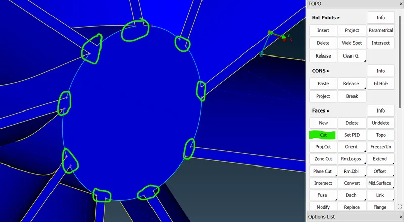 .
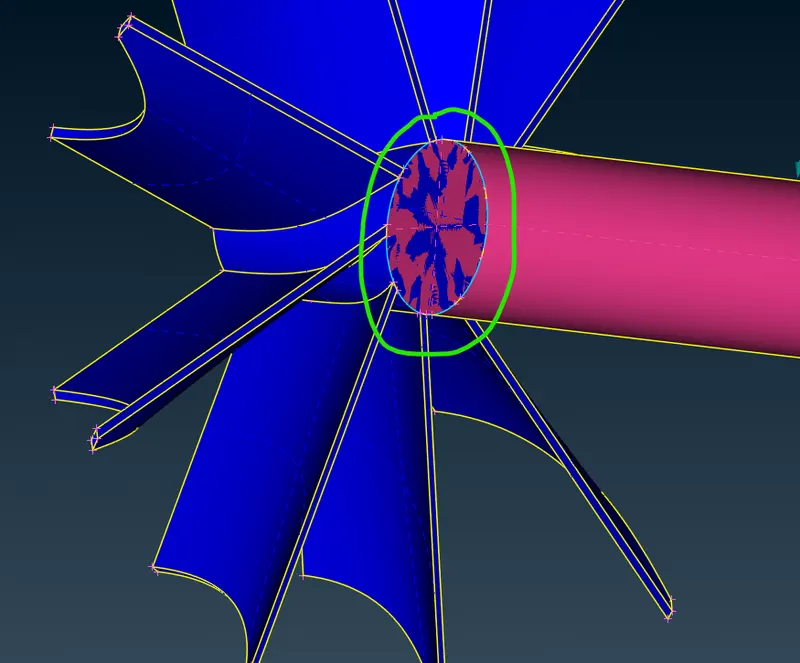
. - In the above image, there is a glitching present between the rotor and impeller so we need to delete that overlapped surfaces. and after deleting that surface. click the cut option in the face section and click the hotpoints circled in that image to join both hot points together. and delete that middle surface.
- 1 -->
 2 -->
2 -->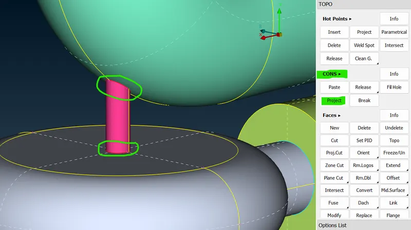 3 -->
3 -->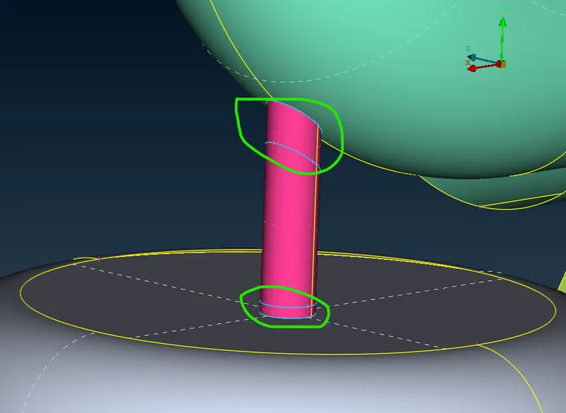
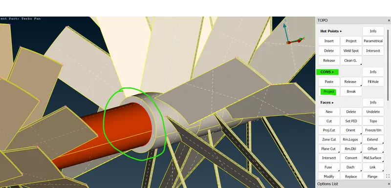
- In the above image, there are single cons presented between the blade stage 1 and the rotor. so to change that single con to double or triple cons select that topo option and drag to select that part and then middle click.
- 1 -->
 2 -->
2 -->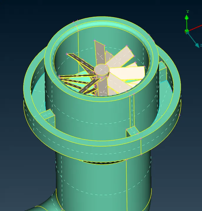
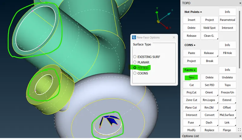
- In the above image, there is an open in that turbo casing inlet and outlet. and the compressor casing inlet and outlet. so we need to fix that in a closed manner go to the new option and select fitted and select that hole and that meddle click to create a surface. and then repeat the same for the remaining hole in the process.
- 1 -->
 2 -->
2 --> 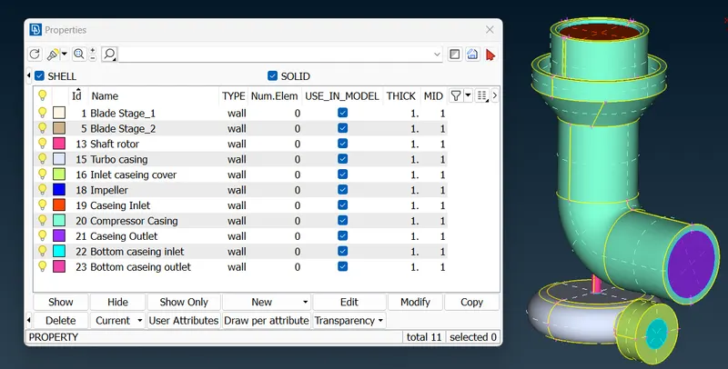
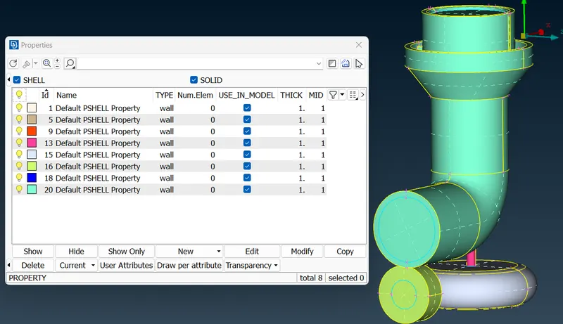
- In the above image, after the hole is closed we need to assign the PIDs for the inlet and outlet. so go to PID in that right-click to create a PID and enter the name of the PIDs. after that select that created PIDs and click apply and select the one inlet or outlet part and do a middle click to assign the PID. Repeat the same process for the remaining.
- 1 -->
 2 -->
2 --> 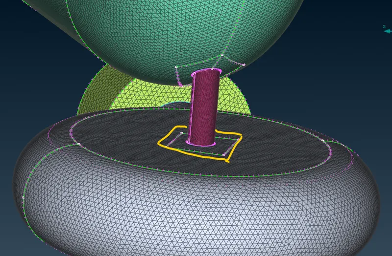 .
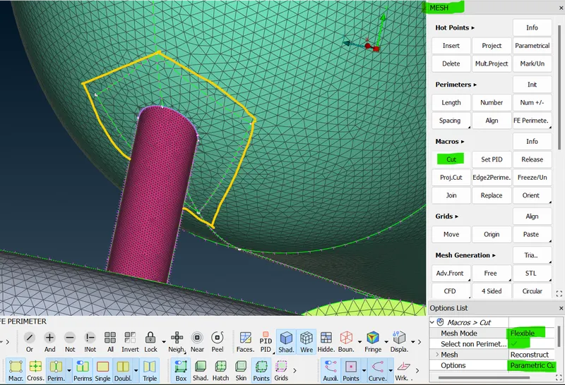
. - In the above image, to isolate the circled surface. so go to the cut option in the macro section and then select the parametric cut and enable the flexible cut and go to model click the Hotpoint and place somewhere in that surface and join the four lines together. repeat the same for the turbulent casing. so here topo clean-up part is over.
- 1 -->
 2 -->
2 --> 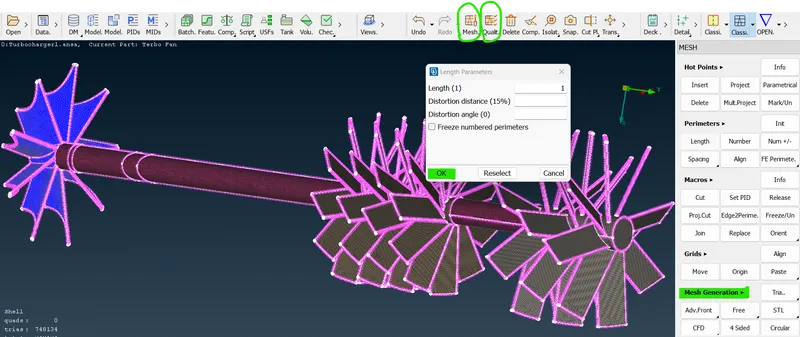 3 -->
3 --> 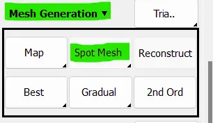 4 -->
4 --> 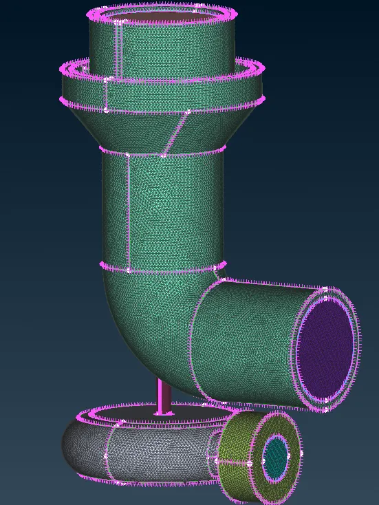
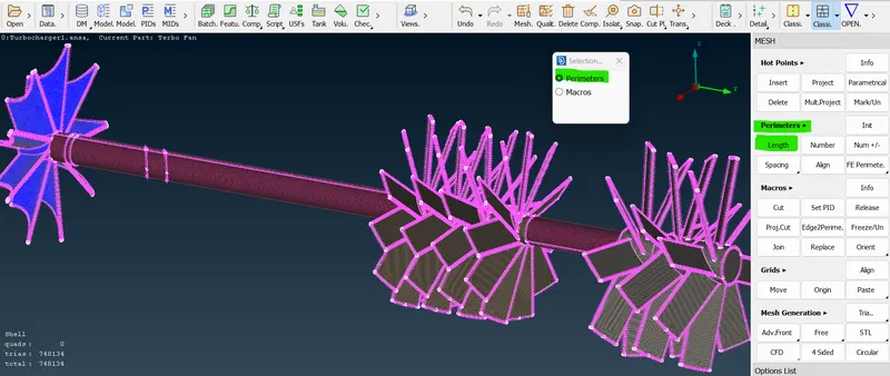
- In the above image, there is surface meshing is happened so, now we are going to surface meshing part so select the component first and then click the length option in the perimetric section then it asks for the length of the component and macro so that select and enter the value and click ok. now go to the quality criteria button and enter the min and max target length value click ok. and click the mesh button after that enter the value and min target length now go to the mesh generation section select the spot to mesh to visible and now the component has meshed. And repeat the same process for the remaining components.
- 1 -->
 2 -->
2 -->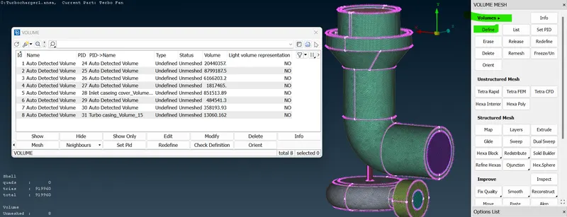 3 -->
3 -->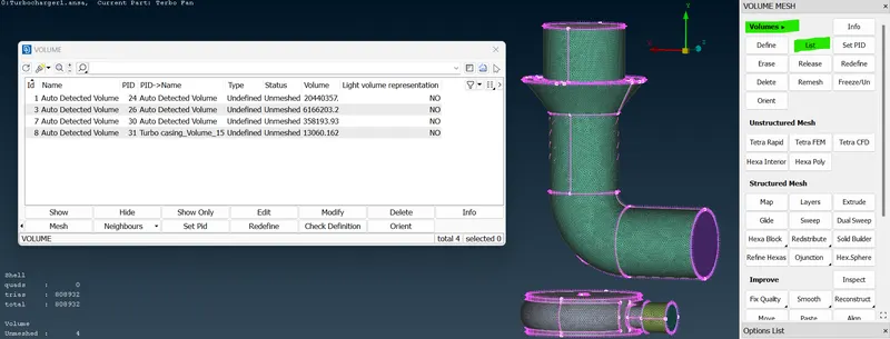 4 -->
4 -->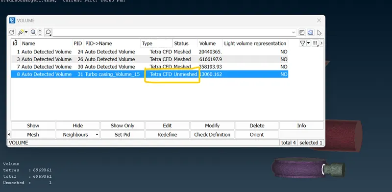 5 -->
5 -->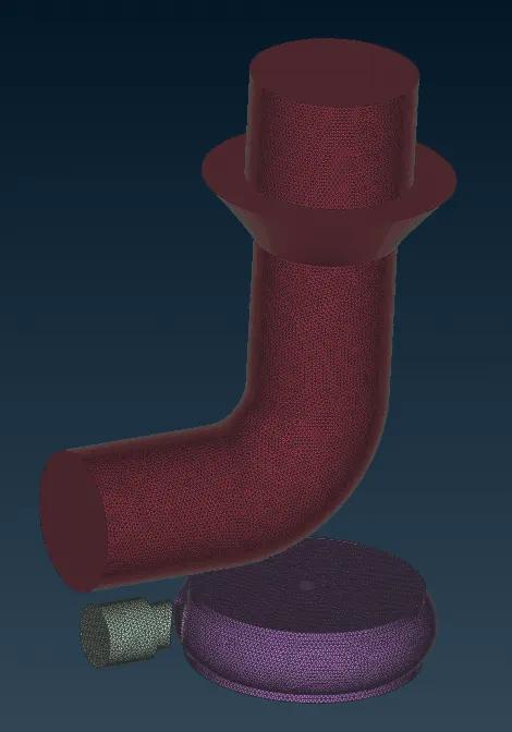 6 -->
6 -->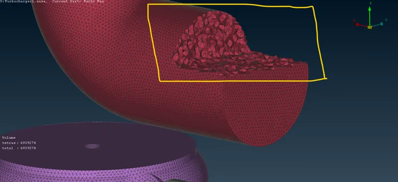 .
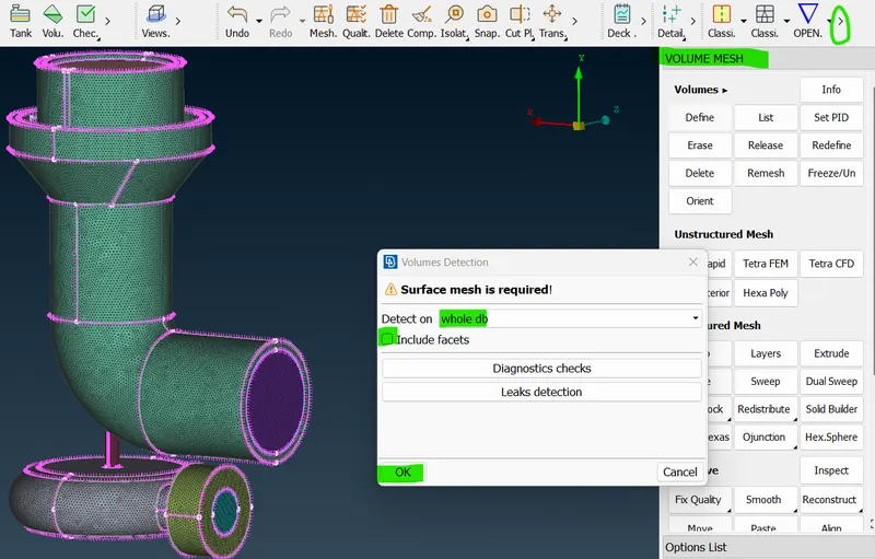
. - In the above image, to select defined in volume mesh --> Auto Detect option --> select whole database (DB) in auto-detect -> click ok.
- now the volume mesh pop-up is showing an autodetected volume and undefined meshed.
- so, select the undefined mesh one by one right to select re-mesh-> select volume type -> click tetra CFD type ->ok -> now the status has meshed.
- and then similarly repeat this process if any elements are unmeshed.
- now the entire model gets volumetric meshed.
- click the "NOT" option -> select ENT mode -> box selected in a model to see a tetra element.
LEARNING OUTCOME:-
- So, as of now, I learned how to topo clean-up and mesh the surface and volumetric mesh for this turbocharger
RESULT:-
- Hence, the Turbocharger model had been successfully done with mesh and surface mesh, and volumetric mesh.
CONCLUSION:-
- Finally we concluded here, so I learned many options and operations of the button and with help of those buttons I learned how to sort this model.