Week 4 Challenge : CFD Meshing for BMW car
LINK:- https://drive.google.com/file/d/1gSSvqMyjLlCxSpMG-AuWjpBP8CRATpK-/view?usp=drive_link
AIM:
We needed to check and solve all geometric errors on the half portion for the BMW car model, assign appropriate PIDs, and perform meshing with the target length and element quality criteria. once did this process we need to symmetry the other side.
PROCEDURE:
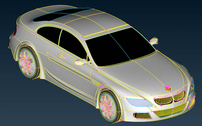
- So, in this BMW car model there are a lot of single cons and overlapped surfaces are presented in this model. so, first, we need to check the BMW model is present in single cons. If the model contains single cons then click the Topo option and select the entire car model click. now it converted into double cons.
 =>
=>  =>
=>  =>
=>  =>
=>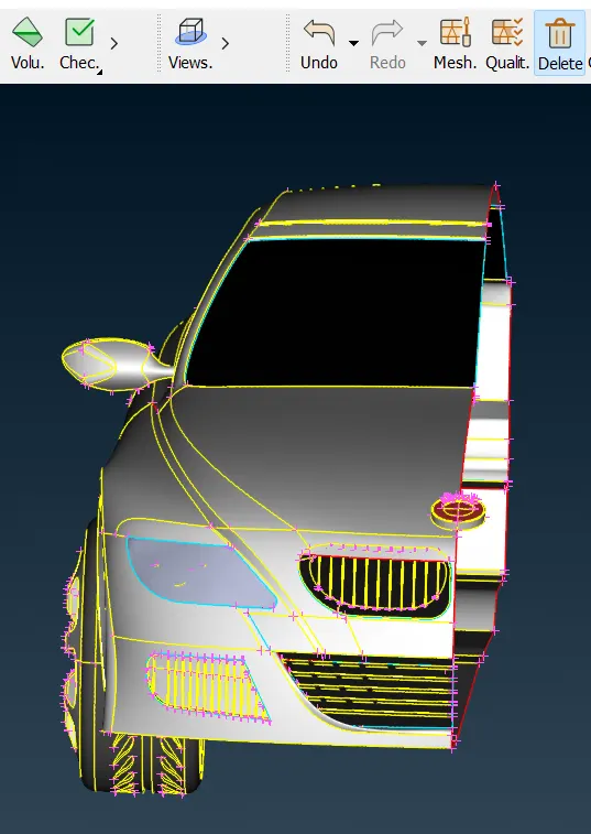
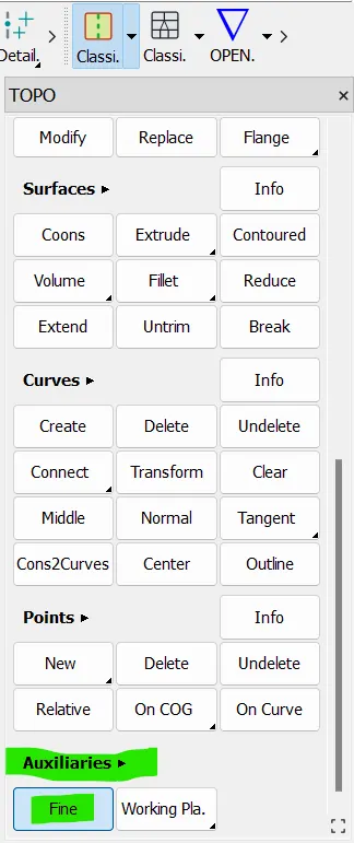
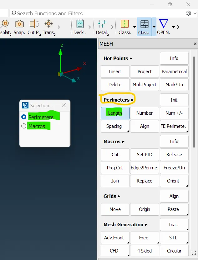
- Now this car has an unstructured exterior outlook. so for that, we need to use the "Fine option". so, this option is taking so much time to get the defined shape. so, instead of this fine option, we used the length option and now we can very well get the shape of the car.
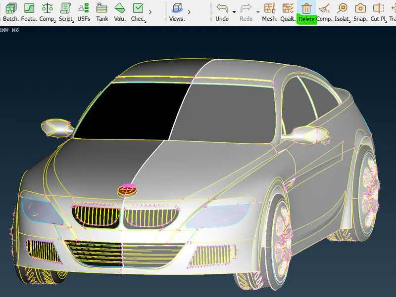
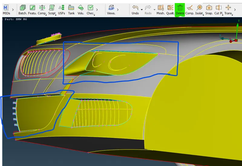
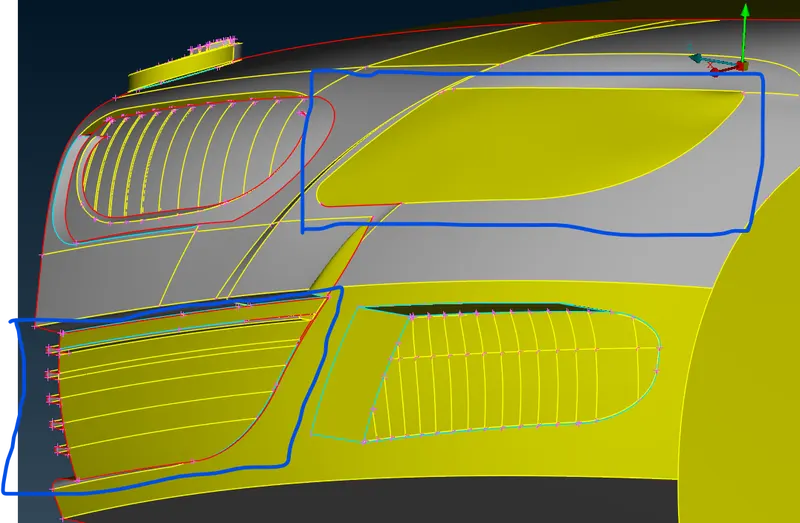
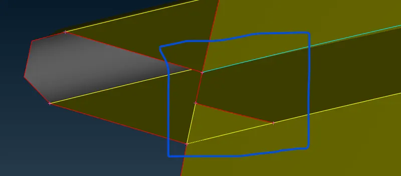
- This model has pretty much symmetry on another side. apart from every feature retaining all the features are pretty much symmetry. so, now we used the universal delete option for deleting half of the model so select half of the part that has been deleted. so, the remaining half part is here we need to correct that model, and after that, we will reflect the half side to the other side by using and symmetric option.
 =>
=>  =>
=>  =>
=> 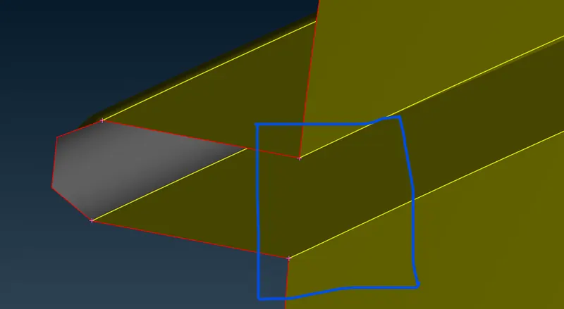
- So, before correcting that model the adjanda is we get to create a few volumes inside this main car and then the four tires and we will create the wind tunnel so the volume is between a car and the wind tunnel. we need to consider the outside surface of the car. so, that we will check the single cons and triple cons one by one.
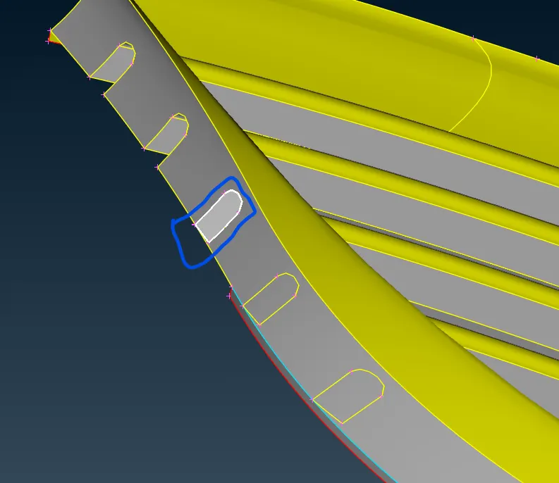
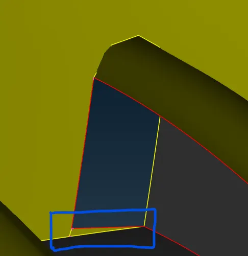
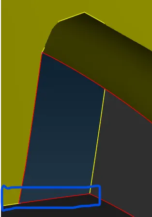
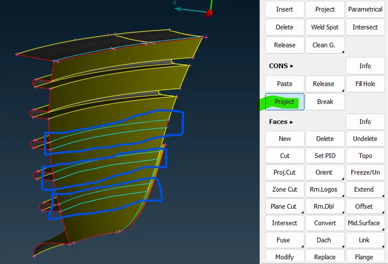
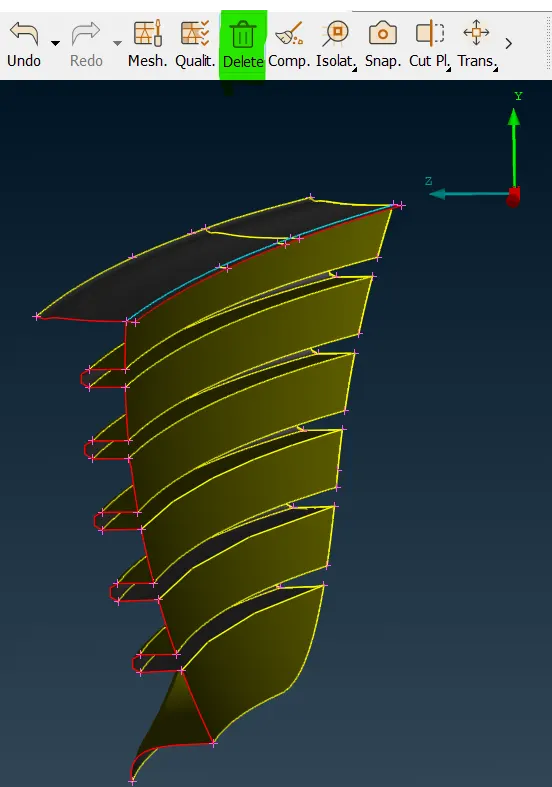
- And also we need to delete the unnecessary feature inside the car. so, the triple cons are deleted and double cons are created in that place.
 =>
=>  =>
=>  =>
=>  =>
=>  =>
=> 
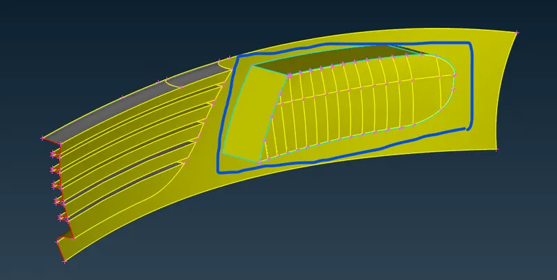
- We don't have the outer surface of the triple cons and that front surface. so, delete that surface we don't need that instead of that surface we will create another surface using the Somme option.
 =>
=>  =>
=>  =>
=>  =>
=>  =>
=> 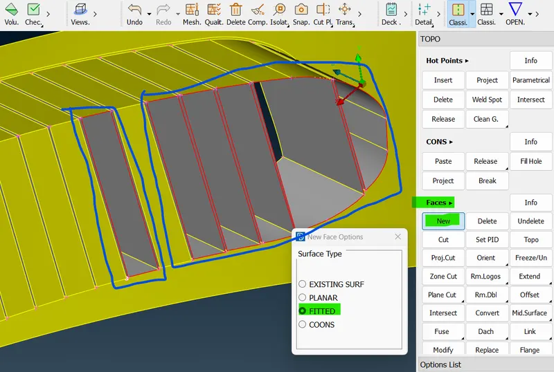
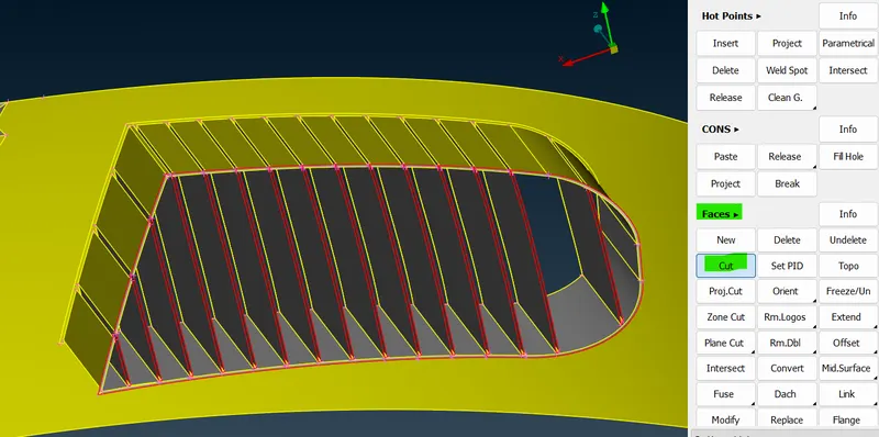
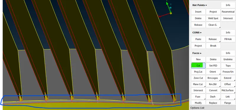
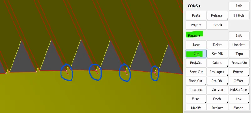
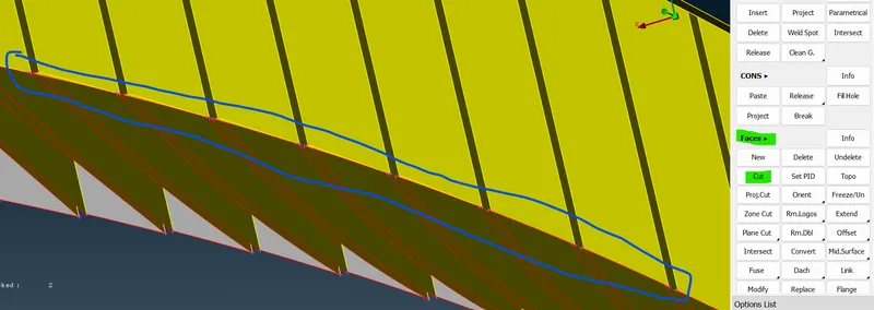
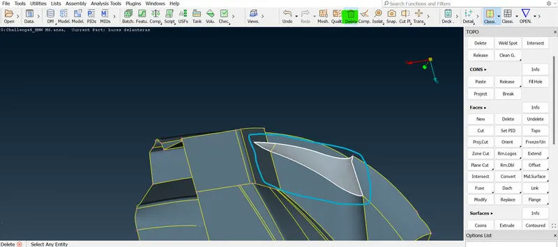
- And few surfaces are curved in nature. so, we use the "cut option" and "Delete option" to recreate the surface. This is how we have done the particular fins and our particular grill part. and you can see there aren't single cons apart from that end surface.
 =>
=>  =>
=>  =>
=>  =>
=>  =>
=>  =>
=> 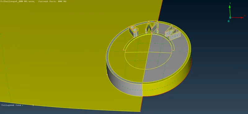
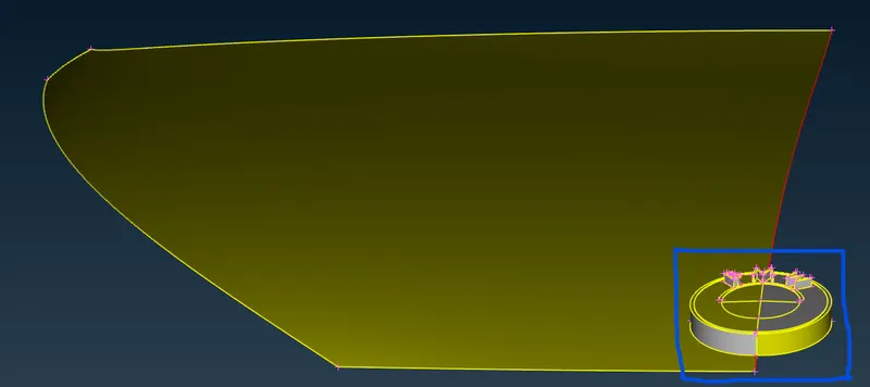
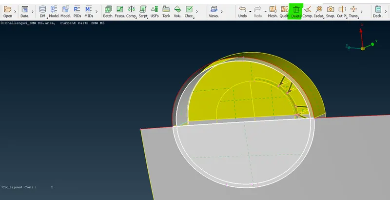
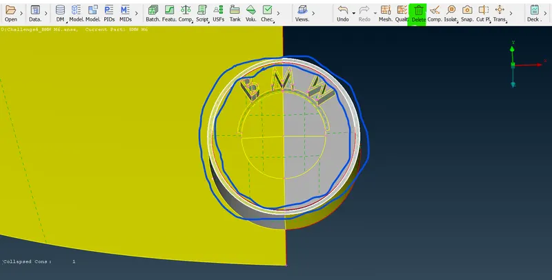
- Now we will start working with this particular region like the BMW logo and below that air went inlet there is a triple presented inside. so, we will need to solve that into single cons.
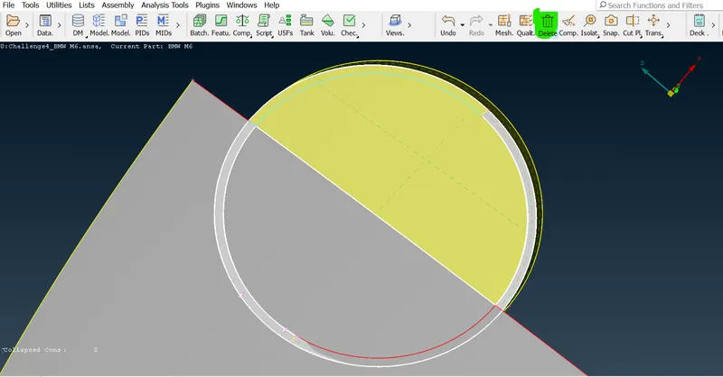
- First we need to surface the BMW logo and that surrounding surface using the "iNOT" option and use the "Lock" option to lock the isolated part. now delete the unwanted triple cons and the surface presented in that logo.
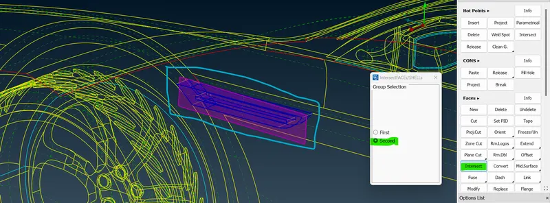
- Click "Intersect option" ->select the backside of the BMW logo of the surrounding surface part first ->then middle click -> select the second part of the BMW logo of the surrounding part and then middle click -> now delete the unwanted surface part and keep remains.
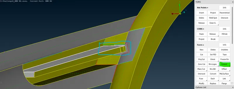
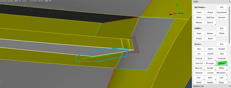
- Now if it is not deleted that surface uses this "Extend option" in topo mode and then clicks the line or selects the line and does a middle click. now try deleting the unwanted surface like overlapped surfaces.
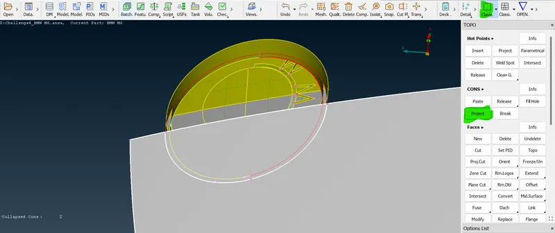
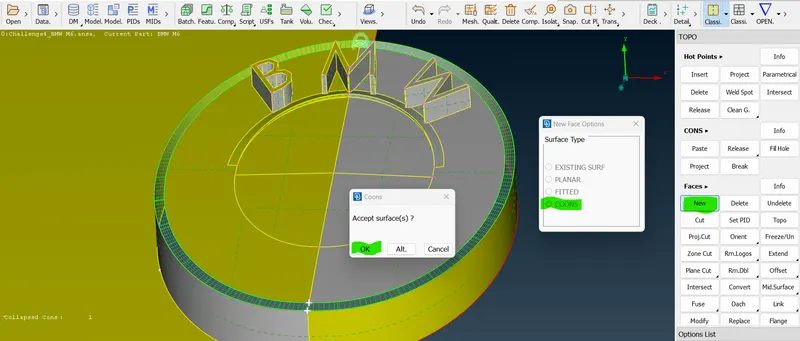
- Use the TOPO option to get the correct cons and delete the bottom surface and then use the "extend option" to extend the surface. now the triple cons have been formed. so, now we can delete the inside surface. And deleted the outer ring also and to patched the surface using a new option.
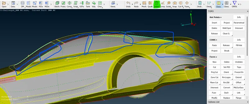
- Now in that windshield, there is a triple presented the agenda will be to remove the unwanted triple cons then try deleting the extended surface. in some way, there are two different components one is the outer side and the other one is the inner side. so, we don't want the inside surface. If I delete that the triple cons will be gone from there.
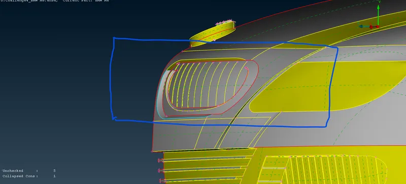
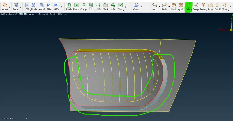
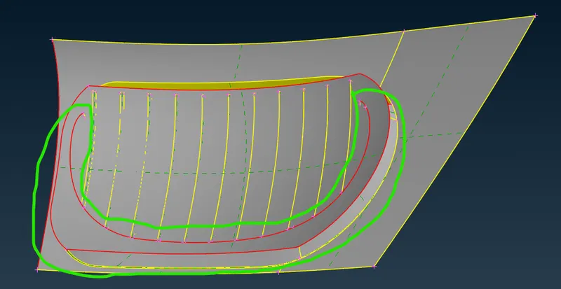
- Similarly I have removed the unwanted triple con surface on that rear side and made my body triple cons free and single cons also.
 =>
=>  =>
=>  =>
=>  =>
=>  =>
=>  =>
=>  .
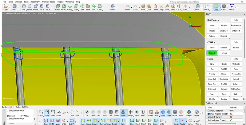
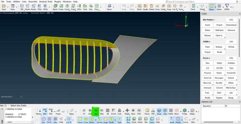
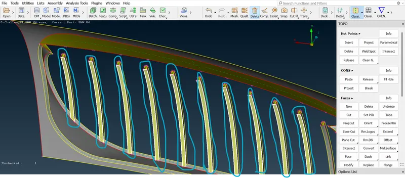
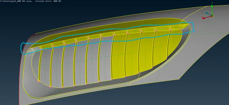
.- As we have discussed there should not be any surface inside any volume. so, in that grill part, there are no surfaces present inside there should be a single surface. so, the "iNOT" option selects that grill part region and then middle click and lock that part region using the "Lock option".
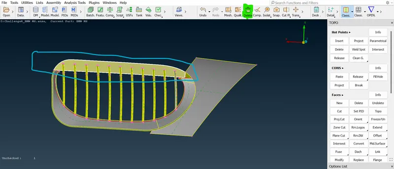
- Now, first delete the unwanted surfaces presented in the current region. so let's delete that first. now, select that single cons in the front grill part and a project that single cons to the grill part's back side surfaces.
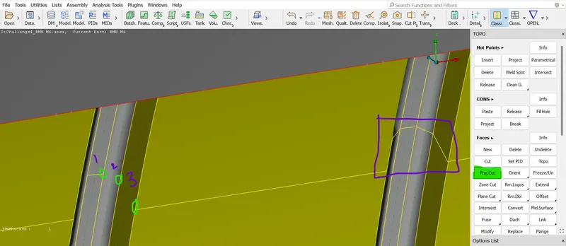
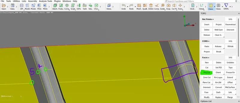
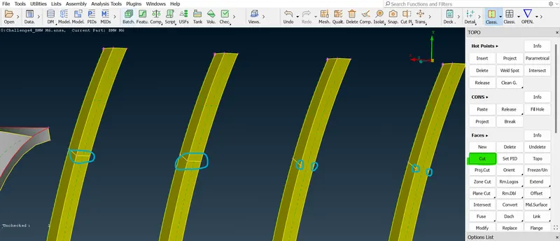
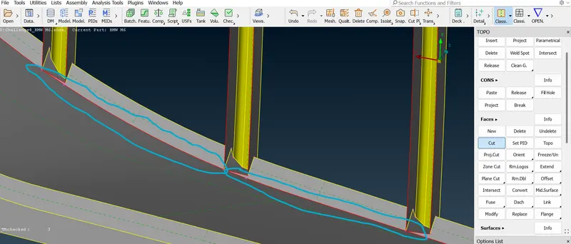
- To cut the upper side grill region part use project cut option in the face section first select the project cons and hot points after selecting that and click on the next cons line either left or right.
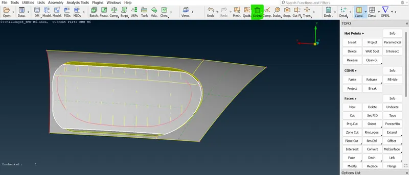
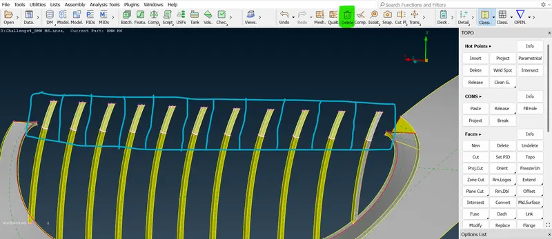
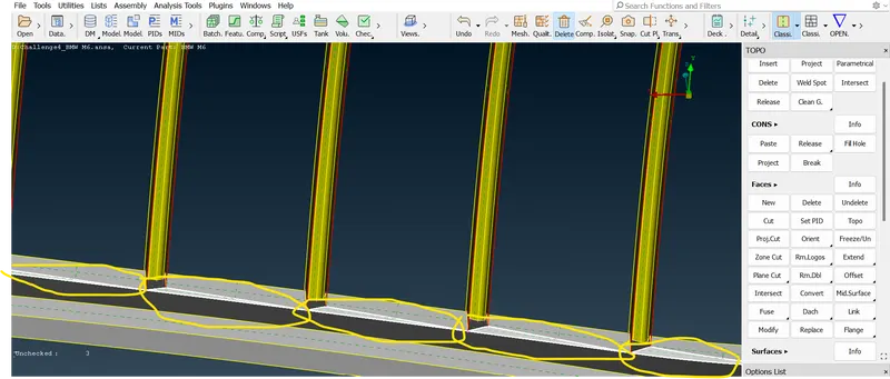
- Now, to delete the front side of the gill part after projecting the cons from end to end side now delete that face using the delete option after deleting the back side of the grill surface and also delete as well as grill parts like in that grill we applied cut already not cut that surface part.
 =>
=>  =>
=>  =>
=>  =>
=>  =>
=>  =>
=>  =>
=> 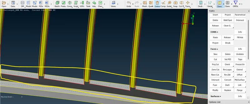 .
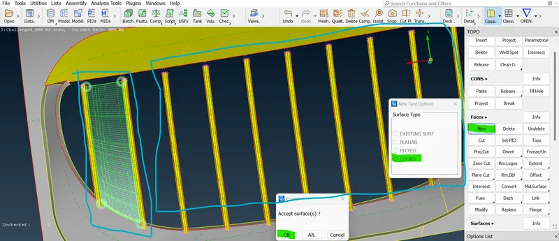
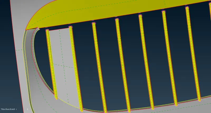
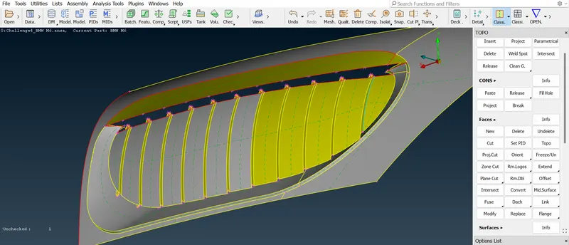
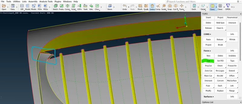
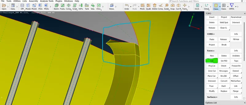
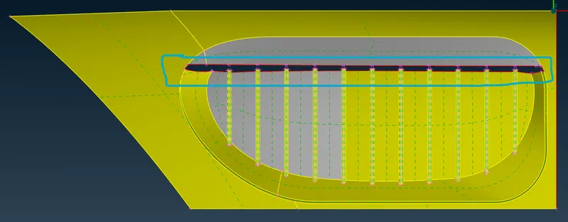
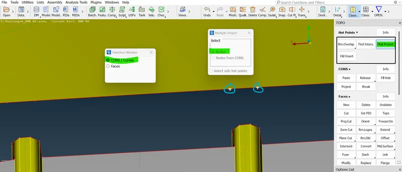
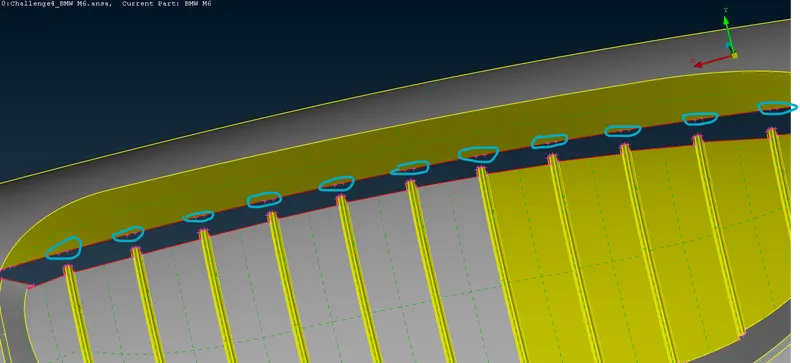
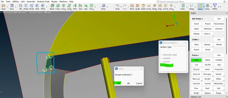
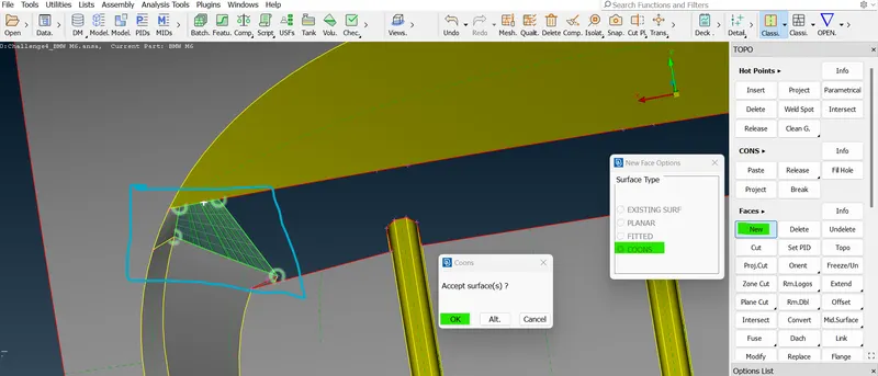
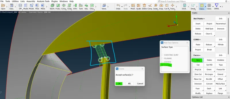
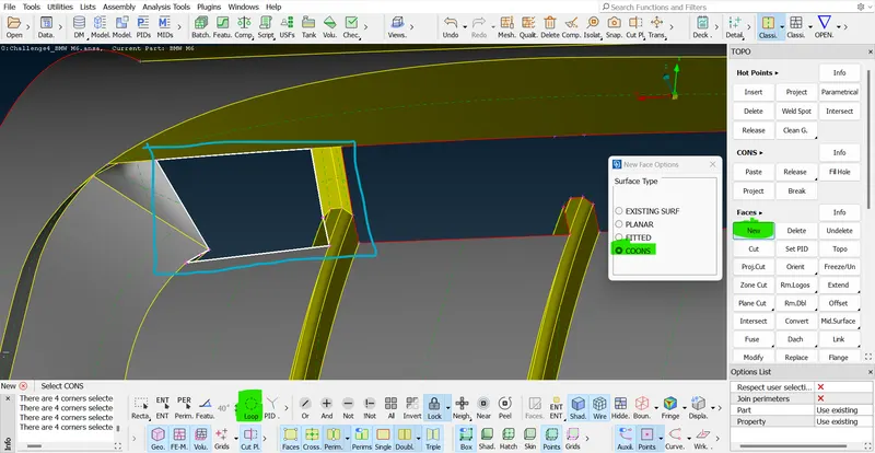
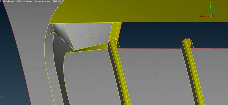
.- In this location the horizontal flat surface is located where it is intersected in between the plan. but the thing is here the intersection is not done properly so, now we have to intersect that properly and then delete that unwanted surface after intersecting that region.
 =>
=>  =>
=>  =>
=>  =>
=>  =>
=>  =>
=>  =>
=>  =>
=>  =>
=>  =>
=>  =>
=>  =>
=>  =>
=>  =>
=>  =>
=>  =>
=>  =>
=> 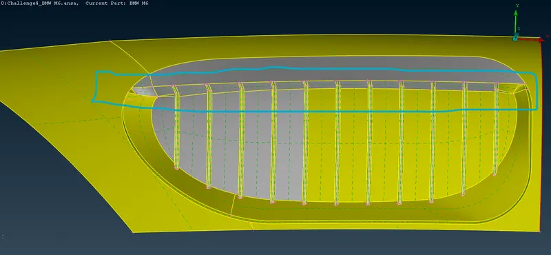 .
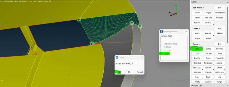
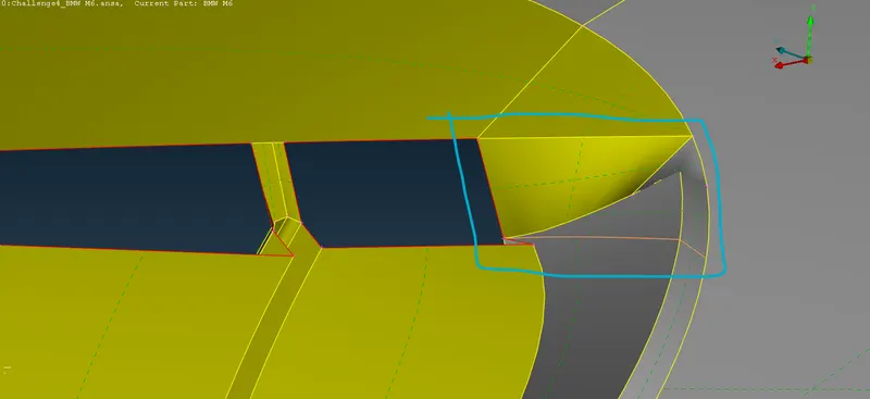
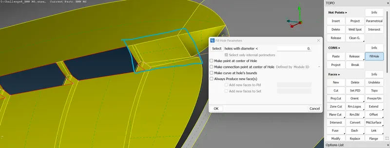
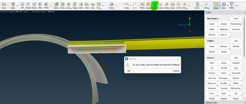
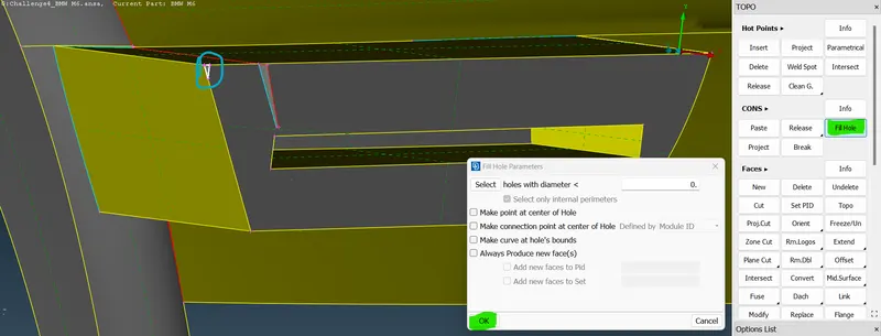
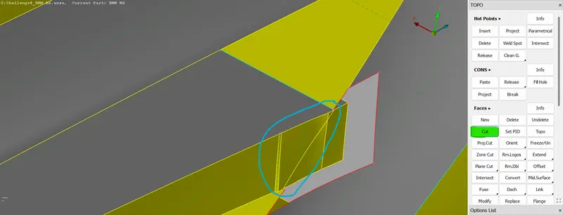
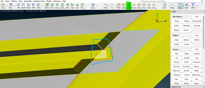
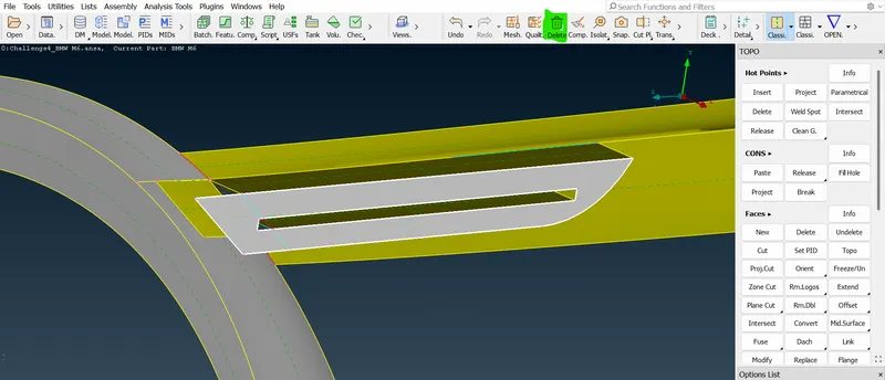
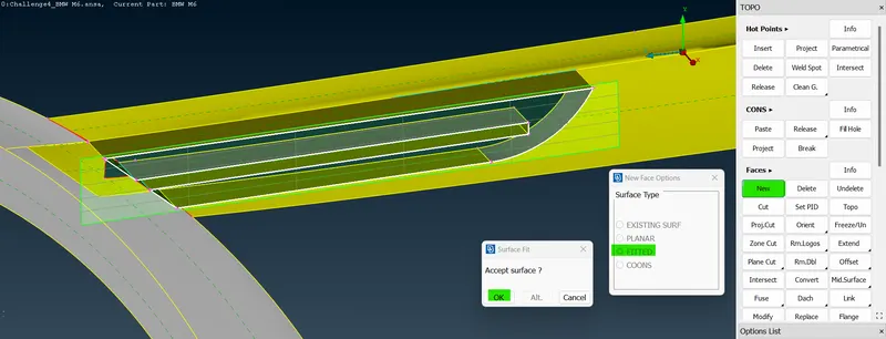
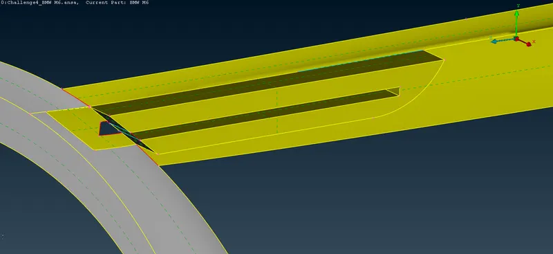
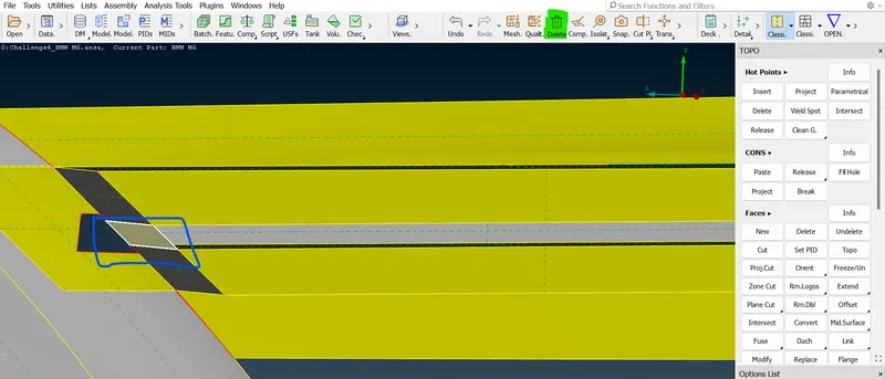
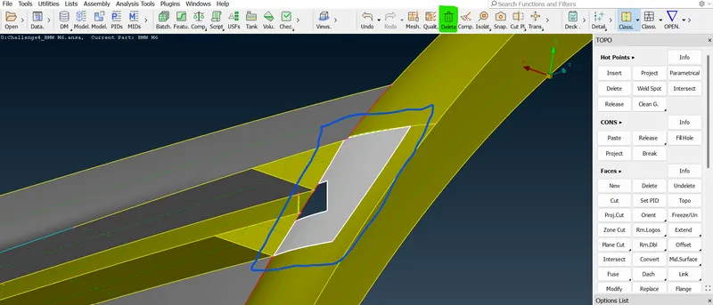
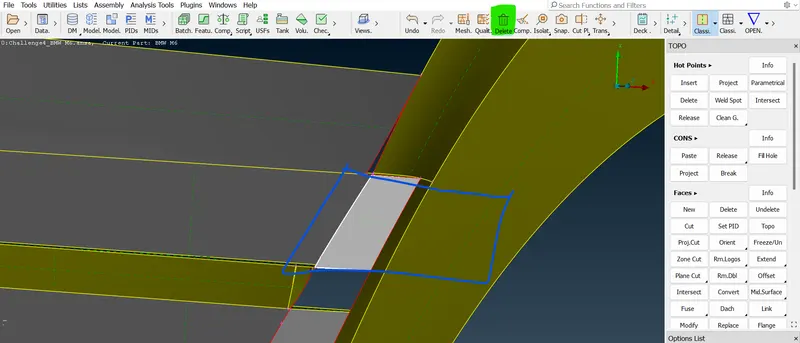
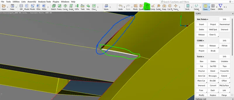
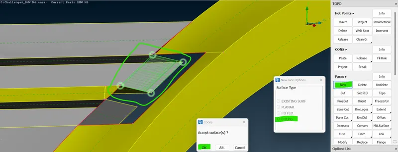
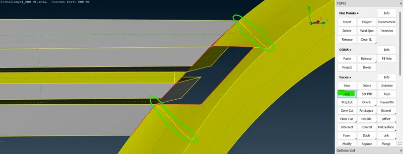
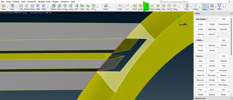
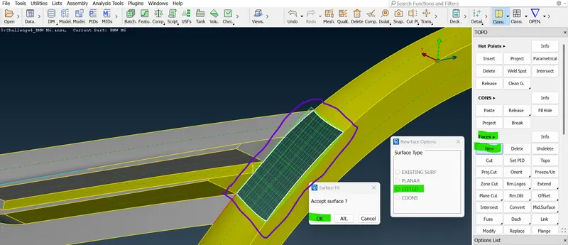
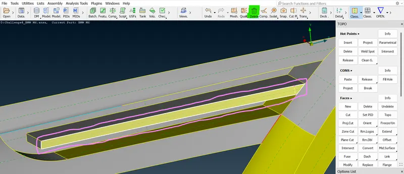
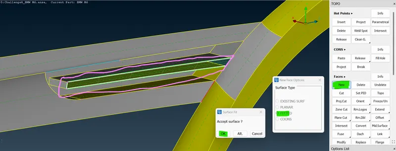
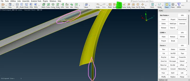
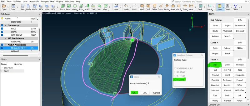
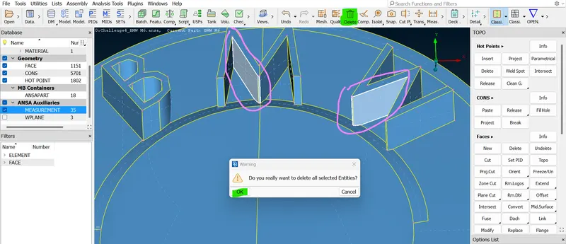
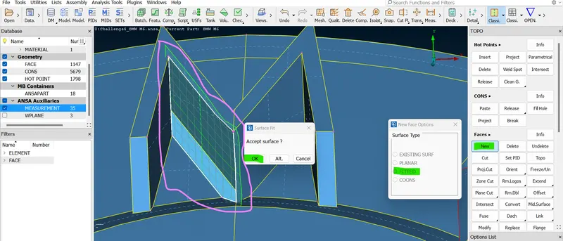
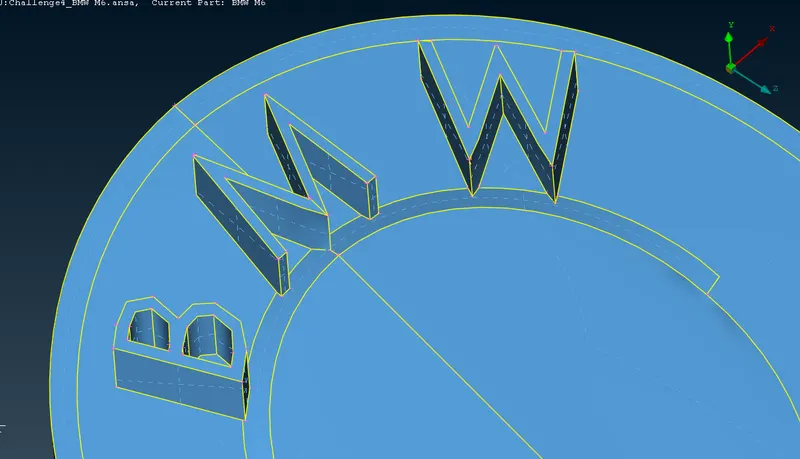
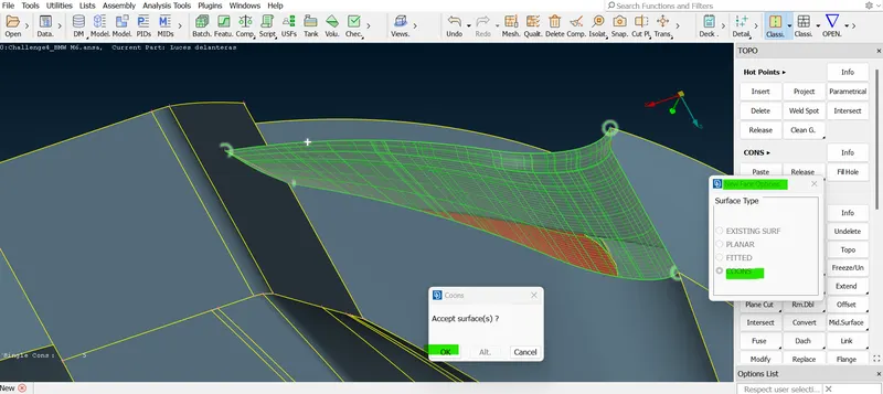
. - As we have discussed there should not be like surface inside any volume. so, in that grill part, there are no surfaces present inside. there should be a single surface. for this criterion, we need to do some topo cleanup. so in the above images simply we are some deleting the surface and recreating the surface using some tools like " Delete option, new coons options, cut option, and fill hole option " For isolating the surface we need to use some boolean options like "OR, AND, NOT, iNOT options". so, finally, a new surface is created.
 =>
=>  =>
=> =>
=>  =>
=>  =>
=> =>
=> =>
=> =>
=> =>
=>  =>
=> =>
=> =>
=> =>
=> =>
=> =>
=>  =>
=> =>
=> =>
=> =>
=> =>
=>  =>
=>  =>
=> 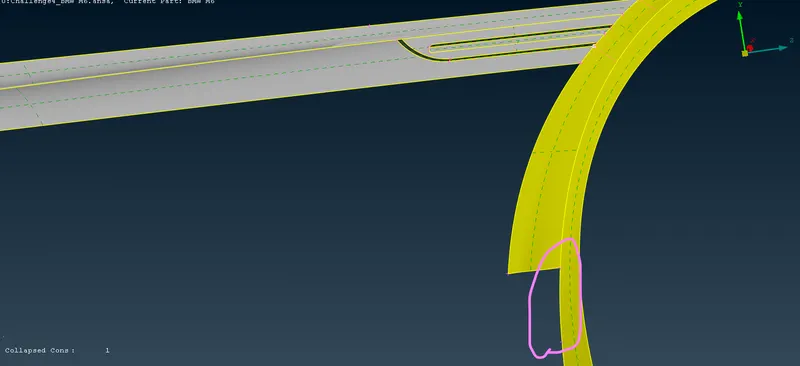 .
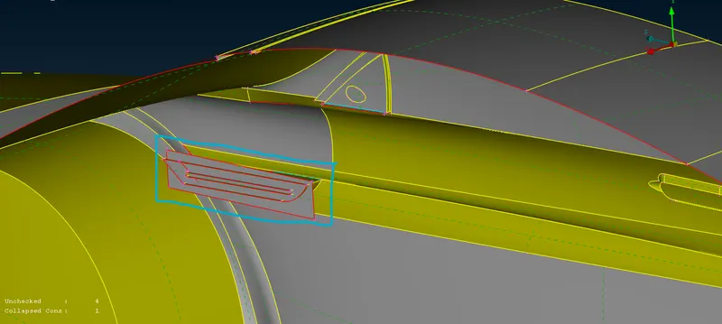
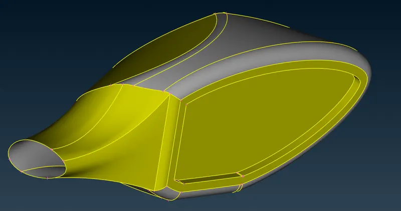
.- As we have discussed there should not be any surfaces inside any volume. so actually there is a volume in that side panel so we need to rectify the using tools like "Extend option, interset option, delete option, cut option, and past option" and some boolean operations are "AND, iNOT, OR, NOT, LOCK options" these are used to delete and recreate the surface.
-
 =>
=>  =>
=>  =>
=>  =>
=>  =>
=>  =>
=> 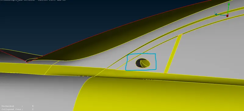 .
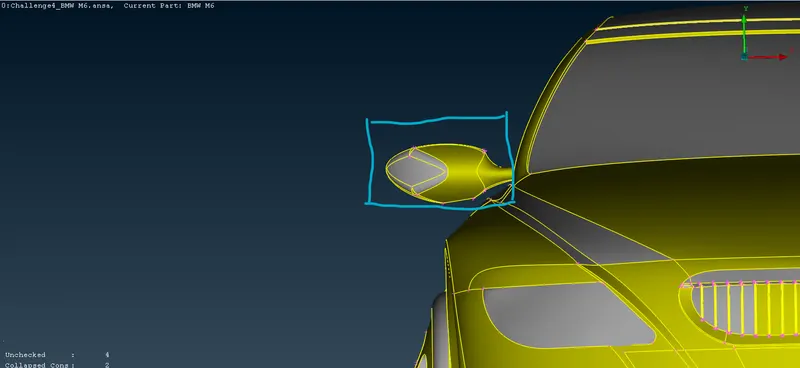
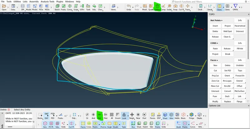
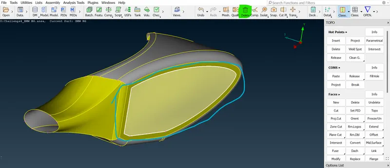
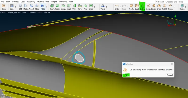
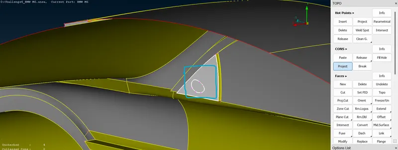
. - As we have discussed there should not be any surfaces inside any volume. so actually there is a volume in that side mirror view. In that side mirror, there is a surface present into this mirror. so we need to rectify the using tools like "Extend option, interset option, delete option, cut option, past option" and some boolean operations are "AND, iNOT, OR, NOT, LOCK options" These are used to delete and recreate the surface.
 =>
=>  =>
=>  =>
=>  =>
=>  =>
=>  =>
=>  =>
=>  =>
=>  =>
=>  =>
=>  =>
=> =>
=> =>
=>  =>
=>
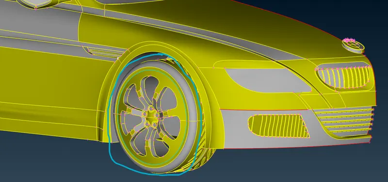
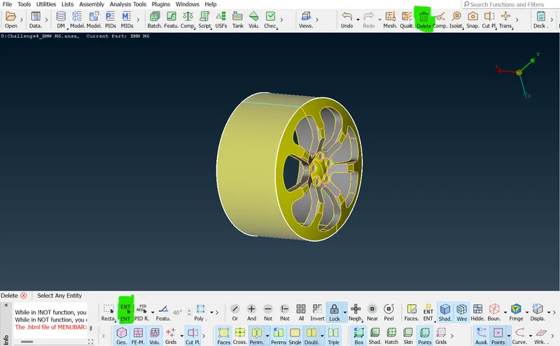
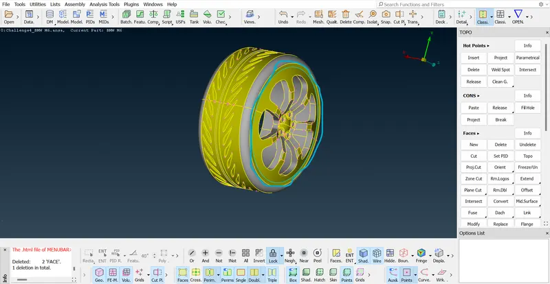
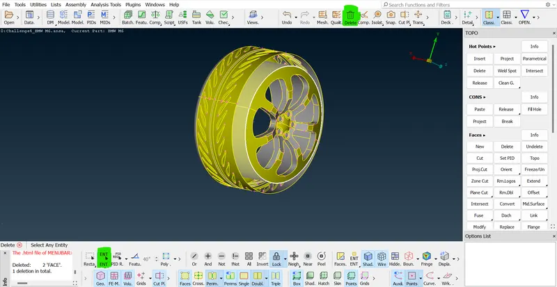
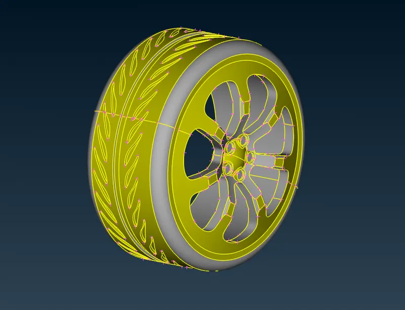
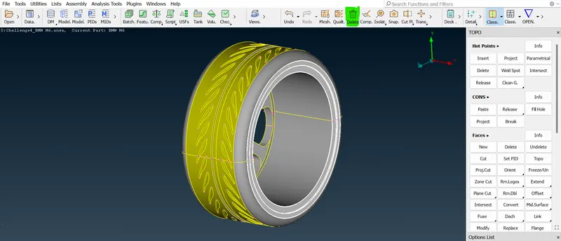
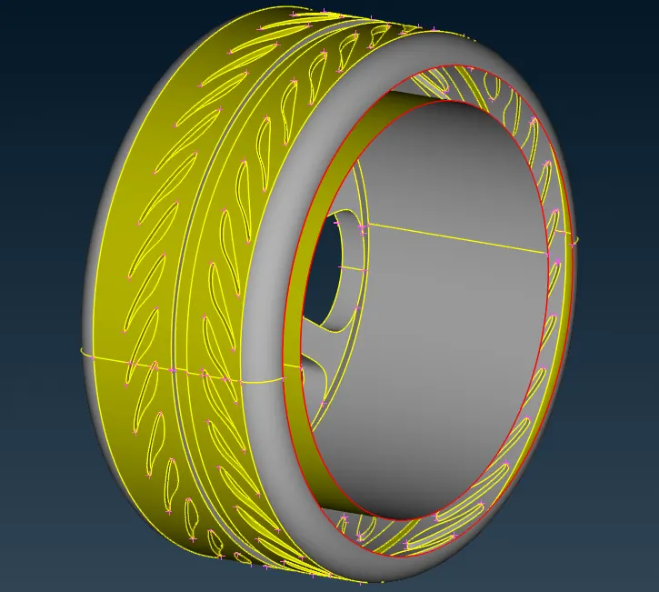
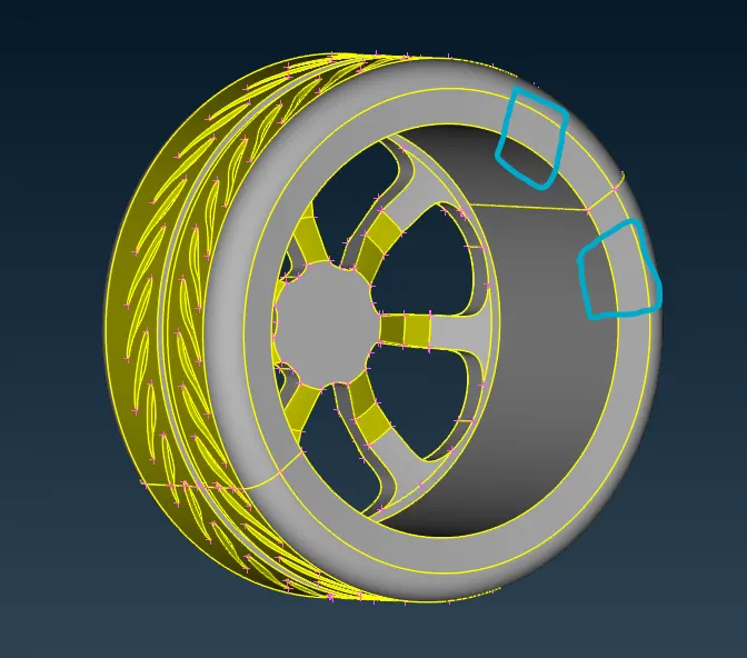
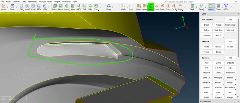
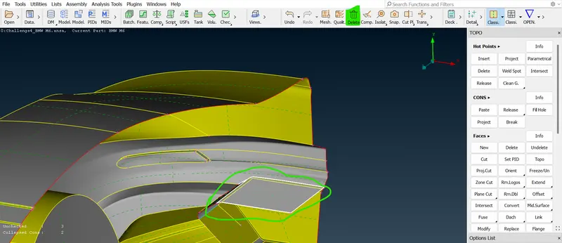
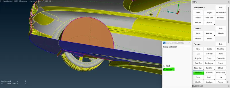
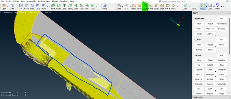
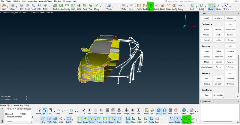
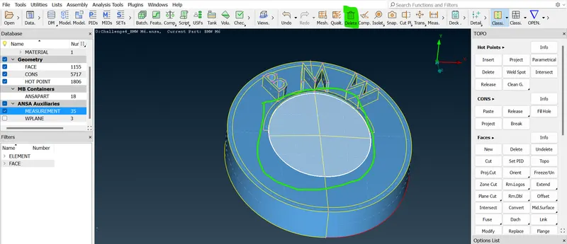
- In this car tires there is a volume presented into the tires. the four tires will have four volumes and the car will have a fifth volume. so, there is 5 volume. so, we need to delete and keep one volumetric mesh of the wind tunnel.
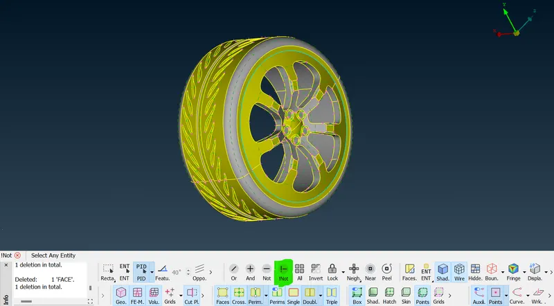
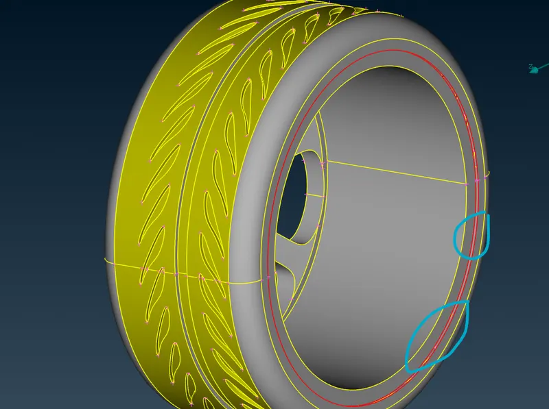
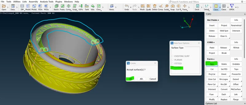
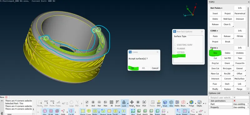
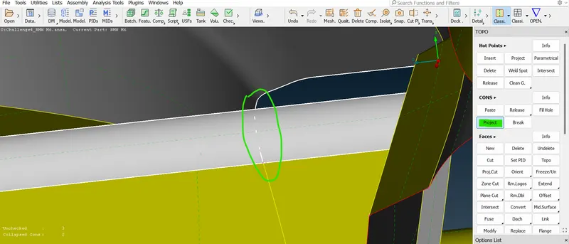
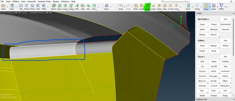
- So first isolate the tires part alone Lock that part and first hide the outer region of the tire and now we can see the triple cons are connected with some surface we don't want that surface actually
 =>
=>  =>
=>  =>
=>  =>
=> =>
=>  =>
=> 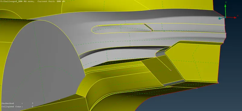 .
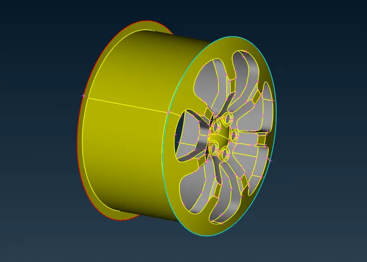
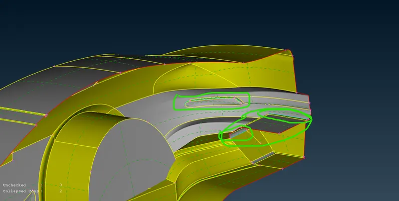
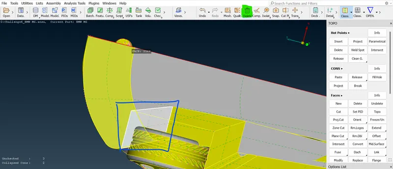
.- Now the triple cons are cleared by deleting some triple cons inside of the part. so, if you don't see any triple cons that mean hollow from the inside then you will have a common volume or single cons are getting cleared now.
 =>
=>  =>
=>  =>
=>  =>
=> =>
=> =>
=> =>
=> =>
=>  =>
=>  =>
=> =>
=> =>
=> =>
=>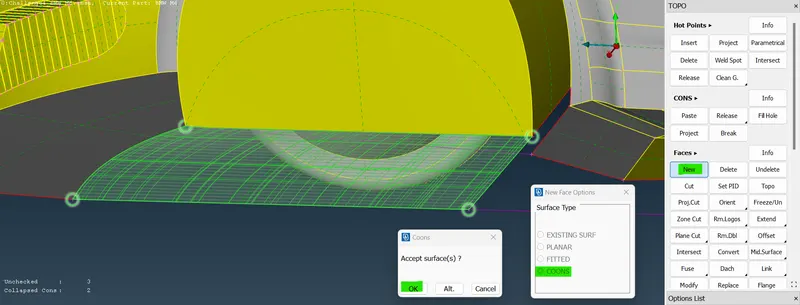
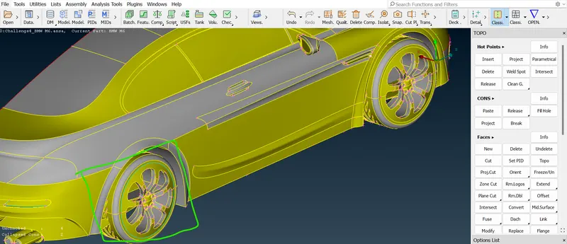
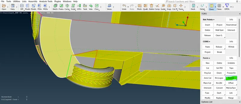
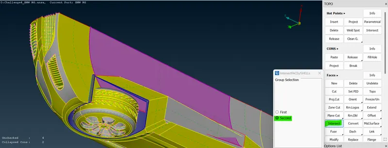
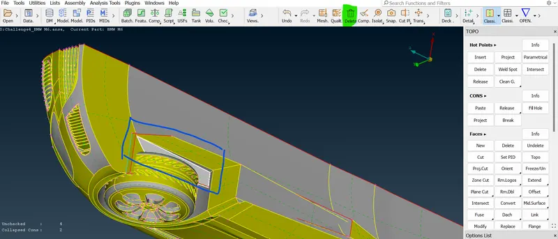
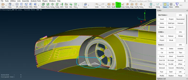
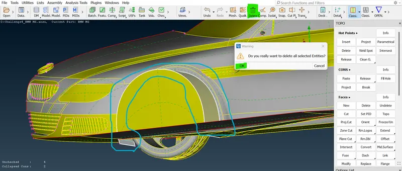
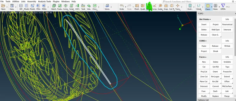
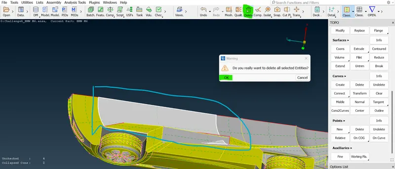
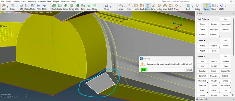
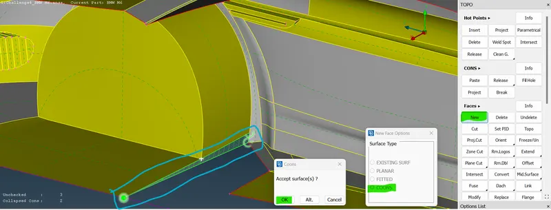
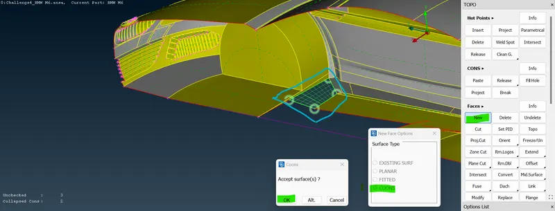
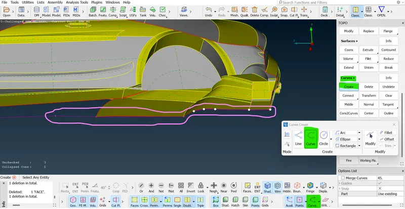
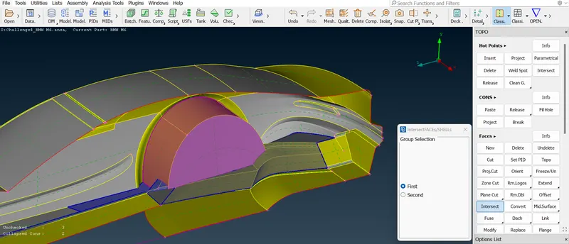
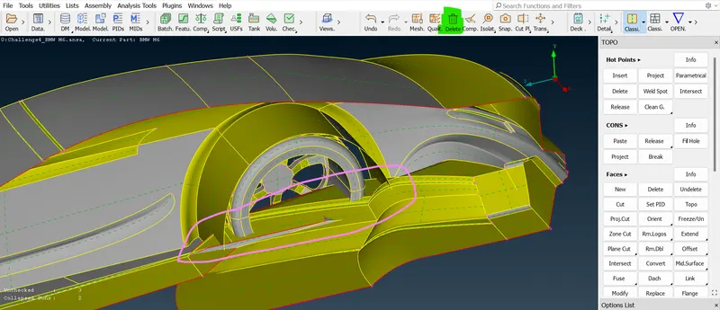
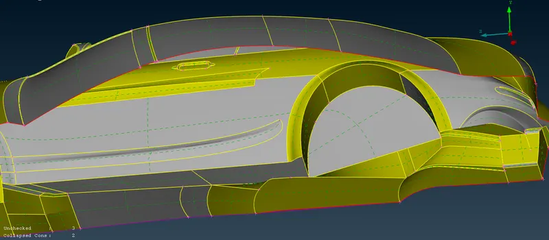
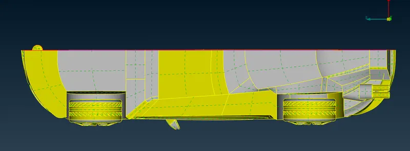
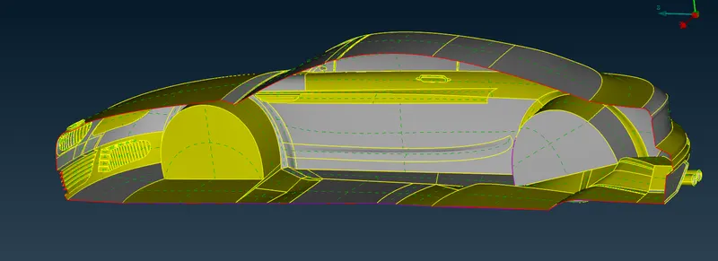
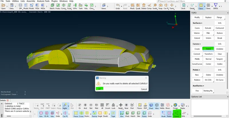
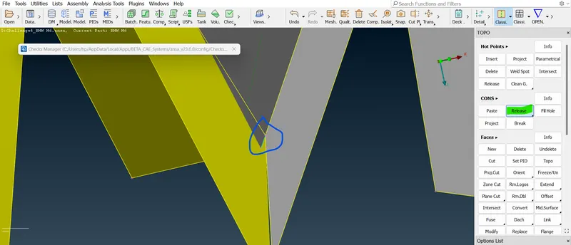
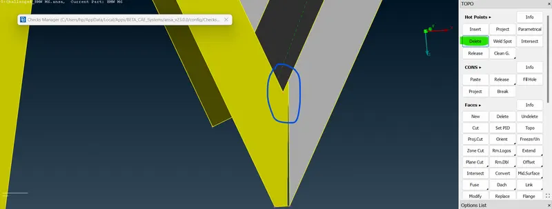
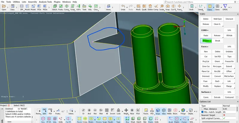
- In the back of the car inside there is same triple cons are presented there. so, we need to delete those triple cons and there should not be volume inside the car here. so, now the tin front wheel of the car there are many unwanted surfaces present. so, we need to rectify those all using "New, Extend, Past, Project, Delete tools" etc.
- =>
 =>
=>  =>
=> =>
=>  =>
=>  =>
=>  =>
=> =>
=> =>
=> =>
=> =>
=> =>
=>  .
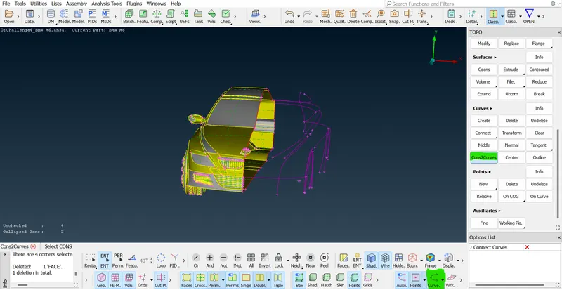
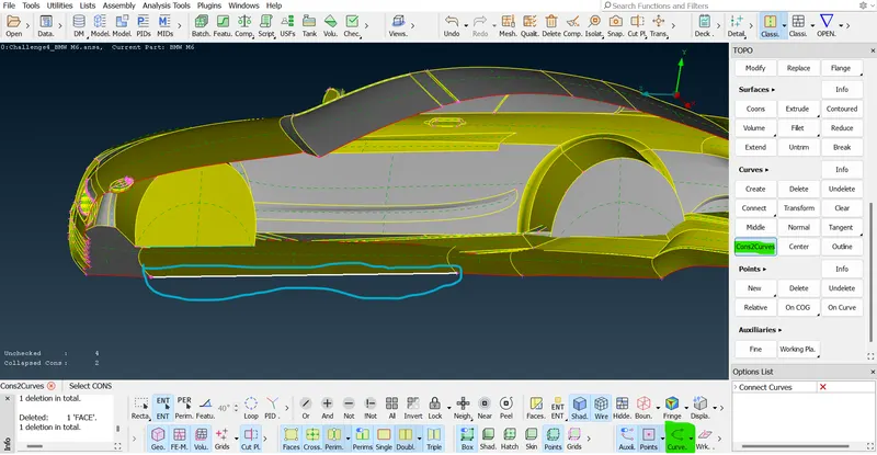
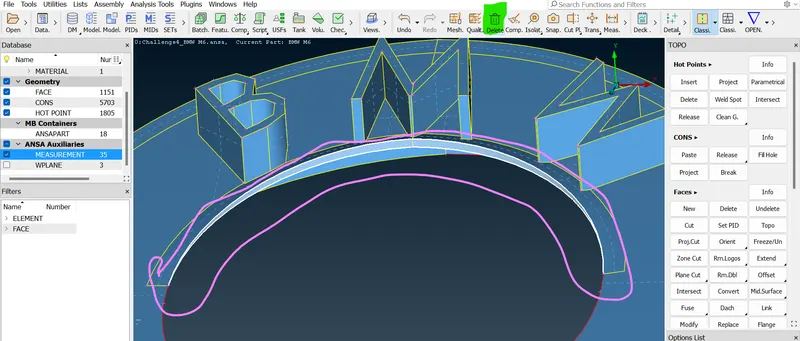
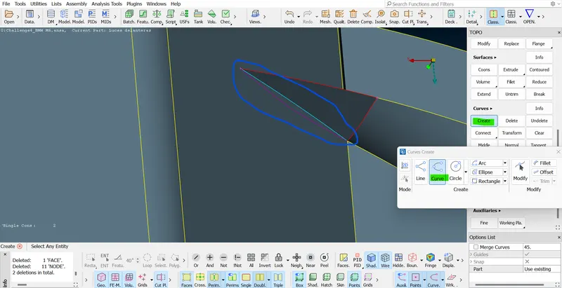
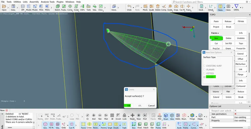
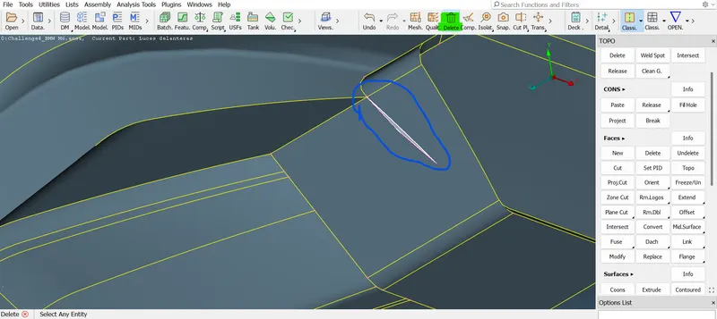
. - Now the "new option" is introduced that is namely "Curves 2 cons" in the curves section in topo mode ensure the Curvers logo is turned on then only it will work. this "Curves 2 cons" option is used to create a footprint of the cons in a purple color line. after turning on this option then we deleted some surfaces, we can also recreate the surface with the help of the footprints.
 =>
=>  =>
=>  =>
=>  =>
=>  =>
=>  =>
=> =>
=>  =>
=> =>
=>  =>
=>  =>
=>  .
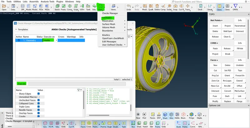
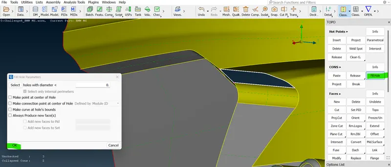
.- We almost finished the single cons double cons cleanup from our model and now we need to check the geomentry cleanup and check.
- So, we found there are no single cons and triple cons present. so, now we need to proceed with the different PIDs which means assigning PIDs with this particular model.
- So, first, we will see what parts this will have and the PIDs. we should create an assignment once we finished assigning PIDs. The next step will also give mesh length for different PIDs parts.
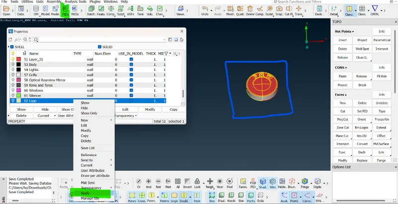
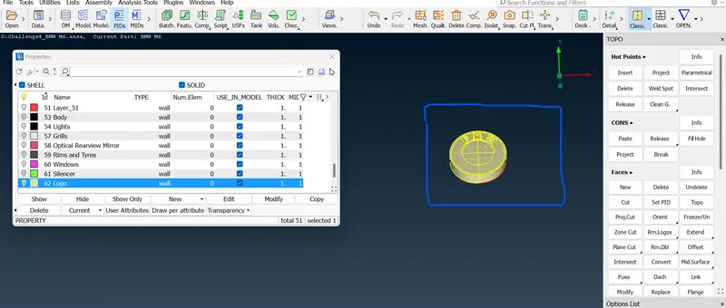
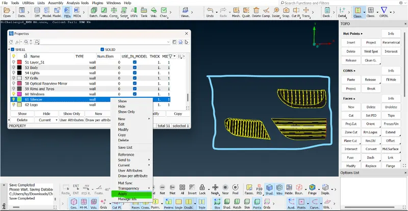
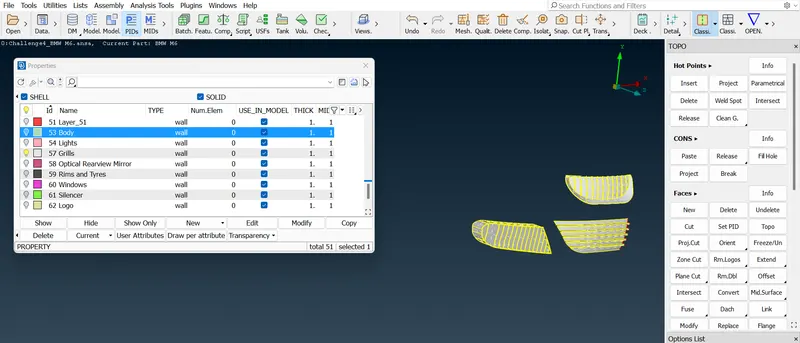
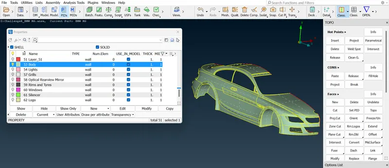
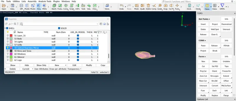
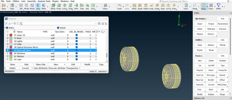
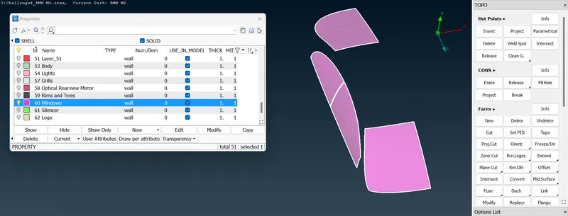
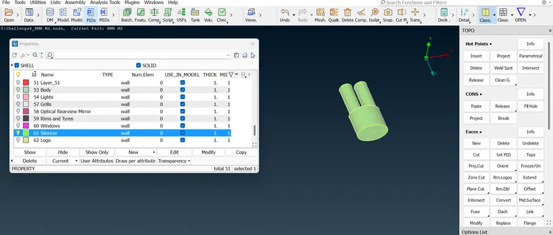
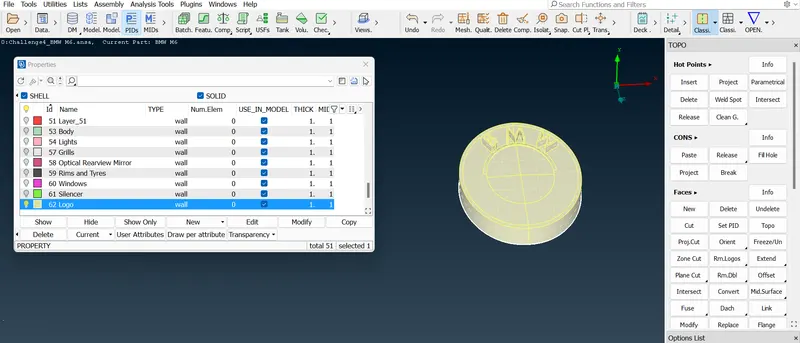
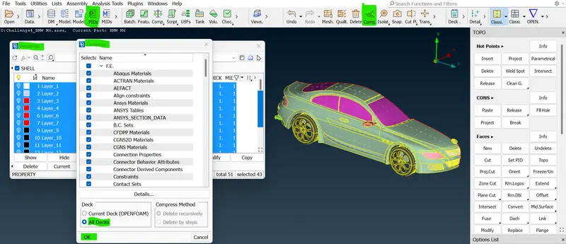
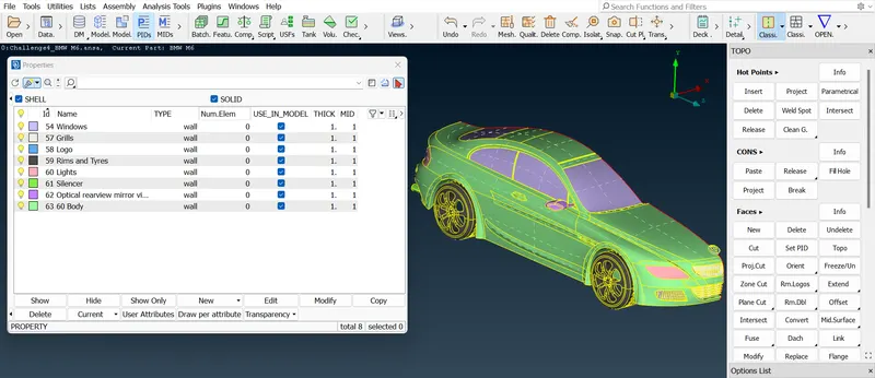
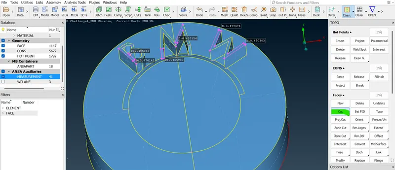
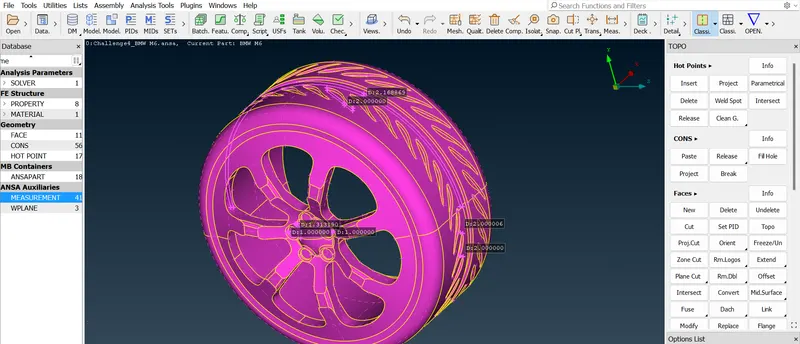
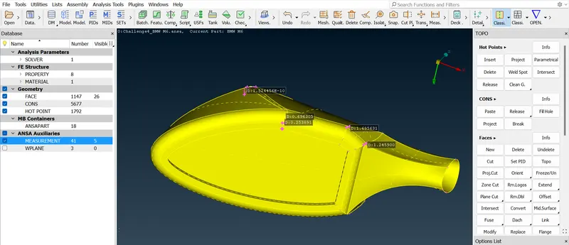
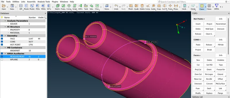
- We need to apply PIDs first to the BMW logo. so, click the "iNOT" option and select the logo and isolate in the PIDs section and click apply and click the All option to the entire model of the car. Similarly, repeat this process for all parts of the car.
 =>
=>  =>
=>  =>
=>  =>
=>  =>
=> =>
=> =>
=>  =>
=>  =>
=> =>
=> =>
=> =>
=> =>
=>  =>
=> =>
=>  =>
=>  .
.- So, we finished with assigning PIDs and now we will start with our model for giving different mesh lengths for our different PIDs. we are interested in CFD applications. so, we will be using tetra CFD element for TOPO our Volumatic mesh cover off.
- So, first, we need to deploy surface mesh for the different PIDs of the particular model and also we will have to check the quality criteria.
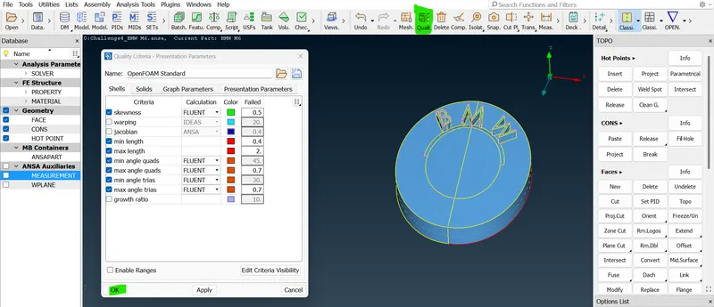
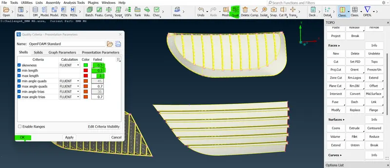
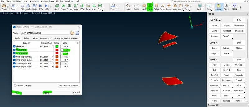
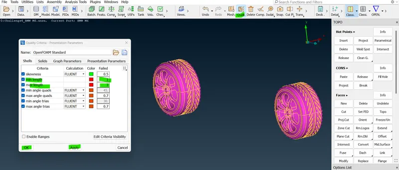
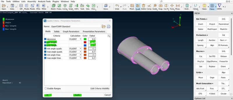
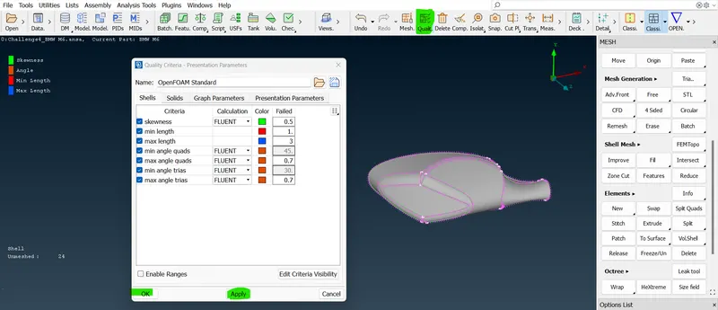
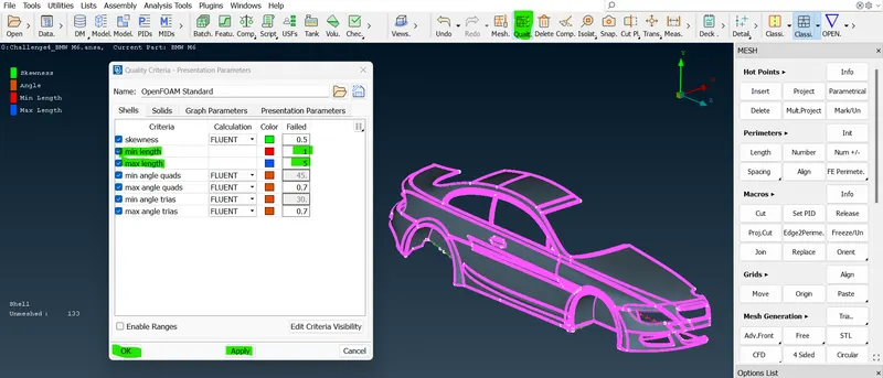
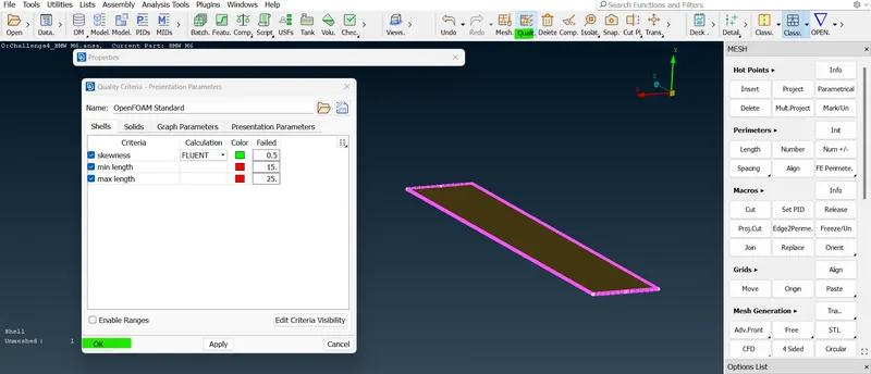
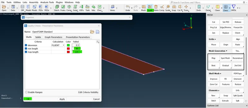
- Till now in the past week's section, we only gave a target length, and then we meshed it now we don't go inside this quality criteria there but we are supposed to do that. so, we need to use this ("OpenFoam") deck over here in the Dax. Once we received that deck after that click the quality criteria button on that. then we receive the list which we can add different quality criteria on it.
- Whenever we are going to do surface mesh we need to click on the mesh tag which will deal with shell property quality. so we can consider 2D elements and solids and we can consider 3D elements.
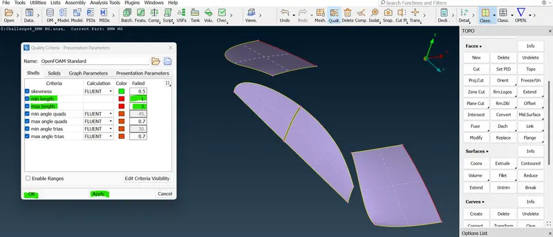
- So, the quality criteria is nothing but the quality of the particular element. so, in the quality criteria, we are already given some value examples:- skewness is 0.5. if the element cross below or above the value it will indicate that as in the Green color. and the remaining quality criteria are working in the same aspects.
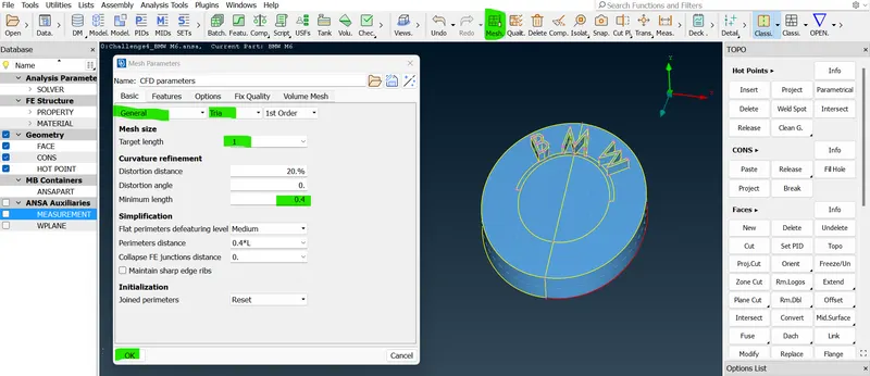
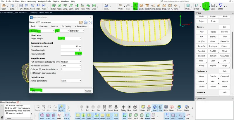
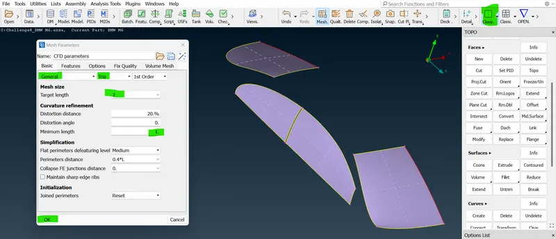
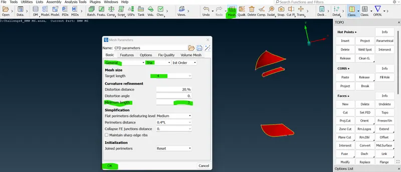
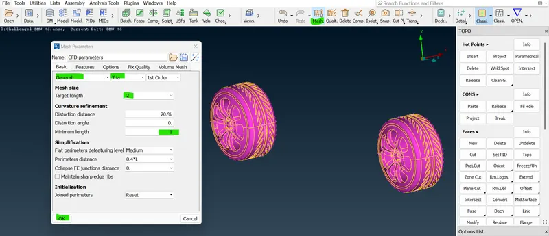
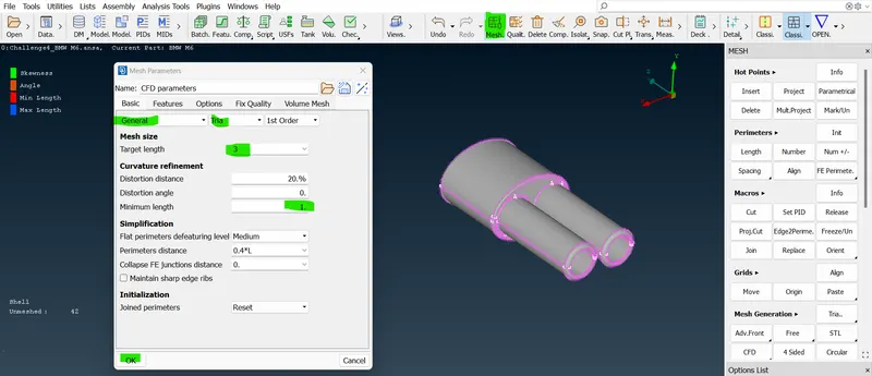
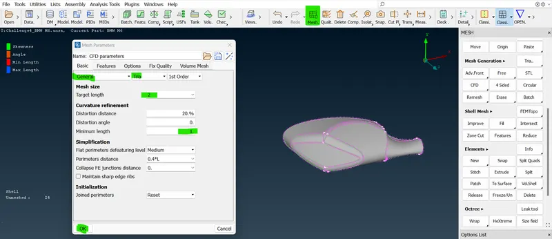
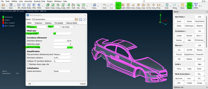
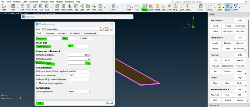
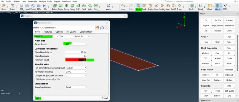
- So, we use only the tri-element and we don't use the quad-element for this part. and also we need to write the mesh parameters. and after giving the mesh parameter values we can also save that in the "Save mesh parameter to file" icon.
 =>
=> =>
=> =>
=> =>
=> =>
=> =>
=> =>
=> =>
=> .
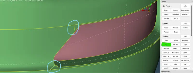
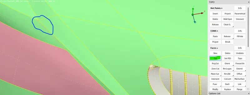
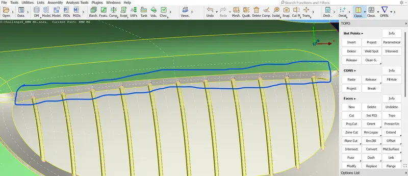
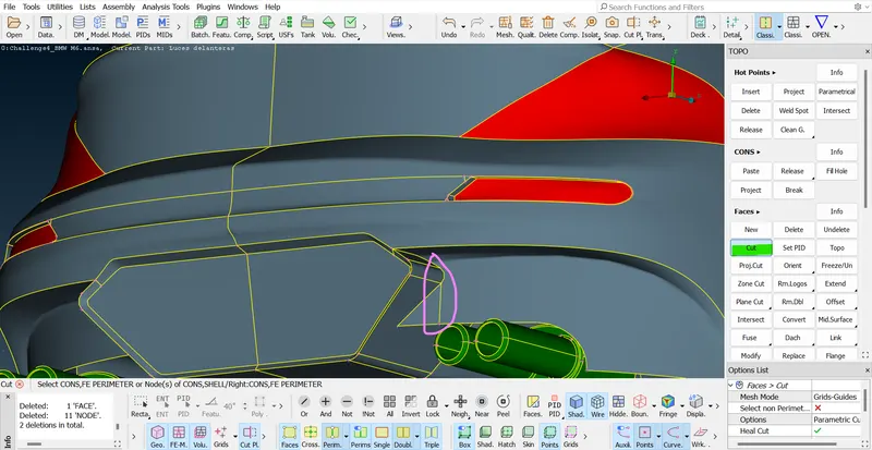
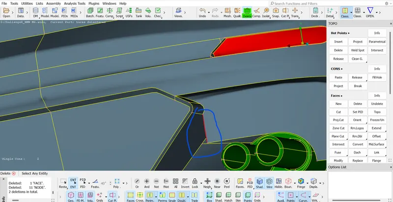
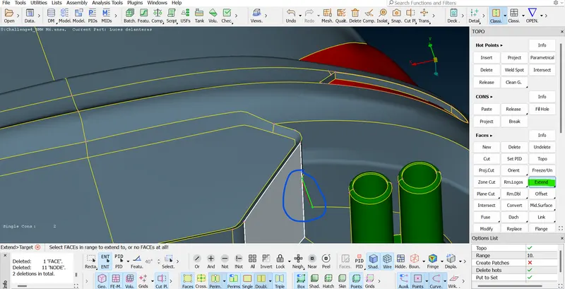
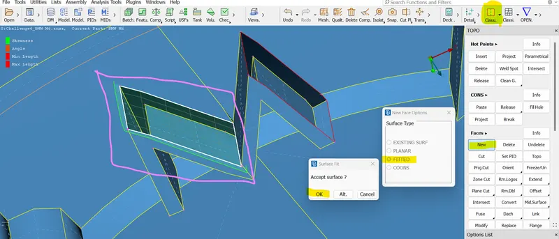
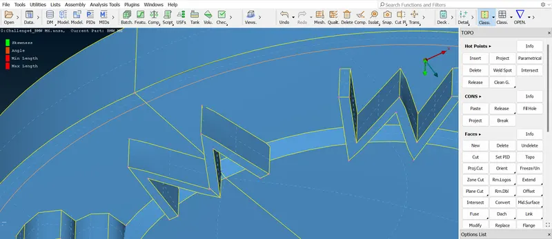
.- In this back side of the car the surface is present above of the silencer of the car so, we need to cut the in vertically and then extend that surface up to the neighbor surface distance and a project that surfaces in the neighbor surface and delete that surface. if we needae smooth surface without any intermediate cuts so, delete that created surface and create a NEW COONS surface using "NEW OPTION".
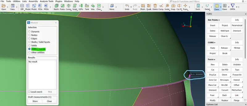
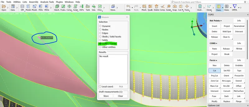
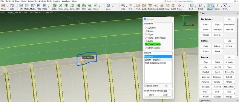
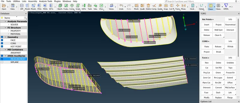
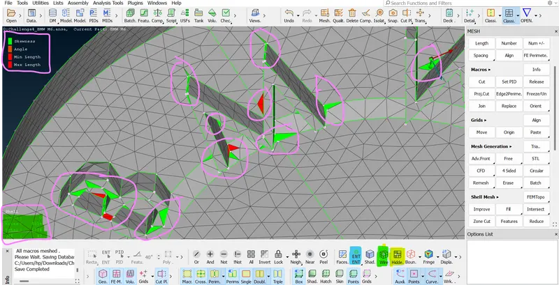
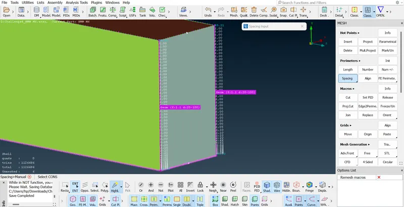
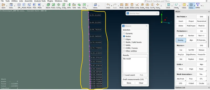
- So, before going to surface mesh we need to inspect the PIDs of all the parts. that means we need to check whether the part has the proper minimum target length or not. if not then we need to cut the cons and then measure the distance between one cons to another cons or node. hot points.
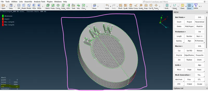
- So, doing this inspection we need to do topo clean-up work in part that is if needed after completing the inspection that means the distances are satisfied the minimum target length. we can procedure the meshing process. And there is a certain quality criteria we need to follow accordingly.
 =>
=> =>
=> =>
=> =>
=> =>
=> =>
=> =>
=> =>
=> =>
=>  =>
=> =>
=> =>
=> .
.- In previous times we tried solving all the hot points and cons distance by using the cut option for all over this car model. so, now we will try meshing.
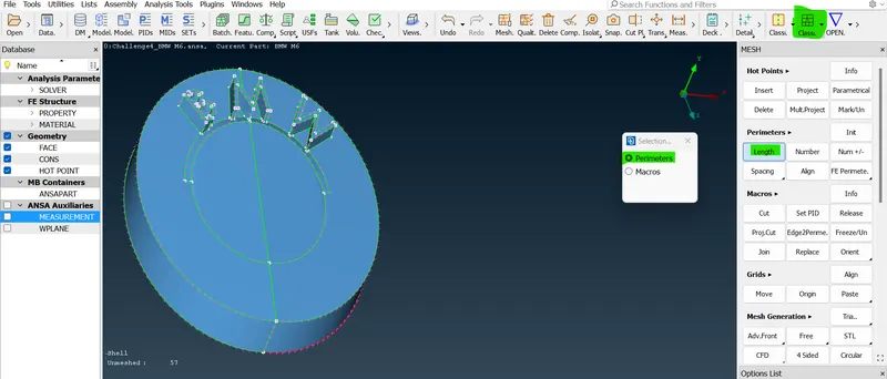
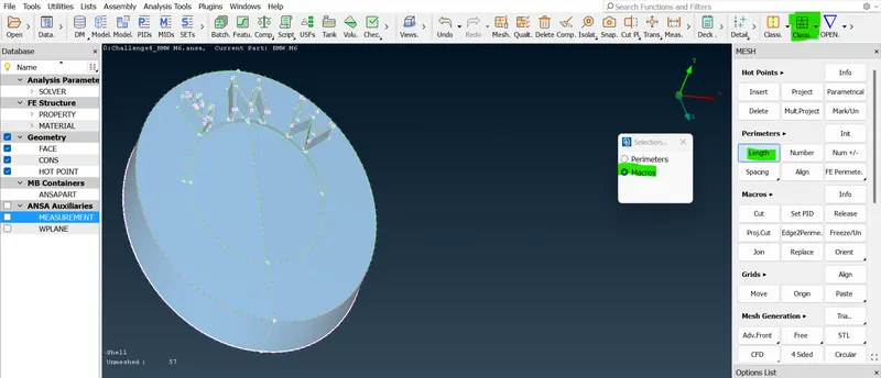
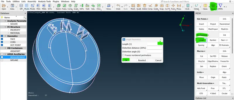
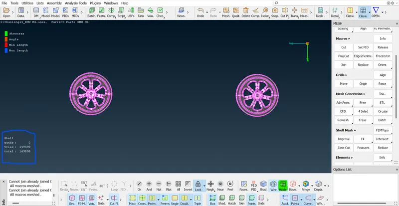
- So, let us start with the particular smallest surface, which is nothing but a logo. so, isolate the logo first. so, consider before meshing we should give the quality criteria like firstly mesh parameter and -> secondly the length in the mesh mode afterward.
 =>
=> =>
=> =>
=> =>
=> =>
=> =>
=> =>
=> =>
=> =>
=> =>
=>  =>
=> =>
=>  =>
=>  =>
=> =>
=> =>
=> =>
=> =>
=> =>
=> =>
=> =>
=>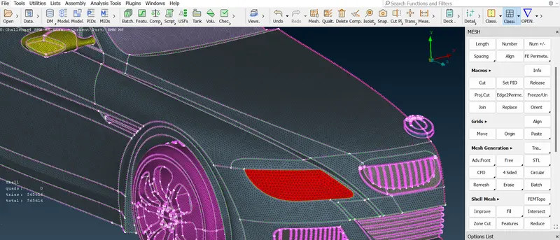 .
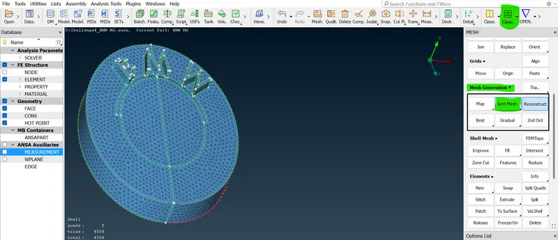
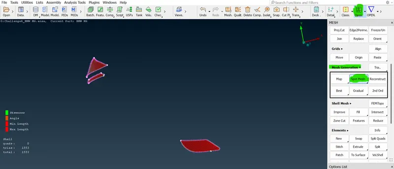
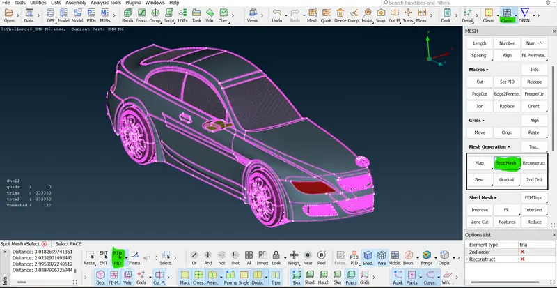
.- So, first give the quality criteria like skewness, minimum, maximum length, and mesh parameter. before doing this process now we can very well go with our mesh tag and here right click to select the entire model tag. and here right click to select the entire model and here right-click to select the entire model and middle-click given the long distance that is parameter and macro and clicks ok. now, go to mesh generation right click to select spot mesh. In that "select option" click visible option.
- So, now we can mesh the logo with tri-element and we to switch hidden mode here instead of the shadow option. so click the Ahidden feature at the bottom of the GUI and switch that model from PIDs mode to ENT mode.
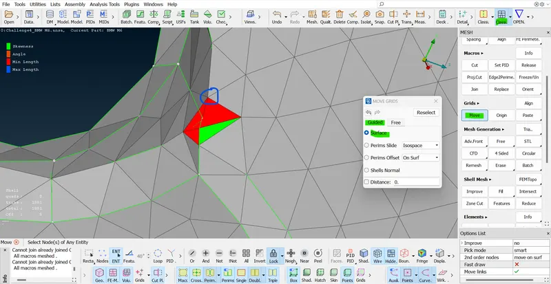 =>
=> =>
=>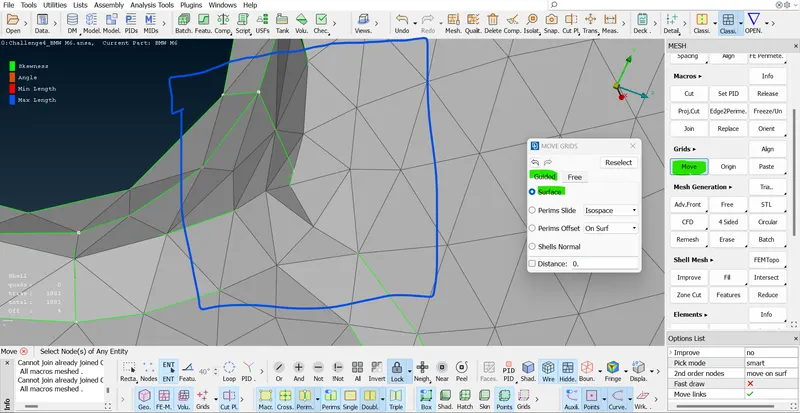 .
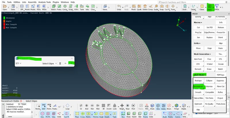
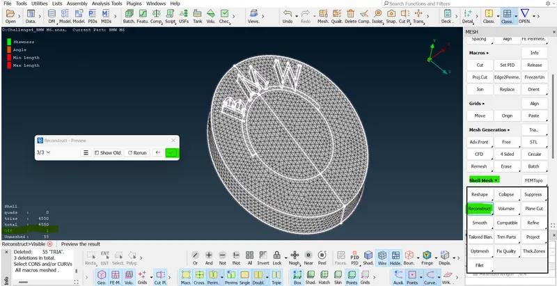
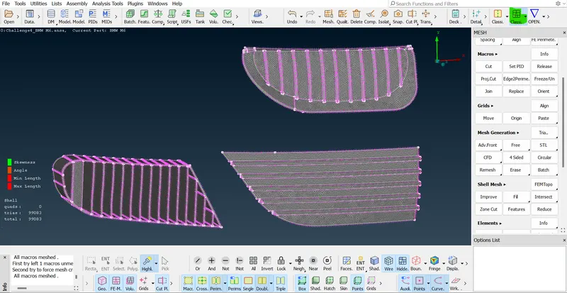
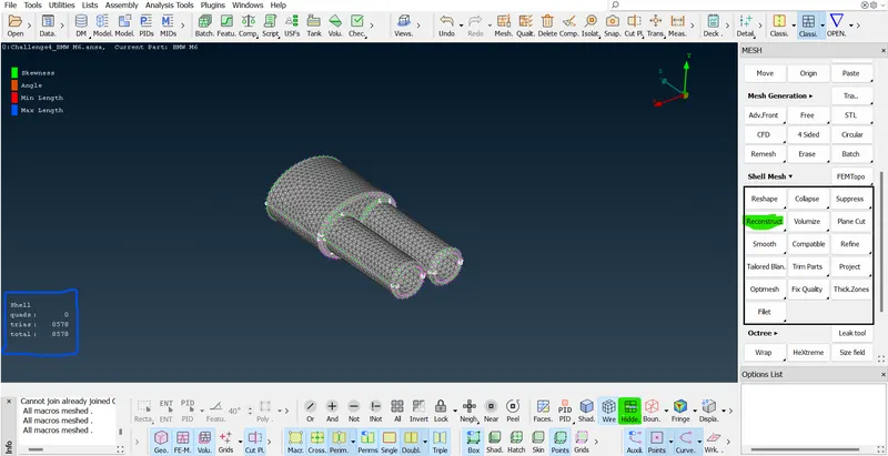
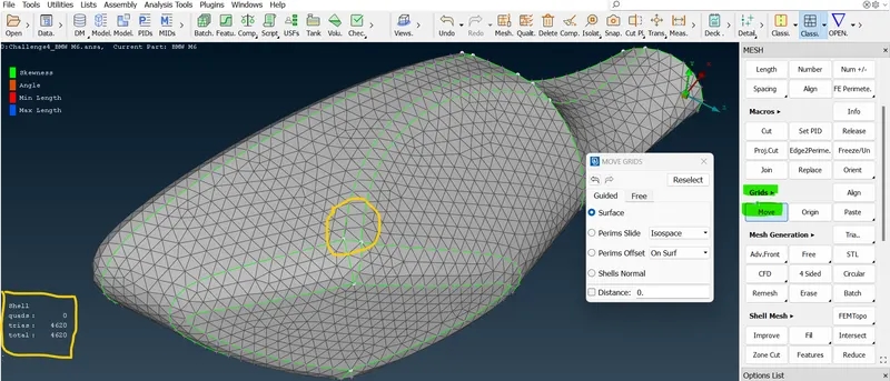
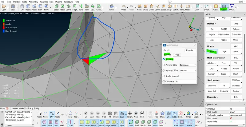
.- now we, very very well see the highlighted tri elements like skewness and angle and minimum and maximum length color. and we should consider the off-elements. our target is zero off-element or maximum low element.
- =>
 =>
=> =>
=>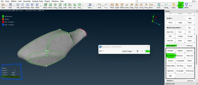 .
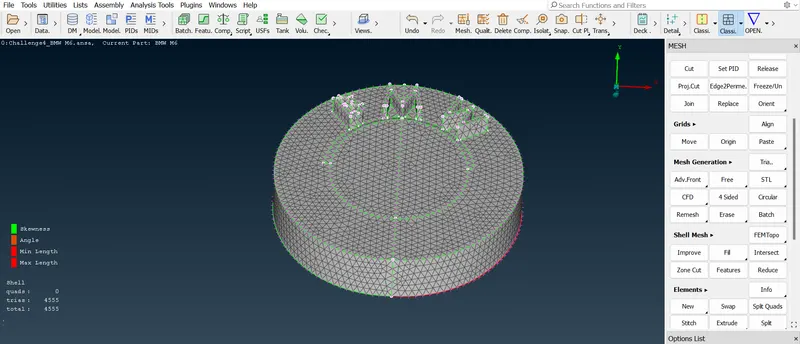
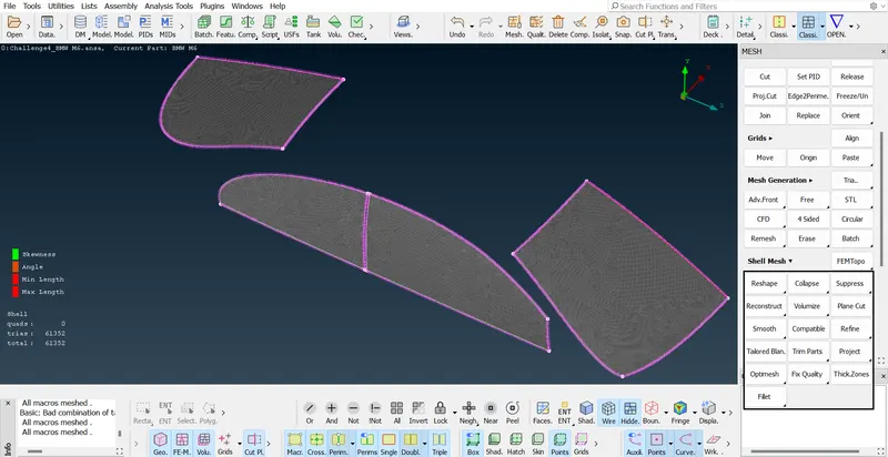
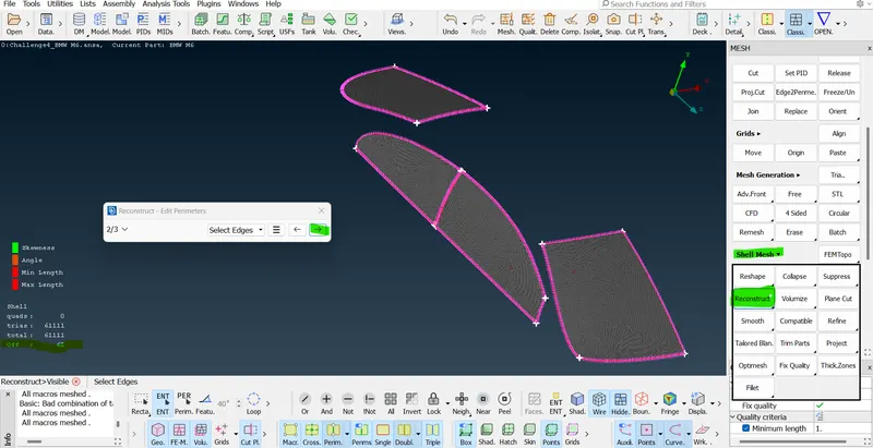
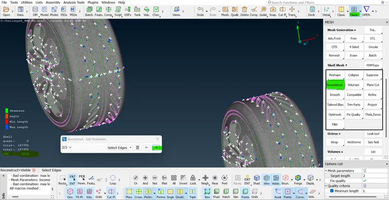
. - So, use the "Reconstruction option" in the shell mesh section right click to select the option. On that right click on Select visible and click Proceed arrow bottom. now the off element has been reduced maximumly. so, the logo part is completed so, now we can very well go with the next part the silencer. similarly, repeat the same procedure for this part.
- New tool features in mesh tag mode:- in that element this is a split option. split-> click "Edges" in the split option -> and now do select an element in the middle of the line -> the tri element is split into 2 or 3 parts.
- After splitting the elements now we need to smooth the element. so, in that "Shell mesh" -> smooth -> select smooth option -> select the required part of all elements only and then middle click.
- The smoothing option is used to try smoothing the mesh flow such that our off-element can be reduced automatically. so, it will try to do some node adjustments.
- In that grids section there is a move option. so, in this option, there is a guided and free option. if we have distance measurement then we can apply that in XYZ value and click ok. The smooth option is used to try smoothing the mesh flow such that our off-elements can be reduced automatically. so, it will try to do some node adjustments.
- In that grids section there is a move option. so, in this move option, there is a guided and free option. if we have distance measurement then we can apply that in XYZ value and click ok. Or else we can go with the guided surface option we can move the node manually to reduce minimum and maximum length error and skewness errors. so, we will keep on moving this until solve my element. the node adjustment is done here.
- And now suppose we don't want to move nodes. just use this "Origin" option in that grid section. so, select the origin option and drag select the part model, and then middle click. to get the original position of the model and the adjusted nodes get deleted.
- So, using this split option, smooth option, move option, and origin option are so used to solve reducing my off-elements. it is easy to reduce my off-elements. it is easy to reduce my off-elements because of our trip elements. instead of our quad or mix elements are difficult.
- In that mesh tag mode there is a macro in this section there is a "Cut option". it is used to cut the cons in the mesh node. so, that the off element can be reduced. but before doing this process we need to enable some options that are in the bottom right corner to enable the macro => join => Reconstruction. so, we are deleting the cons in many modes directly.
- Now meshing a body PID we have to change the meshing methods, so first isolate the body PID alone and in mesh mode select the length option to give perimeter length and before the middle some of the lines.
- So, it is nothing but we need to deselect the line which is in contact with other PIDs like window grill, side mirror light, and silencer region edges. the body line should not be in contact with any other PIDs. so, after selecting the perimeter line deselect a few of the lines that is contact with other PIDs.
 =>
=>  =>
=>  =>
=> =>
=>  =>
=>  =>
=>  =>
=> .
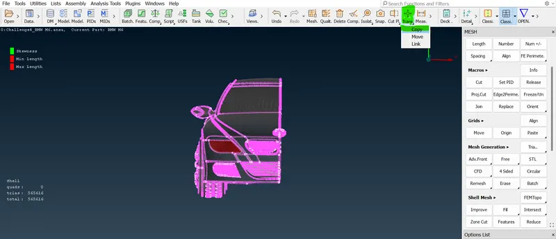
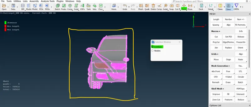
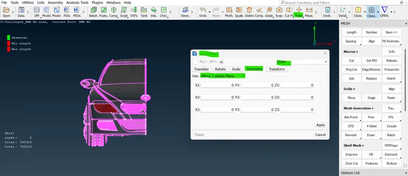
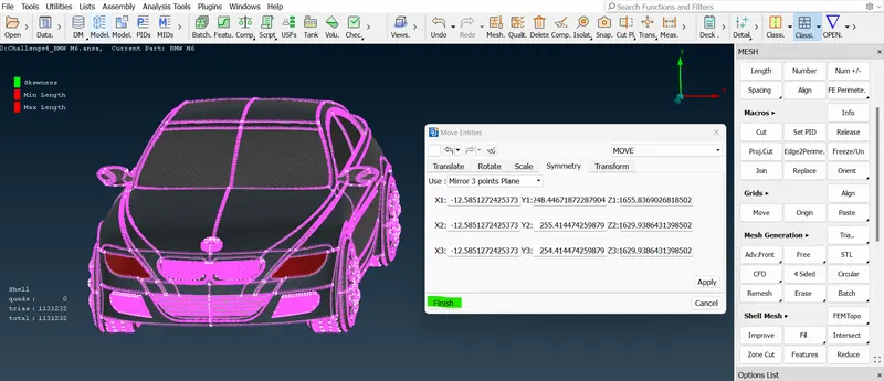
.- Now we completed the surface meshing and element using the reconstruction option. so, it is a good time now to symmetry our other half side part. so, on top of the GUI, there is a option called transform. so, in that option, there is copy and move and link option. the copy option is nothing but copying the half part or model or side. and paste that into another side. so, we get a complete full part the move option is moving the object from one to another place.
- So, on top of the GUI, there is an option called transform. so, in that option, there is copy and move and link option there is copy option is nothing but. copying the half part or model or side and pasting that into another side. so, we get a complete full part. the move option is moving the object from one to another place.
- Select the copy option in the transform option and new. select entities after selecting copy option. and then drag and select the model using the left mouse button for selecting the entities and surface together. and deselect the logo alone because there is no symmetry.
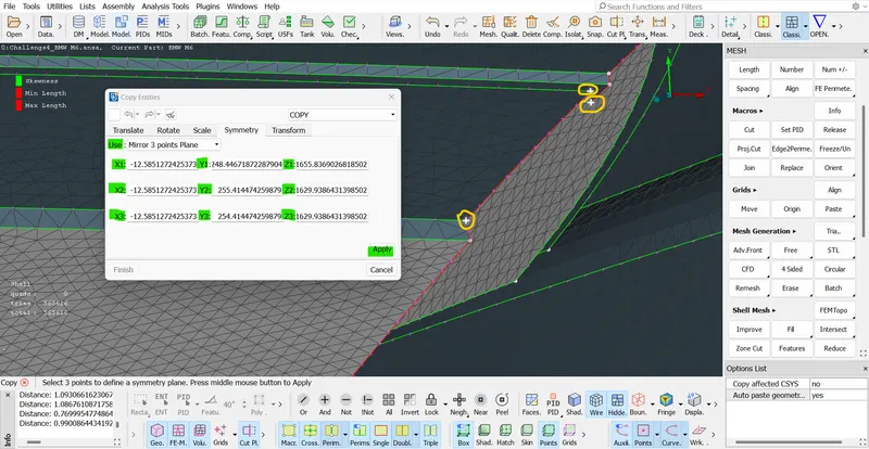
- So now every surface is selected for copying to the other side except the logo now does the middle click for confirmation. now another window is pop up in that window there is a distance needed for X1, X2, X3, and Y1, Y2, Y3, and Z1, Z2, and Z3 coming up.
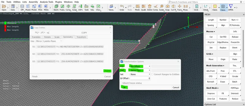
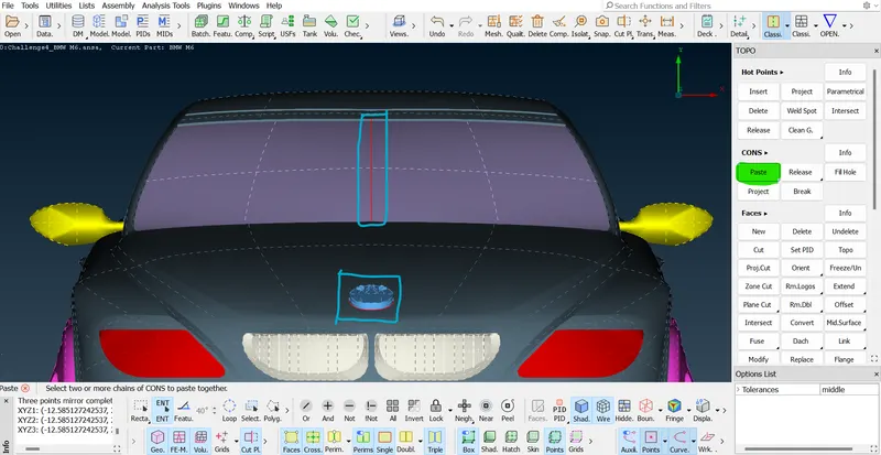
- So, we need to define three points so, such a way that the symmetry plane is defined after selected the three planes are defined after selected the three planes do a middle click. so, now we need to select the offset, we don't need to select the offset we don't need to change anything whenever it is we will keep it self. and click ok after the other half side model is created click finish.
- "Transform" => select entities option => drag to select the car model using shit & left mouse button => now fill the three X1 Y1 Z1 and X2 Y2 Z2 and X3 Y3 Z3 value in the symmetry option and also choose mirror 3 point plane. and now select any three hot points and then do the middle click => now "Offset" will pop up => in that offset selection just select the part as a "Same part" click ok => the part created click finish.
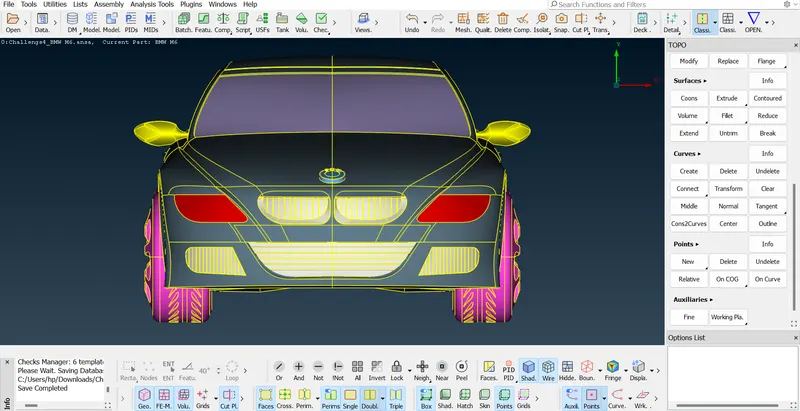
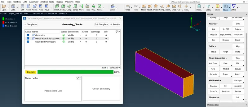
- Now check the model like single cons and double cons are presented correctly or not. if not then we need to check and do some TOPO cleanup and geometrical check. so, after solving this single cons. our model is ready to keep inside of the wind tunnel.
 =>
=> =>
=> =>
=> =>
=> =>
=> =>
=> =>
=> =>
=>  =>
=> =>
=> =>
=> =>
=> .
.- Important note:- once completed meshing part is complete and the symmetry part also once completed these two processes. after setting the quality criteria as a low minimum length and highest length in the entire model then only we can reduce the off-elements.
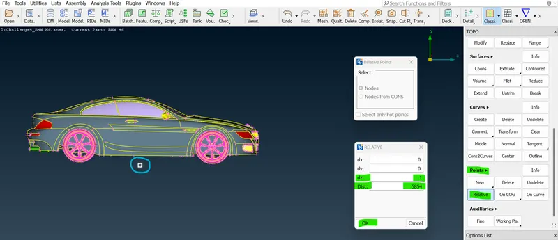
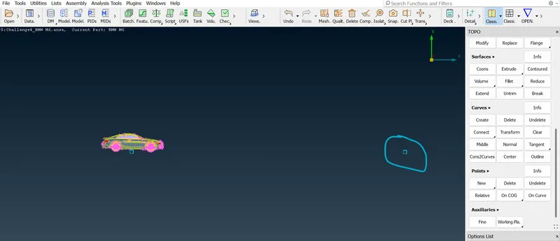
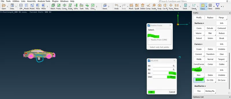
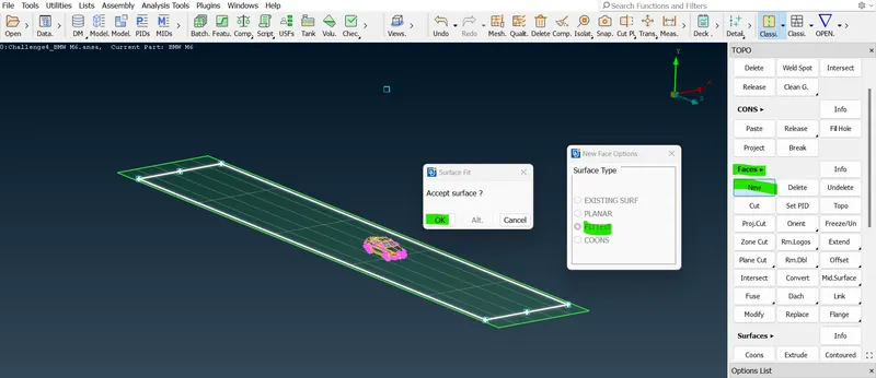
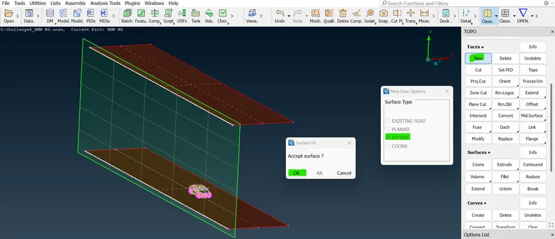
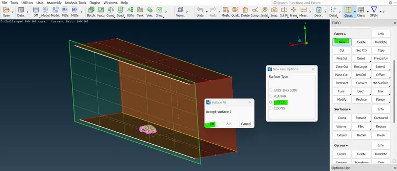
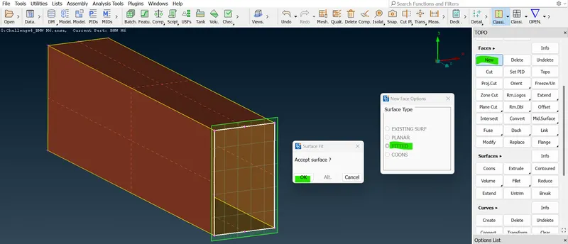
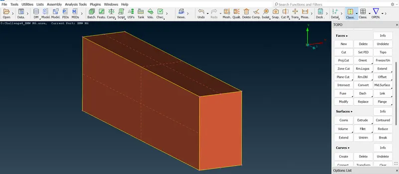
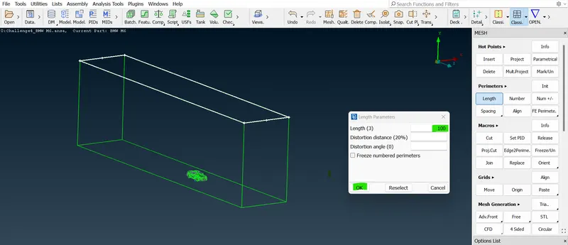
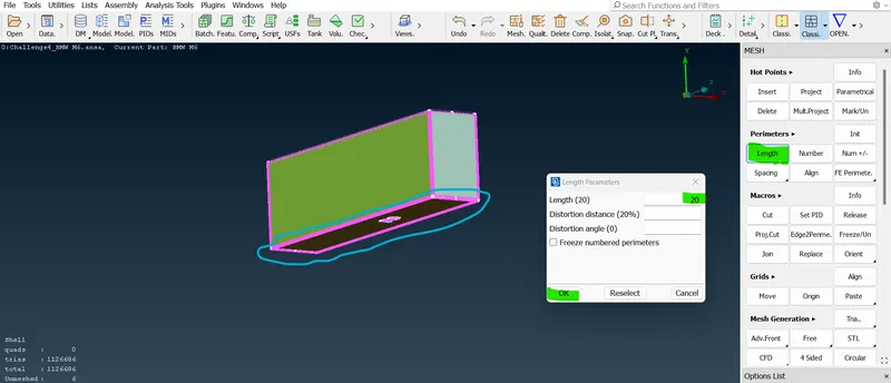
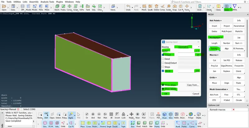
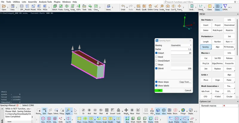
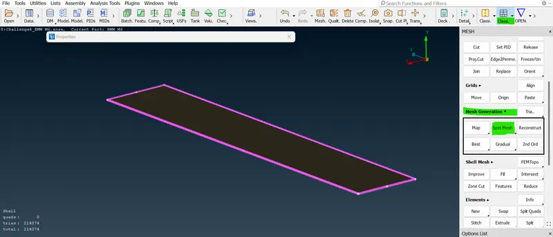
- Now the final step is we need to create a wind tunnel and volumetric mesh. so, for creating a tunnel there is a certain standard for wind tunnel. the Front face of the wind tunnel would be 4X the distance which is nothing but "650 + ( 4*1300 ) = 5850mm." from any point of our front car model.
- The rear face of the wind tunnel would be 6X the distance which is nothing but "650 + ( 6*1300 ) = 8450mm." from our rear side point.
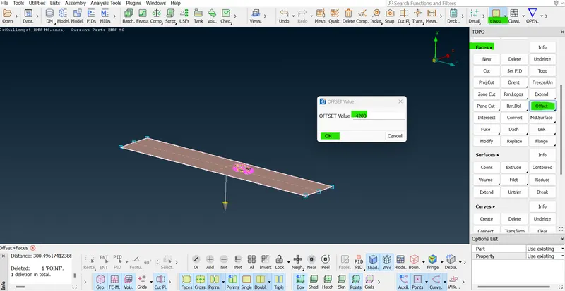
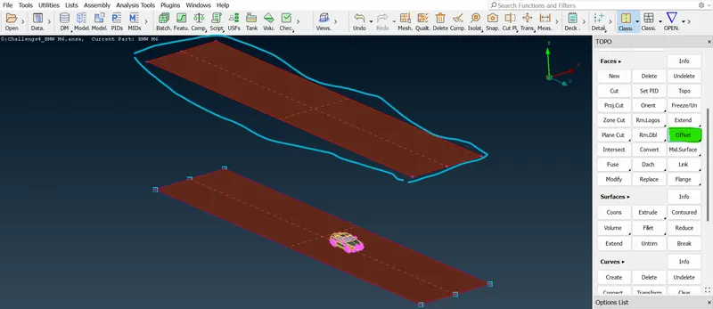
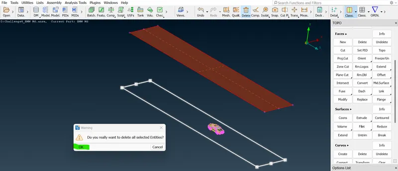
- The top face of the wind tunnel would be 3X the distance which is nothing but "300 + ( 3*1300 ) = 4200mm." from any bottom side point.
- And both sides of the wind tunnel would be the actual distance alone which is nothing but "1300mm" from the mid-center of the car point.
 =>
=> =>
=> =>
=> =>
=> =>
=> =>
=> =>
=> =>
=> =>
=> =>
=> =>
=> =>
=> =>
=> =>
=> =>
=> =>
=> =>
=> =>
=> =>
=> .
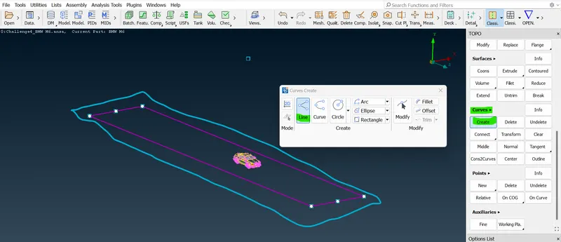
.- The bottom face of the wind tunnel would be near the wheels.
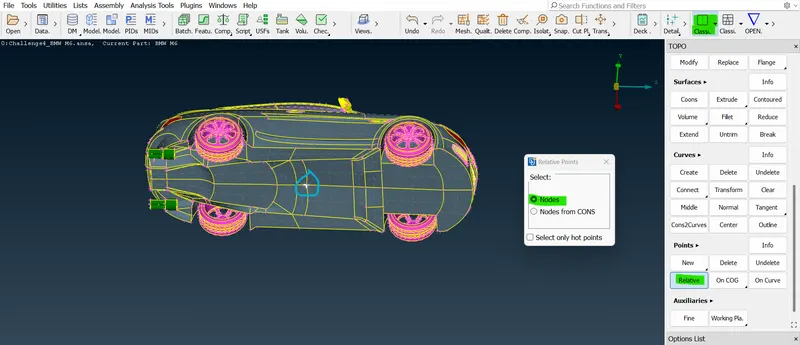
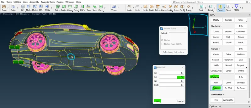
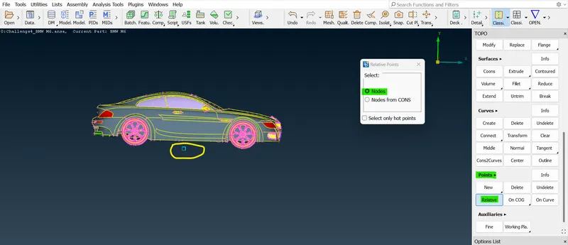
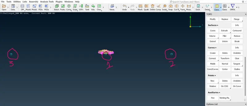
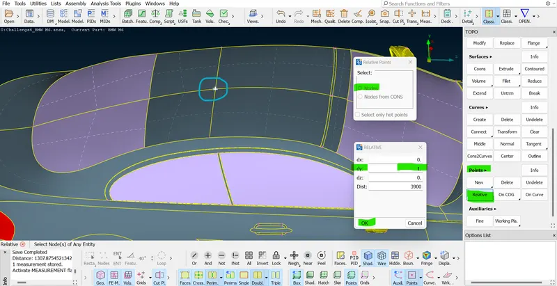
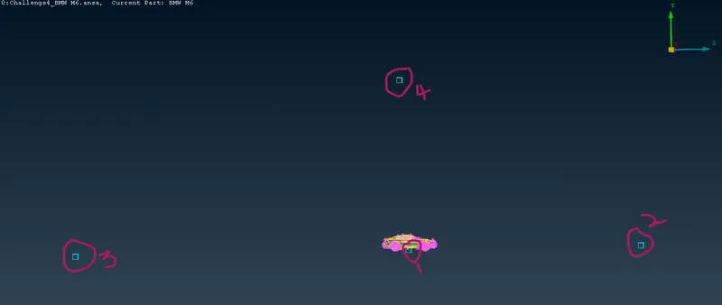
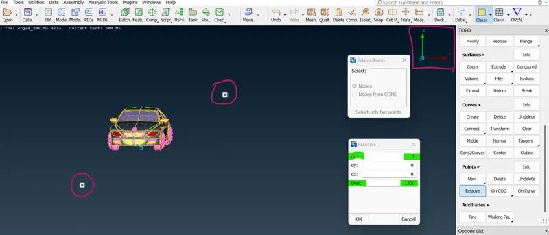
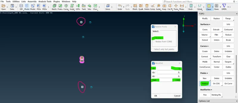
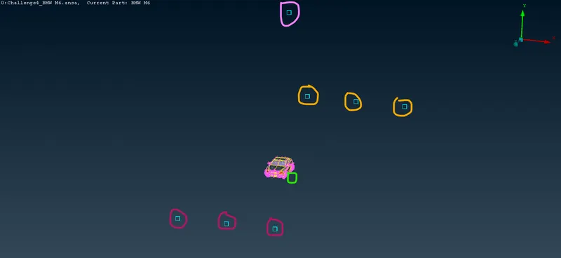
- So, to create a surface we should create so, many points first. and then we can create a surface indirectly. so, select a relative for crating points for the surface.
- Select "Relative" in the points section of topo mode. select the bottom middle of the hot point in the car and then middle click and then enter the value in either dx, dy, dz any one of these with the correct symbol.
 =>
=> =>
=> =>
=> =>
=> =>
=> .
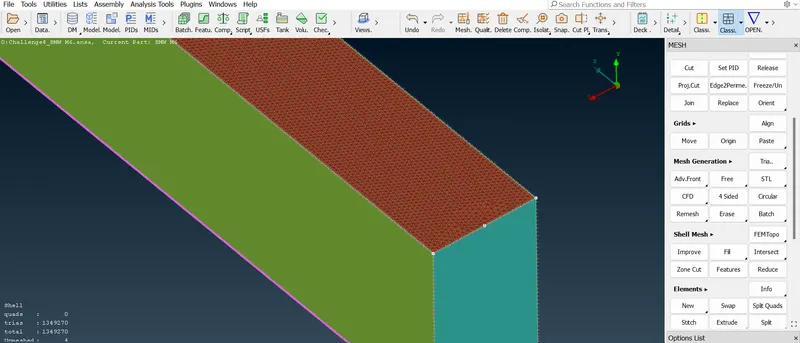
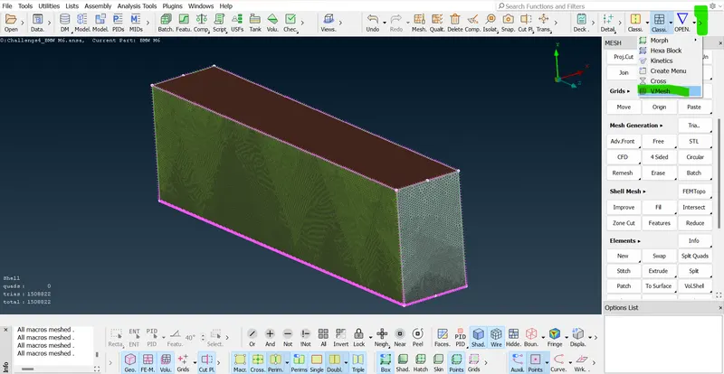
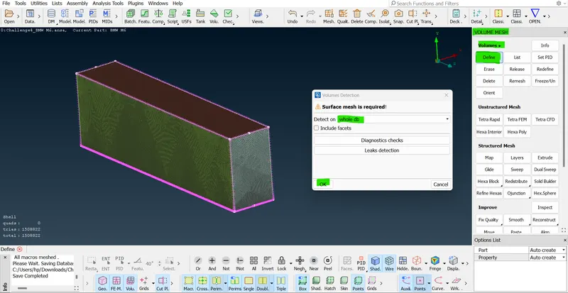
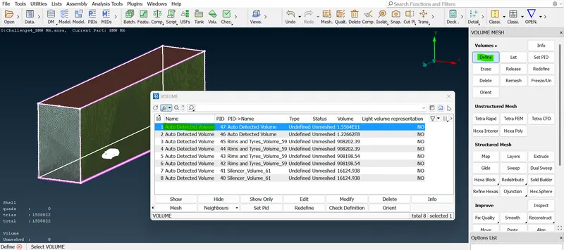
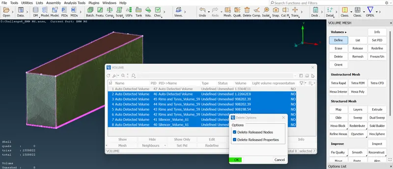
.- Now we successfully assigned PIDs and the surface meshing process has been completed. so, we can very well go for the volumetric section. for, this process we need to to go the first volumetric section and then click the" Define option " and "Select the whole database option" in that define option and, click ok. now the ANSA software has detected a total of 8 volumes.
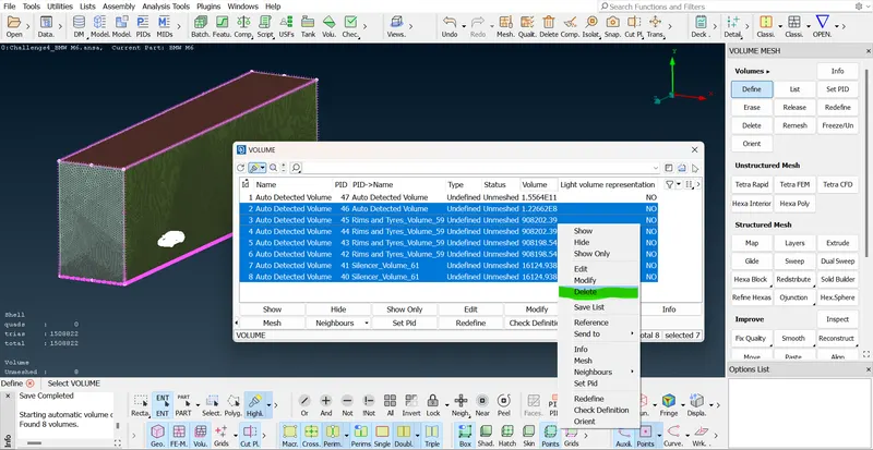
- So, our task is to keep only one volume. so, keep 1st volume alone and then delete the remaining 7 volumes. so now select the entire car volume and then right-click to mesh and the mesh should be in Tetra CFD.
LEARNING OUTCOME:-
So this week I have learned how to clear the advanced topological clean-up like this car or similar models and the surface mesh and the creating a Wind Tunnel with the distance calculation.
RESULT:-
Hence, All the geometric errors and assigning the PIDs and the surface meshing with the target length and the quality criteria, and the Symmetry of the other sides are successfully done with the checks manager.
CONCLUSION:-
Finally the Topology was been cleared with all the double cons which is needed for the volume to create and the different mesh sizes for all the PIDs were assigned and surface meshed by refining the mesh as well as errors.