Week 5 Challenge
1)
ANS:-
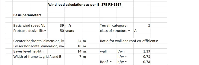
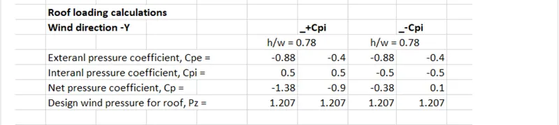
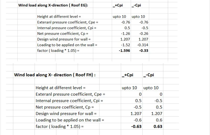
AIM:- To generate manual wind loading in the design report based IS code as per the following input.
TOOLS REQUIRED:
- IS code book.
- Calculator.
- Ms Excel.
PROCEDURE:-
- First we have to open Microsoft Excel and enter the require values for calculation.
- Now we should check required standard values from IS code book.
- Now w should measure the dimensions of the project in terms of length,breadth and height.
- Now assume basic wind speed as 39m/s (Given).
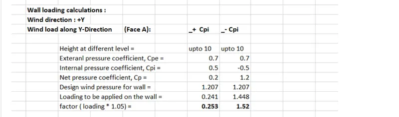
- Now calculate the wind direction in both the directions i.e.X(+Cpi)&Y(-Cpi) directions.
- Now we should calculate.
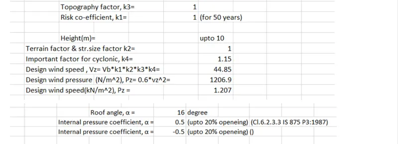
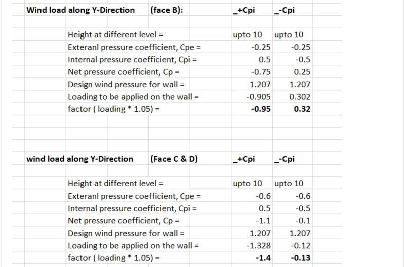
- External pressure co-efficient.
- Internal pressure co-efficient.
- Net pressure Co-efficient.
- Design wind pressure for wall.
- Loading to be applied on the wall.
RESULT:-
Therefore by following above procedure we can obtain all the required values & then we can start the manual calculation procedure successfully.
2)
ANS:-
To create the required loadings on the model as per above calculations.
PROCEDURE:-
- Firstly we should open the previous file in order to apply the wind loads to the project .
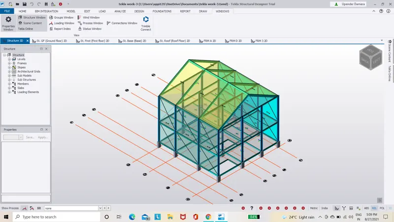
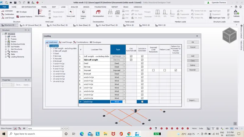
- Now select load cases option from tool bar and then add required 8 wind loads.
- The required 8 wind loads are as follows.
- wind+y+cpi.
- wind+y-cpi.
- wind-y+cpi.
- wind-y-cpi.
- wind+x+cpi.
- wind+x-cpi.
- wind-x+cpi.
- wind-x-cpi. as shown below.
- After adding the required loads,now apply those loads to the structure.
- Now set the directions for face C & D to global X.
- Now set the directions for face A & B global Y.
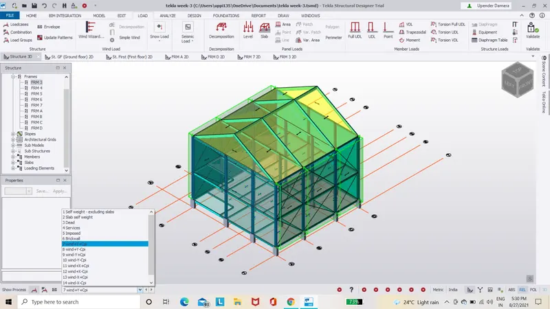
- NOw set the directions for roof component to global Z.
- Then apply +cpi and -cpi values to all other sides.
- Selecting Frame D and selecting the wind+y+cpi applying the load of 0.24 on face A,similarly selecting Frame D and selecting the wind+y-cpi applying the load of 1.44 on face A.
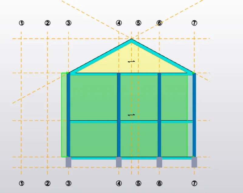
- Selecting Frame A and selecting the wind+Y+cpi applying the load of -0.9 on Face B.
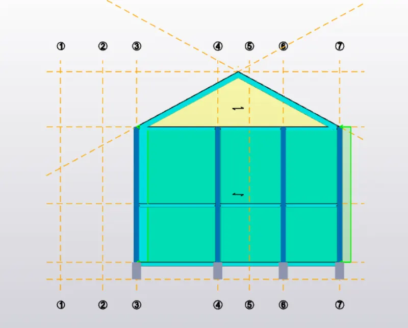
- and similarly Selecting Frame A and selecting the wind+y-cpi applying the load of .3 on face B.
- Selecting the frame 2 and frame 8 and selecting the wind+y+cpi applying the load of 1.32 on face C and Face D.
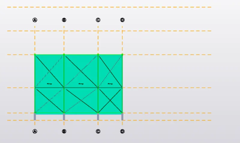
- Selecting frame 2 and Frame 8 and selecting the wind+y-cpi applying the load of -0.12 on face C and Face D.
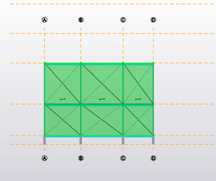
- Applying Roof loads of -1.44 and O on both the roof tops on both sides.
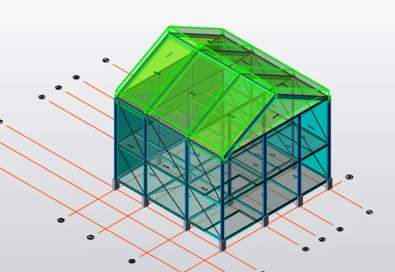
RESULT:-
Therefore the wind loads are successfully applied on the model.
3)
ANS:-
AIM:- To create a separate model and generate wind loading using wind wizard.
PROCEDURE:-
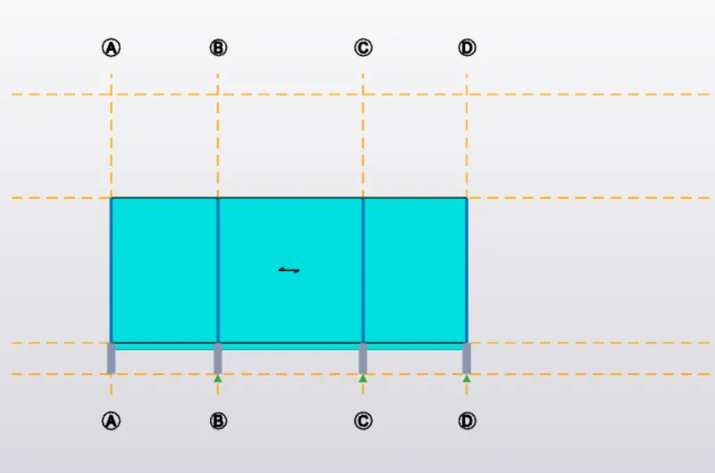
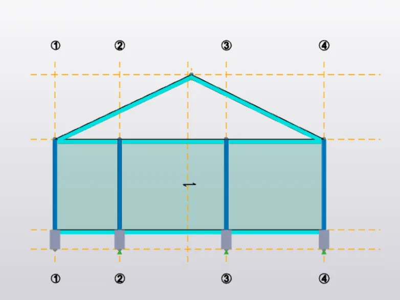
- Firstly on the workspace create a model of your choice.
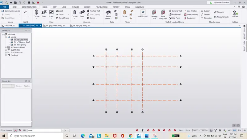
- That is to create the grid and assign the columns,beams as per the requirement for the building.
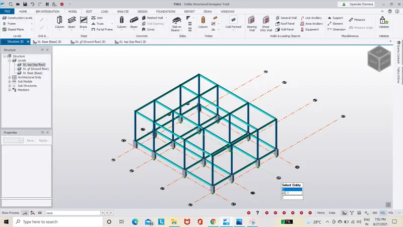
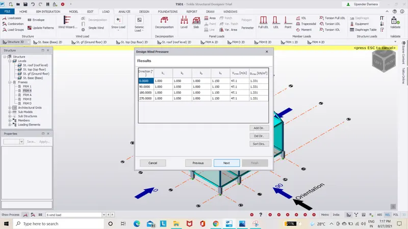
- Now select the wind wizard option and you will be directed to a dialouge box on the workspace.
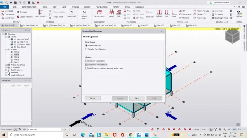
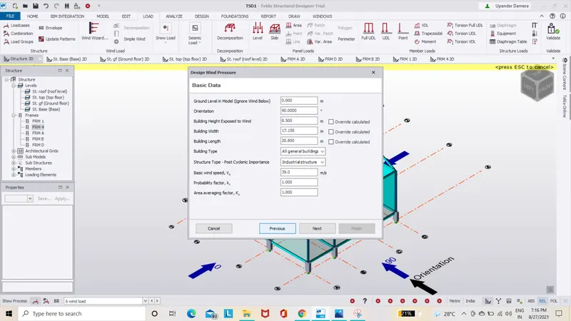
- Now select next and finish because all the values of the structure are already taken by the software itself and there is no values that you have to change.
- Click ok and the work is done.
RESULT:-
Hence by following the above procedure we will be able to crate a seperate model and generate wind loading using wind wizard.