Week 5 Challenge
1. Basic Design Data: ( For Pier Foundation) using IRC:6,112,78
| Basic Designdata: - | |||||||
| Span and Cross Section Data | |||||||
| C/C of expansion gap@ Left Span | = | 13.30 | m | (Sq.) | |||
| C/C of Bearing@ Left Span | = | 12.30 | m | (Sq.) | |||
| Distance of Bearing to expansion gap @ Left Span | = | 0.50 | m | (Sq.) | |||
| Girder Overhang beyond bearing@ Left Span | = | 0.35 | m | ||||
| C/C of expansion gap@ right Span | = | 13.30 | m | (Sq.) | |||
| C/C of Bearing@ right Span | = | 12.30 | m | (Sq.) | |||
| Distance of Bearing to expansion gap | = | 0.50 | m | (Sq.) | |||
| Girder Overhang beyond bearing@ right Span | = | 0.35 | m | ||||
| Carriage way width | = | 11.00 | m | ||||
| Total Width | = | 12.00 | m | ||||
| No of Longitudinal Girders | = | 4.00 | Nos | ||||
| C/C spacing of the Longitudinal girder | = | 3.00 | m | ||||
| Footpath width (left Side) or Parapet | = | 0.50 | m | ||||
| Footpath width (right Side) | = | 1.50 | m | ||||
| Crash Barrier (Left Side) | = | 0.50 | m | ||||
| Crash barrier (Right Side) | = | 0.50 | m | ||||
| CG of Crash Barrier | = | 0.373 | m | ||||
| Handrail width (Left Side) | = | - | m | ||||
| Handrail (right Side) | = | - | m | ||||
| Wearing Coat thickness | = | 0.065 | m | ||||
| Super-Structure Details: | |||||||
| Depth of Superstructure @Left Span | = | 1.320 | m | ||||
| Depth of Superstructure @Right Span | = | 1.320 | m | ||||
| CG of Super-structure from @Left Span | = | 0.880 | m | ||||
| CG of Super-structure from @Right Span | = | 0.880 | m | ||||
| Height of Crash Barrier | = | 0.900 | m | ||||
| Bearing Thickness (Max) | = | 0.065 | m | ||||
| Height of Pedestal | = | 0.250 | m | Min | |||
| Expansion Joint | = | 0.040 | m | ||||
| Skew Angle | = | - | o | 00.00 radians | |||
| Super_Elevation/Camber | = | 2.50% | m | ||||
| Type of Super-Structure | = | RCC Girder & Deck | |||||
| Typical Levels:- | |||||||
| Formation Level FRL | FRL | = | 230.115 | m | |||
| Bearing Level | BRL | = | 228.458 | m | |||
| Pier Cap Top Level | CTL | = | 228.143 | m | |||
| Footing top level | FTL | = | 217.262 | m | |||
| Footing bottom level | FBL | = | 216.262 | m | |||
| Lowest Bed Level | LBL | = | 224.178 | m | |||
| Max. Scour Level | MSL | = | 218.262 | m | |||
| Height Flood Level | HFL | = | 227.105 | m | |||
| Lowest Water Level | LWL | = | 224.178 | m | |||
| Founding Level (Actual) | FL | = | 216.262 | m | |||
| Founding Level (Actual) | FL | = | 216.260 | m | |||
| Water Current Data | |||||||
| Max. Mean Velocity | = | 0.98 | m/s | ||||
| Constant K for Pier in transverse Direction | = | 0.66 | |||||
| Constant K for Pier in Longitudinal Direction | = | 1.50 | Cl.210.2,IRC:6-2014 | ||||
| % of Uplift Considered | = | 100% | |||||
| Material Data:- | |||||||
| For Pier Cap, Pier & Footing | |||||||
| Grade of Concrete | fck | = | M 35 | ||||
| Design strength of Concrete | fcd | = | 15.63 | MPa | (Cl.6.4.2.8,IRC:112-2020,Page-38) | ||
| Modulus of elasticity of steel | Es | = | 2.00E+05 | MPa | |||
| Modulus of elasticity of Concrete | Es | = | 3.20E+04 | MPa | |||
| Mean Axial Tensile strength of concrete | fctm | = | 2.80 | MPa | |||
| Grade of steel | fyk | = | Fe 500 | ||||
| Design strength of Steel | fyd | = | 434.78 | ||||
| Density of concrete | = | 2.50 | t/m3 | Cl.203(6),IRC:6-2010 | |||
| Density of wearing coat | = | 2.20 | t/m3 | ||||
| Co-efficient of thermal expansion of concrete | = | 1.20E-05 | /oC | (Cl.215.4,IRC:6-2014) | |||
| Shrinkage Strain for Concrete | = | 2.00E-04 | (Cl.217.3,IRC:6-2014) | ||||
| Soil Parameters:- | |||||||
| Angle of shear resistance “ | = | 30 | o | ||||
| Density of dry backfill “ | = | 2.00 | t/m3 | ||||
| Density of submerged backfill, “ | = | 1.00 | t/m3 | ||||
| HFL Case | |||||||
| Net Bearing Capacity at founding Level | = | 25.00 | t/m2 | ||||
| Gross bearing capacity | = | 29.00 | t/m2 | ||||
| Net Safe Bearing SBS Seismic Case | = | 31.25 | t/m2 | ||||
| Gross Bearing SBS Seismic Case | = | 33.25 | t/m2 | ||||
| LWL Case | |||||||
| Net Bearing Capacity at founding Level | = | 25.00 | t/m2 | ||||
| Gross bearing capacity | = | 40.84 | t/m2 | ||||
| Net Safe Bearing SBS Seismic Case | = | 31.25 | t/m2 | ||||
| Gross Bearing SBS Seismic Case | = | 33.25 | t/m2 | ||||
| Type of soil | = | Medium Soil | |||||
| Co-efficient of friction between the. | = | 0.50 | |||||
| Load Data:- | |||||||
| Deal Load@ Left Span | |||||||
| Total Weight of Super-Structure | = | 199.00 | t | From staad | |||
| Deal Load@ Right Span | |||||||
| Total Weight of Super-Structure | = | 199.00 | t | From staad | |||
| SILD ( Excluding wearing Coat) | |||||||
| Self- weight of Crash Barrier | = | 1.0 | t/m | ||||
| Self- weight of Railing/ Parapet(One Side) | = | - | t/m | ||||
| Transverse eccentricity of crash barrier ( | = | - | m | ||||
| Transverse eccentricity of Railing or Para | = | - | m | ||||
| Transverse eccentricity of Railing or Para | = | - | m | ||||
| Transverse eccentricity of footpath/servic | = | - | m | ||||
| SILD ( Including Wearing Coat) | - | ||||||
| Load intensity due to wearing course | = | 0.14 | t/m2 | ||||
| Transverse eccentricity of wearing course | = | - | m | ||||
| FPLL: | |||||||
| Maximum intensity of footpath live load | = | 500.00 | kg/m2 | Cl.206.1,IRC:6-2014 | |||
| Live Load: - Cl 205, IRC:6-2014 | |||||||
| Both Span Loaded | |||||||
| 1 lane 70 R- wheeled | |||||||
| Left Span | = | 41.80 | t | ||||
| Right Span | = | 34.80 | t | ||||
| 1 Lane Class -A | |||||||
| Left Span | = | 9.50 | t | ||||
| Right Span | = | 25.20 | t | ||||
| One Span Loaded | |||||||
| 1 lane 70 R- wheeled | |||||||
| Left Span | = | - | t | ||||
| Right Span | = | 61.00 | t | ||||
| 1 Lane Class -A | |||||||
| Left Span | = | - | t | ||||
| Right Span | = | 28.80 | t | ||||
| Reduction % | = | 90% | Cl.205,IRC:6-2014 | ||||
| Fraction Live Load remaining in seismic case | = | 1.00 | For 11 m CW 3 lane is possible | ||||
| Factor by which seismic force should be increased for foundation design | = | 1.35 | IRC:6-2014,Cl.218.8 | ||||
| Wind Load Data | |||||||
| Basic Wind Speed | = | 50.00 | m/s | ||||
| Type of terrain | = | Plain Terrain | |||||
| Parameter for wind force on super-structure ( Except truss) | Cl.209.3.3 to 209.3.5,IRC:6-2014 | ||||||
| For DL+SIDL | For LL | ||||||
| Gust Factor,G | 2.00 | 2.00 | |||||
| Drag Co-efficient,CD | 1.30 | 1.20 | |||||
| Lift Co-efficient,CL | 0.75 | - | |||||
| Parameters for wind force on sub-structure | |||||||
| For Pier Cap | |||||||
| Gust Factor | G | = | 2.00 | Cl.209.3.3,IRC 6-2020,P-35 | |||
| t/b | = | 4.59 | Pier cap-Tranverse length/Pier cap Longitudinal Length | ||||
| Height/ Breadth | = | 0.341 | |||||
| Drag, Co-efficeint | CD | = | 1.20 | ||||
| For Shaft | |||||||
| Gust Factor | G | = | 2.00 | ||||
| Height/ Breadth | = | 12.859 | |||||
| Drag, Co-efficeint | CD | = | 1.20 | ||||
| Bearing Data:- | |||||||
| Type of bearing | = | Elastomeric | |||||
| Elastomeric Bearing: - | |||||||
| length (Along traffic dim.) | l | = | 500.00 | mm | |||
| width (Perpendicular to traffic) | b | = | 250.00 | mm | |||
| Thickness of each elastomer | hi | = | 10.00 | mm | |||
| ber of internal elastomer layer | n | = | 4 | Nos | |||
| Thickness of Outer elastomer layer | he | = | 6 | mm | |||
| Thickness of steel plate | hs | = | 3 | mm | |||
| rall thickness of bearing | ho | = | 65.00 | mm | |||
| ar cover to steel plate (Vertical) | he | = | 5.00 | mm | |||
| of Steel plates | n | = | 5.00 | Nos | |||
| Effective thickness of the elastomeric bearing | heff | = | 50.00 | mm | |||
| ar modulus | G | = | 1.00 | Mpa | |||
| of bearing over pier on support line | n | = | 8 | Nos | |||
| Pier Cap Dimension | |||||||
| Rectangular Part | |||||||
| Length (T_T) | = | 10.10 | m | ||||
| Length (L_L) | = | 2.20 | m | ||||
| Height | = | 0.25 | m | ||||
| Trapedoidal Part | |||||||
| Length (T_T) | = | 8.50 | m | ||||
| Length (L_L) | = | 0.60 | m | ||||
| Height | = | 0.50 | m | ||||
| Pier Shaft | |||||||
| Dimension along Traffic | = | 0.70 | m | ||||
| Dimension Perpendicular to Traffic | = | 8.50 | m | ||||
| Foundation Data | |||||||
| Type of Foundation | = | Open | |||||
| Width of Footing (L_L) | = | 6.50 | m | ||||
| Width of Footing (T_T) | = | 9.40 | m | ||||
| Thickness of Footing at Top | = | 1.00 | m | ||||
| Thickness of Footing at End | = | 0.30 | m | ||||
| Clear Cover:- | |||||||
| Pier Cap | = | 50.00 | mm | ||||
| Pier Shaft | = | 50.00 | mm | ||||
| Foundation | = | 75.00 | mm | ||||
| Seismic Data:- | |||||||
| Seismic Zone | = | III | |||||
| Importance factor | = | 1.20 | |||||
| Response Reduction factor | = | 1.50 | Cl219.8,IRC:6 | ||||
| Temperature Variation | = | 50 | oC | ||||
| Condition of exposure | = | Moderate | |||||
- General Arrangment Drawing:
 Longitudinal Sectional View
- Details of Pier :-
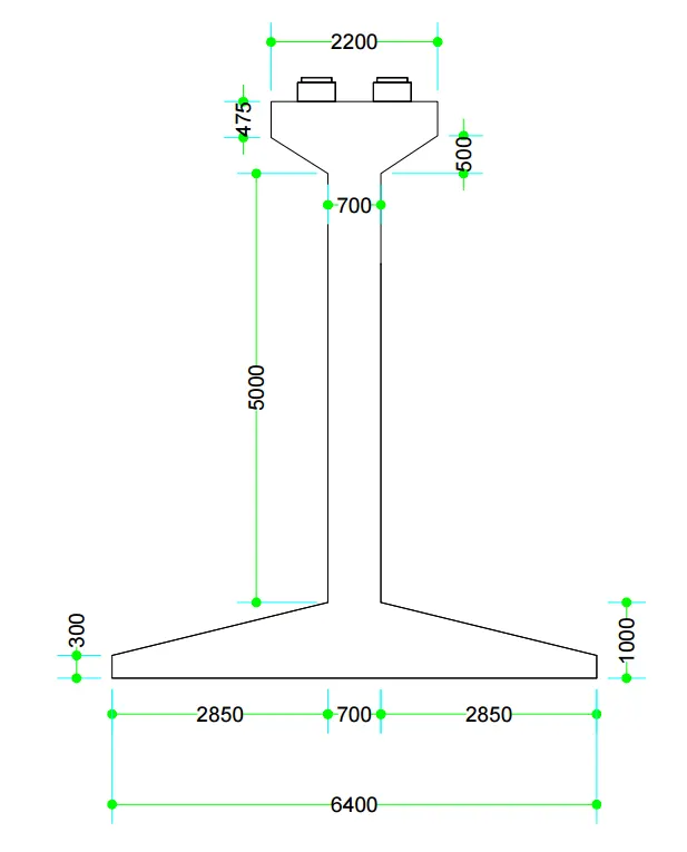
Pier Longitudinal View
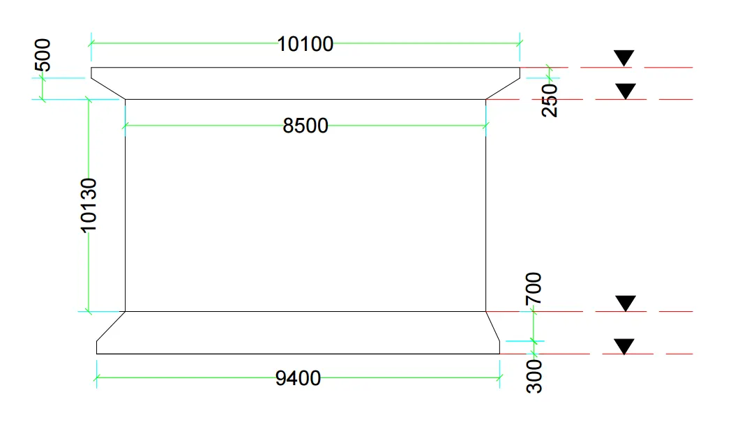
Transverse View of Pier
- Live load calcualtion:
| Load calculations from superstructure | ||||||
| Deal load of superstructure | ||||||
| Left Span | ||||||
| Total weight of super structure. | = | 199.00 | tonne | |||
| Reaction from left Span | Total Weight/2 | = | 99.50 | tonne | ||
| Reaction on Pier | (199/2) | = | 99.50 | tonne | ||
| Right Span | ||||||
| Total weight of super structure. | = | 199.00 | tonne | |||
| Reaction from left Span | Total Weight/2 | = | 99.50 | tonne | ||
| Reaction on Pier | (199/2) | = | 99.50 | tonne | ||
| Total Reaction on Pier | 199.00 | tonne | ||||
| Distance between bearing & Cl of Pier shaft | = | 0.50 | m | |||
| Longitudinal moment | (99.5*0.5)-(99.5*0.5) | = | - | t-m | ||
| Transverse eccentricity of dead load from c/l of Pier | = | - | m | |||
| Transverse moment. | (199*0) | = | - | t-m | ||
| SIDL(Crash barrier,railing,footpath)-Excluding Wearing Course | ||||||
| Left Span | ||||||
| Crash barrier Weight | Weight of C/B*Span*2 | = | 26.3 | t | ||
| Raling weigth | = | - | t | |||
| Footpath/services weight | = | - | t | |||
| Right Span | ||||||
| Crash barrier Weight | Weight of C/B*Span*2 | = | 26.3 | t | ||
| Raling weigth | = | - | t | |||
| Footpath/services weight | = | - | t | |||
| Total reaction on pier (SIDL Excl. W/C) | = | 26.33 | ||||
| Longitudinal moment (Crash Barrier) | = | - | t-m | |||
| Longitudinal moment (Railing) | = | - | t-m | |||
| Longitudinal moment (footpath/services) | = | - | t-m | |||
| Total Longitudinal moment(SIDL Excl. W/C) | = | - | t-m | |||
| Transverse eccentricity of C/B | = | - | m | |||
| Transverse moment of C/B | = | - | t-m | |||
| Transverse eccentricity of Railing | = | - | m | |||
| Transverse moment of Railing | = | - | t-m | |||
| Transverse eccentricity of footpath/services | = | - | m | |||
| Transverse moment of footpath/services | = | - | t-m | |||
| Total Transverse moment(SIDL Excl. W/C) | = | - | t-m | |||
| SIDL(Including Wearing Course | ||||||
| Left Span | ||||||
| Load Intensity due to wearing course | Weight of wc*span*cw | = | 0.14 | t/m2 | ||
| DL of Wearing Course | = | 20.92 | t | |||
| Right Span | ||||||
| DL of Wearing Course | = | 20.92 | t | |||
| Total reaction on abutment (SIDL excluding W/c) | (20.92/2)+(20.92/2) | = | 20.92 | t | ||
| Longitudinal Moment( wearing Course) | = | - | t-m | |||
| Transverse eccentricity of wearing Course | = | - | m | |||
| Transverse moment( wearing Course) | = | - | t-m | |||
| Summary of loads from superstructure | ||||||
| At Bearing Level | ||||||
| Load Item | Pmax | Pmin | ML | MT | HL | HT |
| t | t | t-m | t-m | t-m | t-m | |
| Deal Load | 199.00 | 199.00 | - | - | - | - |
| SIDL-Excluding W/C | 26.33 | 26.33 | - | - | - | - |
| SIDL-including W/C | 20.92 | 20.92 | - | - | - | - |
| At Pier shaft bottom level | ||||||
| Load Item | Pmax | Pmin | ML | MT | HL | HT |
| t | t | t-m | t-m | t-m | t-m | |
| Deal Load | 199.00 | 199.00 | - | - | 0 | 0 |
| SIDL-Excluding W/C | 26.33 | 26.33 | - | - | 0 | 0 |
| SIDL-including W/C | 20.92 | 20.92 | - | - | 0 | 0 |
| At Foundatiion bottom level | ||||||
| Load Item | Pmax | Pmin | ML | MT | HL | HT |
| t | t | t-m | t-m | t-m | t-m | |
| Deal Load | 199.00 | 199.00 | - | - | - | 0 |
| SIDL-Excluding W/C | 26.33 | 26.33 | - | - | - | 0 |
| SIDL-including W/C | 20.92 | 20.92 | - | - | - | 0 |
| One Span Dislodged Consition | ||||||
| Dead Load of super-structure | ||||||
| Vertical Load on Pier | = | 99.50 | t | |||
| Longitudinal Moment | = | 49.8 | t m | |||
| Transverse Moment | = | - | t m | |||
| SIDL(Crash barrier,railing,footpath)-Excluding Wearing Course | ||||||
| Vertical Load on Pier | = | 13.17 | t | |||
| Longitudinal Moment | = | 6.6 | t m | |||
| Transverse Moment | = | - | t m | |||
| SIDL(Including Wearing Course | ||||||
| Vertical Load on Pier | = | 10.46 | t | |||
| Longitudinal Moment | = | 5.2 | t m | |||
| Transverse Moment | = | - | t m | |||
| Summary of loads from superstructure | ||||||
| At Bearing Level | ||||||
| Load Item | Pmax | Pmin | ML | MT | HL | HT |
| t | t | t-m | t-m | t-m | t-m | |
| Deal Load | 99.50 | 99.50 | 49.75 | - | - | - |
| SIDL-Excluding W/C | 13.17 | 13.17 | 6.58 | - | - | - |
| SIDL-including W/C | 10.46 | 10.46 | 5.23 | - | - | - |
| At Pier shaft bottom level | ||||||
| Load Item | Pmax | Pmin | ML | MT | HL | HT |
| t | t | t-m | t-m | t-m | t-m | |
| Deal Load | 99.50 | 99.50 | 49.75 | - | 0 | 0 |
| SIDL-Excluding W/C | 13.17 | 13.17 | 6.58 | - | 0 | 0 |
| SIDL-including W/C | 10.46 | 10.46 | 5.23 | - | 0 | 0 |
| At Foundatiion bottom level | ||||||
| Load Item | Pmax | Pmin | ML | MT | HL | HT |
| t | t | t-m | t-m | t-m | t-m | |
| Deal Load | 99.50 | 99.50 | 49.75 | - | - | 0 |
| SIDL-Excluding W/C | 13.17 | 13.17 | 6.58 | - | - | 0 |
| SIDL-including W/C | 10.46 | 10.46 | 5.23 | - | - | 0 |
| Live load calculation( Normal case) | ||||||
| Live load calculation | ||||||
| Following live load cases are considered | ||||||
| 1 lane 70R-wheeled | ||||||
| 1 lane Class A | ||||||
| 3 lane class-A | ||||||
| 1 lane 70R-wheeled+1 lane Class-A | ||||||
| Left Span | ||||||
| Reaction due to DL+SIDL | = | 146.75 | t | |||
| Right Span | ||||||
| Reaction due to DL+SIDL | = | 146.75 | t | |||
| Bearing Type | Elastomeric | |||||
| 1 lane 70R0 wheeled | Both Span Loaded | |||||
| Live load Reactions | ||||||
| Rb | (49*9.48)/(9.48+3.32-0.5) | = | 37.75 | t | ||
| Rc | (51*9.61)/(9.61+3.19-0.5) | = | 39.83 | t | ||
| Total Load of 70R vehicle | = | 77.58 | t | |||
| Total Load of 70R vehicle according this span | = | 77.58 | t | |||
| Total Load (including Impact) | (77.58*1.25) | = | 96.97 | t | ||
| Live load Reactions with impact factor | Rb | 47.19 | t | |||
| Live load Reactions with impact factor | Rc | 49.79 | t | |||
| longitudinal moment | = | 1.30 | t-m | |||
| total length of 70R vehicle | 3.96+1.52+2.13+1.37+3.05+1.37 | = | 13.400 | m | ||
| CG Calculation | (8*0+12*3.96+12*5.48+17*7.61+17*8.98+17*12.03+17*13.4)/100 | = | 8.276 | m | ||
| Braking Force | (96.97* of 20%) | = | 19.39 | t | ||
| Change in reaction due to braking force | (19.39*(1.2+230.115-228.458)/13.4) | = | 4.14 | t | ||
| Total Horozontal force at bearing level | Fh/2 | = | 9.7 | t | ||
| Total Horozontal force (Longitudinal) | HL | = | 9.7 | t | ||
| Total Horozontal force (transverse) | HT | = | - | t | ||
| Transverse Eccentricity | (12/2-(1.2+0.5+2.79/2) | = | 2.905 | m | ||
| Transverse Moment on abutment | MT | = | 281.71 | t-m | ||
| 1 lane Class - A | Cl204,IRC:6-2014 | |||||
| Live load Reactions | ||||||
| Rb | (28.2*7.78)/(7.78+5.02-0.5) | = | 17.83 | t | ||
| Rc | (27.2*7.59)/(7.59+5.21-0.5) | = | 16.79 | t | ||
| Total Load of 70R vehicle | = | 34.61 | t | |||
| Total Load of 70R vehicle according this span | = | 34.61 | t | |||
| Total Load (including Impact) | (34.61*1.25) | = | 43.27 | t | ||
| Live load Reactions with impact factor | Rb | 22.28 | t | |||
| Live load Reactions with impact factor | Rc | 20.98 | t | |||
| longitudinal moment | = | 0.65 | t-m | |||
| total length of 70R vehicle | = | 18.800 | m | |||
| CG Calculation | = | 9.091 | m | |||
| Braking Force | (43.27* of 20%) | = | 8.65 | t | ||
| Change in reaction due to braking force | = | 1.32 | t | |||
| Total Horozontal force at bearing level | Fh/2 | = | 4.3 | t | ||
| Total Horozontal force (Longitudinal) | HL | = | 4.3 | t | ||
| Total Horozontal force (transverse) | HT | = | - | t | ||
| Transverse Eccentricity | (12/2-(0.15+0.5+2.3/2) | = | 4.20 | m | ||
| Transverse Moment | = | 181.7 | t-m | |||
| 3 lane Class - A | ||||||
| Live load Reactions | ||||||
| Ra | (3*17.83*1.25* of 90%) | = | 60.17 | t | ||
| Rb | (3*16.79*1.25 of 90%) | = | 56.66 | t | ||
| Vertical reaction on Pier | = | 116.82 | t | |||
| longitudinal moment | = | 1.76 | t-m | |||
| Braking Force | (20% of 34.61+ 5% of 34.61%)*90% | = | 6.99 | t | ||
| Total Braking force at bearing level | = | 1.63 | t | |||
| Total Horozontal force at bearing level | Fh/2 | = | 3.5 | t | ||
| Total Horozontal force (Longitudinal) | HL | = | 3.5 | t | ||
| Total Horozontal force (transverse) | HT | = | - | t | ||
| Transverse Eccentricity | 12/2-.5-.15-2.3-1.2-2.3/2 | = | 0.70 | m | ||
| Transverse Moment | = | 81.8 | t-m | |||
| 1 lane 70R +1 lane Class - A | ||||||
| Live load Reactions | ||||||
| Rb | 90% of (37.75*1.25+ 17.83*1.25) | = | 87.28 | t | ||
| Rc | 90% of (39.83*1.25+ 16.79*1.25) | = | 63.69 | t | ||
| Vertical reaction on Pier | = | 150.97 | t | |||
| Braking Force | (20% of 96.97+ 5% of 43.27%)*90% | = | 19.40 | t | ||
| Total Braking force at bearing level | = | 4.5 | t | |||
| longitudinal moment | = | 54.93 | t-m | |||
| Total Horozontal force at bearing level | Fh/2 | = | 9.70 | t | ||
| Total Horozontal force (Longitudinal) | HL | = | 9.70 | t | ||
| Total Horozontal force (transverse) | HT | = | - | t | ||
| Transverse Eccentricity of 70R-W | 12/2-(0.5+1.2+2.79/2) | = | 2.905 | m | ||
| Transverse Eccentricity of Class-A | 12/2-6.84 | = | -0.84 | m | ||
| Total Transverse Moment | MT | = | 200.04 | t-m | ||
| One Span Loaded | ||||||
| 1 lane 70R Wheeled | ||||||
| Left Span | ||||||
| Load On Left Span | = | - | t | |||
| Right Span | ||||||
| Live load Reactions | ||||||
| Vertical Load on pier | = | 78.50 | t | |||
| longitudinal moment | = | 39.25 | t-m | |||
| Live load Reactions with impact factor | Rb | - | t | |||
| Live load Reactions with impact factor | Rc | 98.12 | t | |||
| Braking Force | = | 15.70 | t | |||
| Total braking force at bearing level | = | 4.51 | t | |||
| Total Horozontal force (Longitudinal) | HL | = | 7.8 | t | ||
| Total Horozontal force (transverse) | HT | = | - | t | ||
| Transverse Eccentricity | (12/2-(1.2+0.5+2.79/2) | = | 2.905 | m | ||
| Transverse Moment on abutment | MT | = | 228.04 | t-m | ||
| 1 lane Class A- Wheeled | ||||||
| Left Span | ||||||
| Load On Left Span | = | - | t | |||
| Right Span | ||||||
| Load On right Span include impact factor | = | 48.25 | t | |||
| Live load Reactions | ||||||
| Rb | = | - | t | |||
| Rc | = | 22.36 | t | |||
| Vertical Load on pier | = | 22.36 | t | |||
| longitudinal moment | = | 11.18 | t-m | |||
| Live load Reactions with impact factor | Rb | - | t | |||
| Live load Reactions with impact factor | Rc | 27.95 | t | |||
| Braking Force | = | 4.47 | t | |||
| Total braking force at bearing level | = | 1.04 | t | |||
| Total Horozontal force (Longitudinal) | HL | = | 2.2 | t | ||
| Total Horozontal force (transverse) | HT | = | - | t | ||
| Transverse Eccentricity | (12/2-(0.15+0.5+2.3/2) | = | 4.20 | m | ||
| Transverse Moment on pier | MT | = | 202.65 | t-m | ||
| Figure: | ||||||
| 3 lane Class - A | ||||||
| Live load Reactions | ||||||
| Ra | Include impact factor 25% | = | - | t | ||
| Rb | Include impact factor 25% | = | - | t | ||
| Rc | Include impact factor 25% | (3*0*1.25* of 90%) | = | 162.84 | ||
| Rd | Include impact factor 25% | (3*0*1.25 of 90%) | = | - | ||
| Vertical reaction on Pier | = | 162.84 | t | |||
| longitudinal moment | = | 81.42 | t-m | |||
| Braking Force | (20% of 38.6+ 5% of 38.6%)*90% | = | 9.65 | t | ||
| Total Braking force at bearing level | = | 2.26 | t | |||
| Total Horozontal force at bearing level | Fh/2 | = | 4.8 | t | ||
| Total Horozontal force (Longitudinal) | HL | = | 4.8 | t | ||
| Total Horozontal force (transverse) | HT | = | - | t | ||
| Transverse Eccentricity | 12/2-.5-.15-2.3-1.2-2.3/2 | = | 0.70 | m | ||
| Transverse Moment | = | 114.0 | t-m | |||
| 1 lane 70R+1 lane Class A- (Wheeled) | ||||||
| Live load Reactions | ||||||
| Rb | Include impact factor 25% | = | - | t | ||
| Rc | Include impact factor 25% | = | 131.74 | |||
| Vertical reaction on Pier | = | 131.74 | t | |||
| longitudinal moment | = | 65.87 | t-m | |||
| Braking Force | = | 26.35 | t | |||
| Total Braking force at bearing level | = | 6.16 | t | |||
| Total Horozontal force at bearing level | Fh/2 | = | 13.2 | t | ||
| Total Horozontal force (Longitudinal) | HL | = | 13.2 | t | ||
| Total Horozontal force (transverse) | HT | = | - | t | ||
| Transverse Eccentricity of Class A | = | 4.20 | m | |||
| Transverse Eccentricity of 70R | = | 0.455 | m | |||
| Transverse Moment | = | 316.5 | t-m | |||
| Summary | ||||||
| Both Span Loaded | ||||||
| Load Item | Pmax | Pmin | ML | MT | HL | HT |
| t | t | t-m | t-m | t | t | |
| 1 lane 70R -W | 96.97 | 96.97 | 1.30 | 281.71 | 9.70 | - |
| I lane Class-A | 43.27 | 43.27 | 0.65 | 181.73 | 4.33 | - |
| 3 lanes Class-A | 116.82 | 116.82 | 1.76 | 81.78 | 3.49 | - |
| 1 lane 70R -W+I lane Class-A | 150.97 | 150.97 | 54.93 | 200.04 | 9.70 | - |
| One Span Loaded | ||||||
| Load Item | Pmax | Pmin | ML | MT | HL | HT |
| t | t | t-m | t-m | t | t | |
| 1 lane 70R -W | 78.50 | 78.50 | 39.25 | 228.04 | 7.85 | - |
| I lane Class-A | 48.25 | 48.25 | 11.18 | 202.65 | 2.24 | - |
| 3 lanes Class-A | 162.84 | 162.84 | 81.42 | 113.99 | 4.83 | - |
| 1 lane 70R -W+I lane Class-A | 131.74 | 131.74 | 65.87 | 316.48 | 13.17 | - |
| Final Summary | ||||||
| Normal Case | ||||||
| Bearing Level | ||||||
| Load Item | Pmax | Pmin | ML | MT | HL | HT |
| t | t | t-m | t-m | t | t | |
| LL1 | 150.97 | 150.97 | 82.65 | 200.04 | 9.70 | 0.00 |
| LL2 | 162.84 | 162.84 | 95.21 | 113.99 | 4.83 | - |
| LL3 | 116.82 | 116.82 | 11.74 | 81.78 | 3.49 | - |
| Pier bottom Level | ||||||
| Load Item | Pmax | Pmin | ML | MT | HL | HT |
| t | t | t-m | t-m | t | t | |
| LL1 | 150.97 | 150.97 | 202.90 | 200.04 | 9.70 | 0.00 |
| LL2 | 162.84 | 162.84 | 155.02 | 113.99 | 4.83 | - |
| LL3 | 116.82 | 116.82 | 55.04 | 81.78 | 3.49 | - |
| Foundation bottom Level | ||||||
| Load Item | Pmax | Pmin | ML | MT | HL | HT |
| t | t | t-m | t-m | t | t | |
| LL1 | 150.97 | 150.97 | 224.27 | 200.04 | 9.70 | 0.00 |
| LL2 | 162.84 | 162.84 | 165.64 | 113.99 | 4.83 | - |
| LL3 | 116.82 | 116.82 | 62.73 | 81.78 | 3.49 | - |
Water Current forces calcualation:
Wind force Culacualtion:-
| - | Calcualtion of Wind forces | ||||||||
| - | Basic Wind Speed | = | 50 | m/s | |||||
| - | Type of terrain | = | Plain Terrain | ||||||
| - | Type of Super-Structure | = | RCC Girder & Deck | ||||||
| - | Type of Sub-strucutre | ||||||||
| - | The average Height in m of exposed surfacce above GL, Bed lvl. & LWL | = | H | ||||||
| - | Hourly Mean speed of wind in m/s at Height H | = | Vz | ||||||
| - | Horoizontal Wind pressure in N/m2 at Height H | = | Pz | ||||||
| - | Calcualtion of wind forces on superstructure | ||||||||
| - | Skew Angle | = | 0 | 0 | Radian | ||||
| - | Left Span | ||||||||
| - | Length of superstructure in L_L direction (sq) | = | 13.30 | m | Span Exp.to Exp C/C | ||||
| - | Length of superstructure in L_L direction (skew) | = | 13.30 | m | |||||
| - | Length of superstructure in T_T direction (sq) | = | 12.00 | m | |||||
| - | Total Depth of Surestructure include Crash barrier | = | 2.22 | m | |||||
| - | The average Height in m of exposed surfacce from Pier cap to MSL | = | 9.131 | m | |||||
| - | From IRC:6-2017, Table 12, page no 33 | Vz | = | 42.1 | m/s | ||||
| - | Pz | = | 1064.5 | N/m2 | |||||
| - | Wind Forces on DL+SIDL | ||||||||
| - | Gust Factor | G | = | 2 | Cl.209.3.3 | ||||
| - | Drag Co-efficeint | CD | = | 1.3 | |||||
| - | Expossed Solid Area | A1 | = | 29.526 | m2 | ||||
| - | Force intransverse Direction | FT | = | Pz*A1*G*CD | |||||
| - | = | 81,719.11 | N | ||||||
| - | = | 81.72 | kN | ||||||
| - | FT | = | 8.17 | t | |||||
| - | acting at RL | = | 229.568 | m | |||||
| - | |||||||||
| - | Force in Longitudinal Direction | FL | = | 2.04 | t | ||||
| - | 25 % of Transverse Force(FT) | IRC 6-2020,Cl.209.3.4 | |||||||
| - | acting at RL | = | 229.568 | m | |||||
| - | |||||||||
| - | Plan Area | A2 | = | 159.60 | m2 | ||||
| - | Lift Co-efficient | Fuplift | = | 0.75 | Cl.209.3.5,IRC6 | ||||
| - | |||||||||
| - | Force in Vertical l Direction | FL | = | Pz*A1*G*CL | |||||
| - | FL | = | -2,54,841.30 | N | |||||
| - | -25.48413 | t | |||||||
| - | Wind forces on Live load | ||||||||
| - | height fo ddeck surface from GL | = | 5.937 | m | |||||
| - | Wind speed at deck Level | VZ | = | 42.1 | m/s | Cl.209.3.7,IRC6 | |||
| - | No live load should be considered on deck | ||||||||
| - | height of live load above roadway surface | = | 3 | m/s | Cl.209.3.6,IRC6 | ||||
| - | Gust Factor | G | = | 2 | |||||
| - | Drag Co-efficeint | CD | = | 1.2 | |||||
| - | Expossed Solid Area | A1 | = | 0 | m2 | ||||
| - | |||||||||
| - | Force in transverse Direction | FT | = | Pz*A1*G*CD | Cl.209.3.3,IRC6 | ||||
| - | = | 0 | t | ||||||
| - | Acting at RL | = | 231.615 | m | |||||
| - | Total Wind forces at bearing level from superstructure | ||||||||
| - | Both Span | One Span (RHS Span) | |||||||
| - | FT | = | 8.2 | t | FT | 4.09 | t | ||
| - | FL | = | 2.04 | t | FL | 1.02 | t | ||
| - | Fuplift | = | -25.48 | t | FL | -12.74 | t | ||
| - | |||||||||
| - | |||||||||
| - | Force at bearing Level ( BS Span) | ||||||||
| - | |||||||||
| - | HL Wind | = | FL cos𝜃-FT sin𝜃 | ||||||
| - | HT Wind | = | FL sin𝜃+FT cos𝜃 | ||||||
| - | P wind | = | Fuplift | ||||||
| - | |||||||||
| - | Both Span | One Span (RHS Span) | |||||||
| - | HL Wind | = | 2. t | HL Wind | = | 1. t | |||
| - | HT Wind | = | 8.2 t | HT Wind | = | 4.1 t | |||
| - | P wind | = | -25.5 t | P wind | = | -12.7 t | |||
| - | |||||||||
| - | Forces at pier shaft bottom level due to wind forces on superstructure | ||||||||
| - | Both Span present | One Span (RHS Span present) | |||||||
| - | P wind | = | -25.5 t | P wind | = | -12.7 t | |||
| - | HL Wind | = | 2. t | HL Wind | = | 1. t | |||
| - | HT Wind | = | 8.2 t | HT Wind | = | 4.1 t | |||
| - | ML due to HL | = | 22.9 t-m | ML due to HL | = | 11.4 t-m | |||
| - | ML due to P wind | = | . t-m | ML due to P wind | = | . t-m | |||
| - | MT due to HT | = | 91.5 t-m | MT due to HT | = | 45.7 t-m | |||
| - | |||||||||
| - | |||||||||
| - | Calculation of Wind forces on Sub-structure | ||||||||
| - | <!-- [if gte vml 1]>
|
||||||||
| - | |||||||||
| - | |||||||||
| - | |||||||||
| - | |||||||||
| - | |||||||||
| - | |||||||||
| - | Area of Rectangular part | A1 | = | 0.55 | m2 | ||||
| - | Area of Trapezoidal Part | A2 | = | 0.725 | m2 | ||||
| - | Total Area | A=(A1+A2) | 1.275 | m2 | |||||
| - | |||||||||
| - | = | ||||||||
| - | CG of Rectangular part | = | 0.1250 | m | |||||
| - | CG of Trapezoidal Part | 0.2069 | m | ||||||
| - | |||||||||
| - | Moment of rectangular area | = | 0.06875 | m3 | |||||
| - | Moment of Trapezoidal area | = | 0.17586207 | m3 | |||||
| - | CG of the section fom top | = | 0.22978364 | m | |||||
| - | = | ||||||||
| - | = | ||||||||
| - | Average height of exposed surface from GL to Pier cap top Level | = | 3.73521636 | ||||||
| - | hourly mean Wind Speed | Vz | = | 42.1 | m/s | from code | |||
| - | Hourly mean Wind pressure | Pz | = | 1064.5 | N/m2 | from code | |||
| - | Exposed solid area | A | = | 1.275 | m2 | ||||
| - | Gust Factor | G | = | 2 | |||||
| - | Drag Co-efficeint | CD | = | 1.2 | |||||
| - | |||||||||
| - | Width of Cap(Skew) | b | = | 2.2 | m | ||||
| - | Length of Cap(Skew) | t | = | 10.1 | m | ||||
| - | t/b | = | 4.59 | ||||||
| - | Height/Breadth | = | 0.34 | ||||||
| - | Force intransverse Direction | FT | = | Pz*A1*G*CD | |||||
| - | = | 3,257.37 | N | ||||||
| - | FT | = | 0.33 | t | |||||
| - | acting at RL | = | 227.913 | m | |||||
| - | Total Wind forces at bearing level from pier cap | ||||||||
| - | HL Wind | = | `-FT sin𝜃 | = | - | t | |||
| - | HT Wind | = | FT cos𝜃 | = | 1.0 | t | |||
| - | ML | ` | - | t | |||||
| - | MT | = | 10.88 | t-m | |||||
| - | |||||||||
| - | Calculation of Wind forces on Pier Shaft | ||||||||
| - | Pier Shaft | <!-- [if gte vml 1]> |
|||||||
| - | |||||||||
| - | |||||||||
| - | |||||||||
| - | |||||||||
| - | |||||||||
| - | |||||||||
| - | |||||||||
| - | |||||||||
| - | |||||||||
| - | Average height of exposed surface from GL | ||||||||
| - | = | 9.131 | m | ||||||
| - | hourly mean Wind Speed | Vz | |||||||
| - | Hourly mean Wind pressure | Pz | = | 42.1 | m/s | ||||
| - | Exposed Solid area LWL Case | A1 | = | 1064.5 | N/m2 | ||||
| - | Gust factor | G | = | 6.39 | m2 | ||||
| - | Height/breadth | = | 2.00 | ||||||
| - | Drag Co-effient | CD | = | 13.04 | |||||
| - | t/b | = | 1.20 | ||||||
| - | Force intransverse Direction | FT | = | 13.14 | |||||
| - | = | Pz*A1*G*CD | |||||||
| - | FT | = | 16,329.515 | N | |||||
| - | acting at RL | = | 1.63 | t | |||||
| - | Forces at footing bottom level due to wind forces on pier shaft | = | 228.74 | m | |||||
| - | HL Wind | = | `-FT sin𝜃 | ||||||
| - | HT Wind | = | FT cos𝜃 | = | - | t | |||
| - | ML | = | 6.1 | t | |||||
| - | MT | = | - | t | |||||
| - | = | 76.14 | t-m | ||||||
| - | Summary of Forces due to Wind on super-structure+Sub-structure | ||||||||
| - | Both Span present | ||||||||
| - | At Pier bottom level | ||||||||
| - | Pmax | Pmin | ML | MT | HL | HT | |||
| - | t | t | t-m | t-m | t | t | |||
| - | 25.48 | -25.48 | 22.87 | 91.49 | 2.04 | 8.17 | |||
| - | |||||||||
| - | At Footing bottom level | ||||||||
| - | Pmax | Pmin | ML | MT | HL | HT | |||
| - | t | t | t-m | t-m | t | t | |||
| - | 25.48 | -25.48 | 24.92 | 99.66 | 2.04 | 8.17 | |||
| - | |||||||||
| - | Single Span present | ||||||||
| - | At Pier bottom level | ||||||||
| - | Pmax | Pmin | ML | MT | HL | HT | |||
| - | t | t | t-m | t-m | t | t | |||
| - | 12.74 | -12.74 | 11.44 | 45.75 | 1.02 | 4.09 | |||
| - | |||||||||
| - | At Footing bottom level | ||||||||
| - | Pmax | Pmin | ML | MT | HL | HT | |||
| - | t | t | t-m | t-m | t | t | |||
| - | 12.74 | -12.74 | 12.46 | 49.83 | 1.02 | 4.09 | |||
Load Combination:
| Load Combiantion LSM Annexure B,IRC :6-220 | ||||||||||
| Following Load Combiantions are considered | ||||||||||
| A | Ultimate Limit State( for Verification of structural Strength ) | |||||||||
| A-1 | Basic Combination | |||||||||
| A-2 | Seismic Combination | |||||||||
| B | Serviceability Limit State | |||||||||
| B-1 | Rare combination( For checking stress limit) | |||||||||
| B-2 | Quasi-Peermanent Combination(For Checkong crack width in RCC structure) | |||||||||
| C | Combiantion Base Pressure & design of Foundation | |||||||||
| C-1 | Combiantion-1 | |||||||||
| C-2 | Combiantion-2 | |||||||||
| C-3 | Combiantion-3 | |||||||||
| - | Load Combiantion- Base Pressure Check | |||||||||
| - | Combination for base Pressure | |||||||||
| - | Normal Case | |||||||||
| - | Both Span present | |||||||||
| - | LWL without Scour | Unfactored forces | ||||||||
| - | Load Item | Pmax | Pmin | ML | MT | HL | HT | |||
| - | t | t | t-m | t-m | t | t | ||||
| - | DL(Superstructure) | 199.00 | 199.00 | - | - | - | - | |||
| - | SIDL (Excluding w/c) | 26.33 | 26.33 | - | - | - | - | |||
| - | SIDL(Including w/c) | 20.92 | 20.92 | - | - | - | - | |||
| - | LL1-Max. reaction case | 150.97 | 150.97 | 224.27 | 200.04 | 9.70 | 0.00 | |||
| - | Substructure Weight | 199.42 | 199.42 | - | - | - | - | |||
| - | Weight of soil on footing | 761.10 | 761.10 | - | - | - | - | |||
| - | Weight of Foooting | 105.05 | - | - | - | - | - | |||
| - | Wind Load | 25.48 | -25.48 | 22.87 | 91.49 | 2.04 | 8.17 | |||
| - | Total for unfortored loads | 1,488.27 | 1,332.26 | 247.14 | 291.53 | 11.74 | 8.17 | |||
| - | ||||||||||
| - | LL2-max. Longitudinal Moment Case | Unfactored forces | ||||||||
| - | Load Item | Pmax | Pmin | ML | MT | HL | HT | |||
| - | t | t | t-m | t-m | t | t | ||||
| - | DL(Superstructure) | 199.00 | 199.00 | - | - | - | - | |||
| - | SIDL (Excluding w/c) | 26.33 | 26.33 | - | - | - | - | |||
| - | SIDL(Including w/c) | 20.92 | 20.92 | - | - | - | - | |||
| - | LL2-max. Longitudinal Moment Case | 162.84 | 162.84 | 165.64 | 113.99 | 4.83 | - | |||
| - | Substructure Weight | 199.42 | 199.42 | - | - | - | - | |||
| - | Weight of soil on footing | 761.10 | 761.10 | - | - | - | - | |||
| - | Weight of Foooting | 105.05 | - | - | - | - | - | |||
| - | Wind Load | 25.48 | -25.48 | 22.87 | 91.49 | 2.04 | 8.17 | |||
| - | Total for unfortored loads | 1,500.14 | 1,344.13 | 188.52 | 205.48 | 6.87 | 8.17 | |||
| - | ||||||||||
| - | LL3-max. Transverse Moment Case | Unfactored forces | ||||||||
| - | Load Item | Pmax | Pmin | ML | MT | HL | HT | |||
| - | t | t | t-m | t-m | t | t | ||||
| - | DL(Superstructure) | 199.00 | 199.00 | - | - | - | - | |||
| - | SIDL (Excluding w/c) | 26.33 | 26.33 | - | - | - | - | |||
| - | SIDL(Including w/c) | 20.92 | 20.92 | - | - | - | - | |||
| - | LL3-max. Transverse Moment Case | 116.82 | 116.82 | 62.73 | 81.78 | 3.49 | - | |||
| - | Substructure Weight | 199.42 | 199.42 | - | - | - | - | |||
| - | Weight of soil on footing | 761.10 | 761.10 | - | - | - | - | |||
| - | Weight of Foooting | 105.05 | - | - | - | - | - | |||
| - | Wind Load | 25.48 | -25.48 | 22.87 | 91.49 | 2.04 | 8.17 | |||
| - | Total for unfortored loads | 1,454.12 | 1,298.11 | 85.60 | 173.27 | 5.54 | 8.17 | |||
| - | ||||||||||
| - | One Span dislodged Condition | |||||||||
| - | Load Item | Unfactored forces | ||||||||
| - | Pmax | Pmin | ML | MT | HL | HT | ||||
| - | t | t | t-m | t-m | t | t | ||||
| - | DL(Superstructure) | 199.00 | 199.00 | - | - | - | - | |||
| - | SIDL (Excluding w/c) | 26.33 | 26.33 | - | - | - | - | |||
| - | SIDL(Including w/c) | 20.92 | 20.92 | - | - | - | - | |||
| - | Substructure Weight | 199.42 | 199.42 | - | - | - | - | |||
| - | Weight of soil on footing | 761.10 | 761.10 | - | - | - | - | |||
| - | Weight of Foooting | 105.05 | - | - | - | - | - | |||
| - | Wind Load | 25.48 | -25.48 | 22.87 | 91.49 | 2.04 | 8.17 | |||
| - | Total for unfortored loads | 1,337.30 | 1,181.29 | 22.87 | 91.49 | 2.04 | 8.17 | |||
| - | ||||||||||
| - | ||||||||||
| - | ||||||||||
| - | ||||||||||
| - | Summary of Load case for normal case | |||||||||
| - | LWL Case without Scour | |||||||||
| - | Both Span present | |||||||||
| - | Load case | Pmax | Pmin | ML | MT | HL | HT | |||
| - | t | t | t-m | t-m | t | t | ||||
| - | N1 | 1,488.27 | 1,332.26 | 247.14 | 291.53 | 11.74 | 8.17 | |||
| - | N2 | 1,500.14 | 1,344.13 | 188.52 | 205.48 | 6.87 | 8.17 | |||
| - | N3 | 1,454.12 | 1,298.11 | 85.60 | 173.27 | 5.54 | 8.17 | |||
| - | ||||||||||
| - | One Span dislodged condition | |||||||||
| - | Load case | Pmax | Pmin | ML | MT | HL | HT | |||
| - | t | t | t-m | t-m | t | t | ||||
| - | N4 | 1,337.30 | 1,181.29 | 22.87 | 91.49 | 2.04 | 8.17 | |||
| - | ||||||||||
| - | ||||||||||
| - | Base Pressure Check | |||||||||
| - | Area of Footing | A | = | 61.1 | m2 | |||||
| - | Section Modulus in Trans. Direction | Zt | = | 95.72 | m3 | |||||
| - | Section Modulus in Longi.. Direction | Zl | = | 66.19 | m3 | |||||
| - | ||||||||||
| - | Load Case No | Pmax | Pmin | ML | MT | P/A+ML/Zl+MT/Zt | P/A+ML/Zl-MT/Zt | P/A-ML/Zl-MT/Zt | P/A-(ML/Zl+MT/Zt) | Check |
| - | N1 | 1,488.27 | 1,332.26 | 247.14 | 291.53 | 31.14 | 25.05 | 17.58 | 23.67 | Ok |
| - | N2 | 1,500.14 | 1,344.13 | 188.52 | 205.48 | 29.55 | 25.25 | 19.56 | 23.85 | Ok |
| - | N3 | 1,454.12 | 1,298.11 | 85.60 | 173.27 | 26.90 | 23.28 | 20.70 | 24.32 | Ok |
| - | N4 | 1,337.30 | 1,181.29 | 22.87 | 91.49 | 23.19 | 21.28 | 20.59 | 22.50 | Ok |
Basic Comb for Design Foundation:
Design of Flexure:-
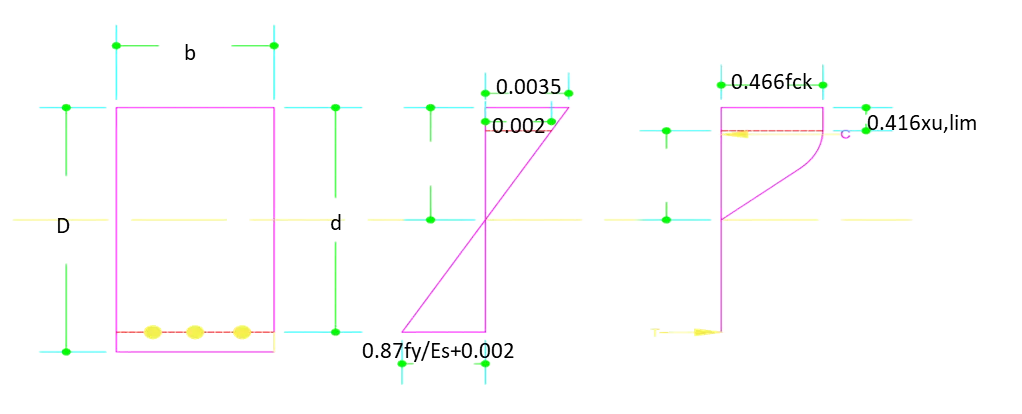
| Properties of Concrete | ||||||||||||
| Grade of Concrete | From IRC 112,Table 6.5 | = | 35.00 | |||||||||
| Characteristic Strength of Concrete | fck | = | 35.00 | Mpa=N/mm2 | ||||||||
| Design compressive Strength of Concrete | fcd | = | 15.63 | Mpa | ||||||||
| Tensile Strength of Concrete | fctm | = | 2.80 | Mpa | ||||||||
| Momulus of Elasticity of Concrete | <!-- [if gte vml 1]>
|
= | 32,000.00 | Mpa | ||||||||
| Partial Materials Safety Factor for Concrete | 𝛾𝑚 | = | 1.50 | |||||||||
| Ultimate Compressive strain in the concrete | <!-- [if gte vml 1]> |
= | 0.00 | |||||||||
| Constant | α | = | 0.67 | |||||||||
| Properties of Steel | ||||||||||||||||
| Grade of Steel | = | 500.00 | ||||||||||||||
| Characteristic Strength of Steel | fyk | = | 500.00 | Mpa=N/mm2 | ||||||||||||
| Momulus of Elasticity of Steel | Es | = | 2,00,000.00 | Mpa | ||||||||||||
| Partial Materials Safety Factor for Steel | <!-- [if gte vml 1]>
|
𝛾s | = | 1.15 | ||||||||||||
| Ultimate Compressive strain in the Steel | = | 0.00 | ||||||||||||||
| Design Yield Strength | fyd | = | 434.78 | Mpa | ||||||||||||
| Compressive force | ||||||
| Cu | = | 0.36*fck*b*xulim | ||||
| = | 17/21*fcd*b*xu,lim | |||||
| = | 0.80952*fcd*b*xu,lim | |||||
| Tensile force | ||||||
| Tu | = | .87*fy*Ast | ||||
| So, Limiting Resistance is equal to limiting moment | ||||||
| Rlim | = | Mu,lim/bd2 | = | 0.36*fck*Xu,lim/d(1-.429Xu,lim/d) | ||
| = | 5.78 | |||||
| For Fe500, Xu,lim/d | = | 0.62 | ||||
| Design Moment,Mu | = | 15.45 | ||||
| Overall Depth D | = | 1,000.00 | ||||
| Equivalent width of rectangular section | = | 1,425.00 | ||||
| d required | = | 137.00 | ||||
| d provided | = | 925.00 | ||||
| Moment of Resistance, R | = | 0.13 | ||||
| Ast,required | = | 385.76 | ||||
| Limiting Percentage of steel reinforcement for balanced Section | ||||||
| (𝑝𝑡,𝑙𝑖𝑚) | = | 38,576.01 | ||||
| Ast,required | per meter width | = | 270.71 | |||
| Minimum Ast,required | per meter width | = | 1,551.20 | |||
| Governing Ast,required | per meter in central bandwitch | = | 1,551.20 | |||
| Provide of Reinforcement in remaining width | = | |||||
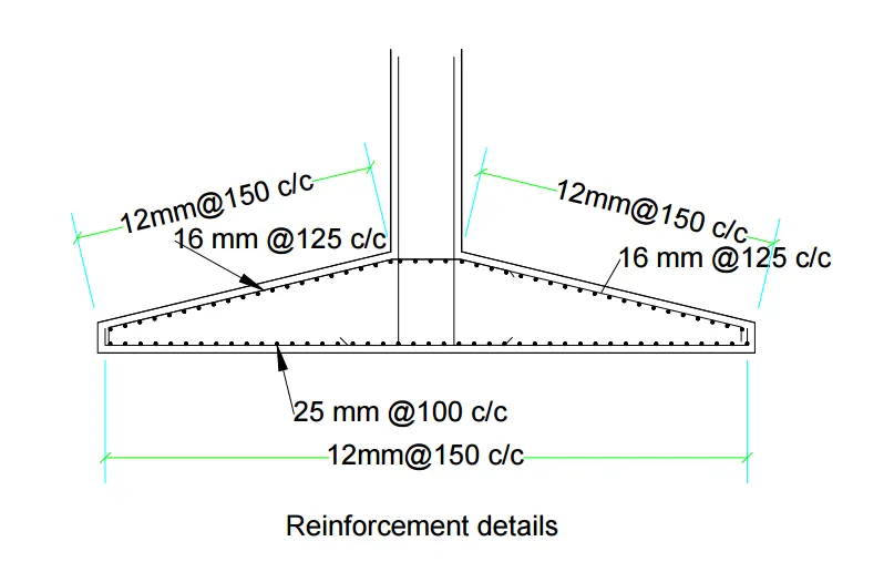
| Dia. Of Bar | 16 mm | + | mm | At Bottom | ||
| Spacing c/c | 125 mm | + | 125 mm | |||
| Ast,provided | = | 1,608.50 | ||||
| Percentage of Steel provided | = | 0.00 | ||||
| Max. Ast per meter width | Ast,max | = | 23,125.00 | |||
Reinforcement details :-
2. The difference between "free" and "fixed" piers in the context of foundation construction.
Explain the concepts and how they can impact foundation sizing:-
- <!-- [if !supportLists]-->Free Piers:
A free pier is a support column or pier that is not restrained laterally. In other words, it can move or sway horizontally (Longitudinal & Transverse Direction). Free piers are typically allowed to move independently due to factors like temperature changes, soil settlement, and other dynamic forces. They are usually used in situations where some degree of movement is expected and acceptable without compromising the stability or integrity of the structure.
- Fixed Piers:
A fixed pier, on the other hand, is a support column that is restrained laterally, preventing horizontal movement (Longitudinal & Transverse Direction). These piers are often used when there is a need to limit movement, such as in structures where even small horizontal shifts could lead to issues. Fixed piers are designed to resist lateral forces, and they provide a higher level of stability compared to free piers. The fixing of the pier's lateral movement can be achieved through various means, such as using foundation beams, tie beams, braces, or other structural elements.
Impact on Foundation Sizing:
The choice between free and fixed piers can have an impact on the design and sizing of the foundation. Here's how:
- Free Piers:
Since free piers are allowed to move, the foundation can be designed to accommodate some degree of settlement or lateral movement(Longitudinal & Transverse Direction). This might allow for a slightly simpler and more flexible foundation design, as it doesn't need to resist the same level of lateral forces.
- Fixed Piers:
Fixed piers require a more robust foundation design to resist lateral forces (Longitudinal & Transverse Direction) and prevent all those movement. The foundation needs to be designed to handle these additional loads and restraints, which might involve more complex calculations and potentially larger foundation elements.
- Conclusion:
In summary, the choice between free and fixed piers depends on the specific requirements and constraints of the project. Factors such as the level of lateral movement allowed, the structural stability needed, and the soil conditions at the construction site will influence the decision. The impact on foundation sizing will primarily be seen in the design and reinforcement of the foundation elements to accommodate the chosen type of pier.