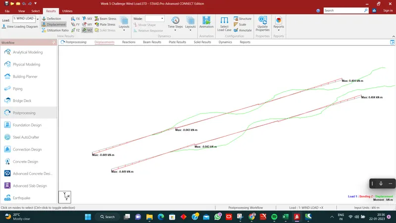
Week 5 Challenge
- Introduction:
Client Name (_______________________________________) has awarded Company Name ____________________________________ for Project Name(_____________________________________________________________________________________________________________________________________________________________________________________________________________________.
Company Name (______________________) has appointed INFRAENGG Design Agency’s name (__________________) as the “Design Consultant” to carry out the Detailed Design of the project corridor.
- Schedule of Spans & Dimensions:
Calculate the design wind loads for the bridges to be designed as follow:-
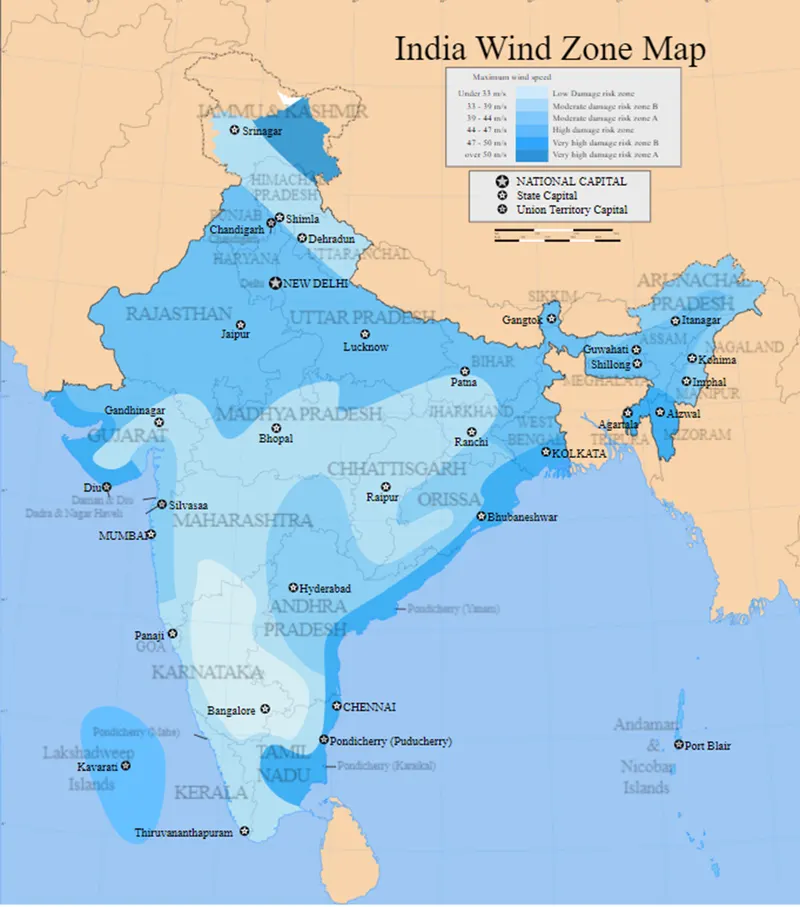
Zone : Mumbai
Height of the Bridge above GL : 9 m
Location : Open Terrain
Obstruction of Height less than : 10 m
The Pier Dimension : 5m x 1.5 m
Type of applied Load : Wind Load
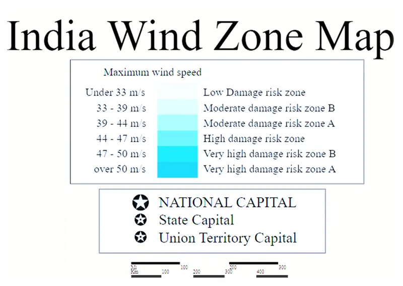
Consider zone as per Map : B
Basic Wind Speed (Vb) : 44 m/s,(Annex-A,(Clause 6.2), Page No-51)
As per IS Code 875-part 3-2015, Table No-01
And clause No- 5.3.1; Page No-11
- Value of K1 : 07
Height is 9 m & Category , class A,
K2 factor is taken……
As per IS Code 875-part 3-2015, Table No-02
And clause No- 5.3.2.2, Page No-12, K2 factor is taken.
- Value of K2 : 1.00
As per IS Code 875-part 3-2015, Table No-02,
For Upwind Slope is less than 30
And clause No- 5.3.2.2, Page No-12; K3 factor is taken.
- Value of K3 : 1.00
As per IS Code 875-part 3-2015,
The Location is within 56 km radius of the Ocean, so cyclone factor is taken 1.3
And clause No- 5.3.3.1, Page No-13; K4 factor is taken.
- Value of K4 : 1.3
|
|
|||||||||
|
Input Data |
Symbol |
Value |
Unit |
Reference From IS 875 Part-3(2015) |
|||||
|
Clause No |
Page No |
Note |
|||||||
|
Basic Wind Speed |
Vb |
: |
44.00 |
m/s |
|||||
|
K1 factor |
: |
1.07 |
|||||||
|
K2 factor |
: |
1.00 |
|||||||
|
K3 factor |
: |
1.00 |
|||||||
|
K4 factor |
: |
1.30 |
|||||||
|
Design Wind Speed |
(Vz) |
: |
61.204 |
m/s |
|
||||
|
Design Wind Pressure |
Pz |
: |
0.6*Vz^2 |
N/m2 |
|
||||
|
: |
2247.56 |
N/m2 |
|
||||||
|
Pz |
: |
2.25 |
Kn/m2 |
|
|||||
|
Design Wind Pressure |
Pd |
: |
KdxKaxKcxPz |
7.2 |
9 |
Kd is wind directionality factor |
|||
|
(Triangular, Rectangular & Square) Kd |
: |
0.90 |
7.2.1 |
10 |
Ka is area averaging factor |
||||
|
Ka (area below 100m2 |
: |
0.80 |
7.2.2 |
10 |
Kc is combination factor |
||||
|
Kc |
: |
0.90 |
7.3.3.13 |
16 |
The value of Pd however shall not be taken as less than 0.7xPz |
||||
|
Pd |
: |
1.46 |
Kn/m2 |
||||||
|
Check for--- |
: |
0.7xPz |
|||||||
|
: |
1.06 |
Kn/m2 |
|||||||
|
We Consider the value of Pd |
1.46 |
Kn/m2 |
Ok |
As per Note, Pd> 0.7xPz |
|||||
This Pd pressure is acting on the structure as UDL, We calculate the Individual member force as below:-
- Pier : 1.46x1.5=2.19 KN/m
- Cross Girder : 1.46x1.6=2.336 KN/m
- Main Girder : 1.46x2.3=3.358 KN/m
These are all UDl force, apply in staad model.
Wind Zone Map:-
- General Arrangement:
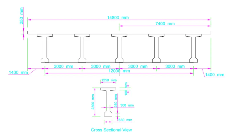
The general arrangement of superstructure is shown in the Figure 1. Five longitudinal girders are proposed with 3.0m C/C. These Each longitudinal girders are placed over POT-PTFE /Elastomeric bearings. The thickness of deck slab is considered 250 mm it. The total width of superstructure is 14.8. The cross girder/Diaphragm is provided at the support location.
Span 30 m bearing centre to centre: : 30 m
No of Span : 3 Nos
No of Each Span Girder : 5 Nos
Total No of Girder : 15 Nos
Report:
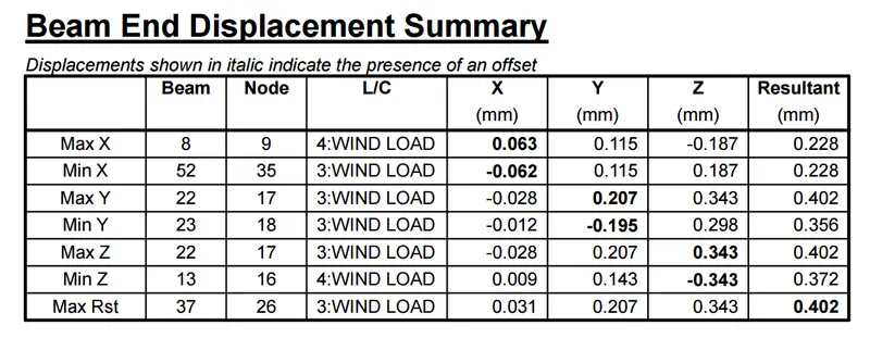
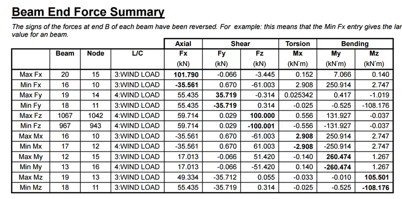
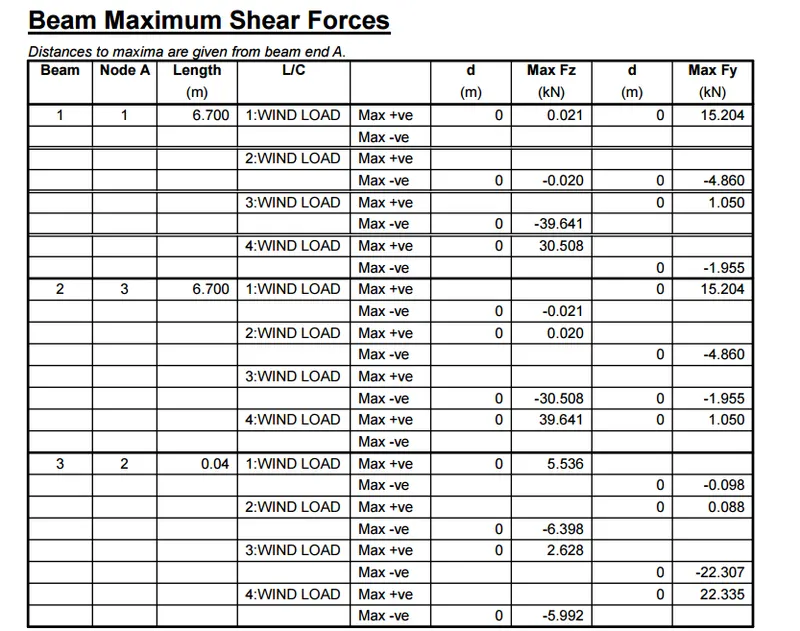
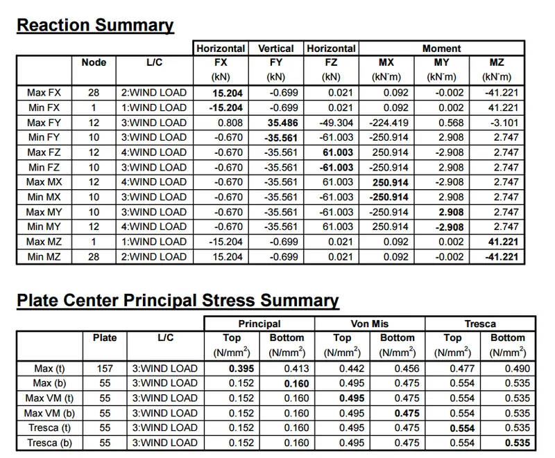
Beam End Force Summary: High to Low
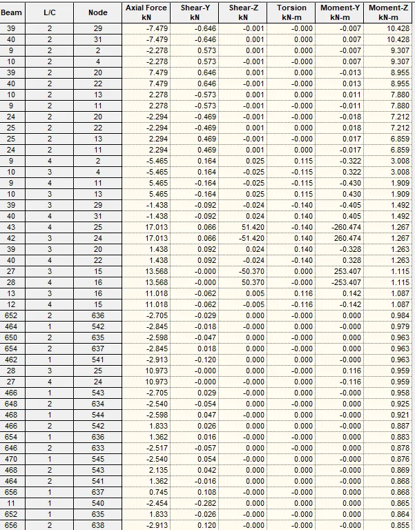
Outer Girder Maximum Bending Moment: