Week 3 Challenge
- Introduction:
Client Name (_______________________________________) has awarded Company Name ____________________________________ for Project Name(_____________________________________________________________________________________________________________________________________________________________________________________________________________________.
Company Name (______________________) has appointed INFRAENGG Design Agency’s name (__________________) as the “Design Consultant” to carry out the Detailed Design of the project corridor.
This Design note Pertains the design of RCC - I - Girder superstructures for IRS Loading
- Schedule of Spans & Dimensions:
The span and Girder arrangement details of the Structure: -
Detail of 25 m Span Superstructure:
| Solution: | Value | Unit | |
| Width of Deck Slab | : | 26.00 | m |
| Span of the Bridge | : | 25.00 | m |
| Pier height | : | 10.00 | m |
| Section of Girder | : | I | |
| Distance Centre to Centre of Girder | : | 3.50 | m |
| No of lane | : | 4.00 | m |
| Lane Width | : | 3.00 | m |
| · No of Girder | : | 8.00 | Nos |
| · Deck Thickness (Assumed) | : | 0.22 | m |
| · Crash barrier Bottom Width | : | 0.4 | m |
| · Railing Bottom Width | : | 0.30 | m |
| · Width of Shoulder | : | 3.00 | m |
| · Width of Footpath | : | 1.50 | m |
| · Carriage way Start from Median Edge | : | 1.80 | m |
| · 1st lane CW | : | 6.00 | m |
| · I Girder Details | : | ||
| § Height of Girder | : | 1.60 | m |
| § Top Flange Thickness | : | 0.18 | m |
| § Thickness of Web | : | 0.30 | m |
| § Width of Bottom Flange | : | 0.85 | m |
| § Thickness of btm Flange | : | 0.25 |
m |
| · Loading on the Structure | : | ||
| IRS Loading | : | ||
| 1. Metro Rail Loading | : | Load in Kn | Distance(M) |
| : | 170.00 | 2.1 | |
| : | 170.00 | 2.2 | |
| : | 170.00 | 12.4 | |
| : | 170.00 | 2.2 | |
| : | 170.00 | 2.1 | |
| 2. Electric Train Loading | : | ||
| : | 74.50 | 0.914 | |
| : | 74.50 | 0.914 | |
| : | 74.50 | 2.743 | |
| : | 74.50 | 0.914 | |
| : | 74.50 | 0.914 | |
| 3. Broad gauge Train Loading | : | ||
| : | 118.40 | 1.6 | |
| : | 187.00 | 2.794 | |
| : | 190.50 | 1.689 | |
| : | 192.40 | 1.689 | |
| : | 192.50 | 1.829 | |
| : | 178.40 | 3.048 | |
| : | 187.00 | 2.972 | |
| : | 187.00 | 2.134 | |
| : | 188.75 | 2.438 | |
| : | 187.85 | 2.134 | |
| : | - | 1.397 | |
| Load Details: | : | ||
| · Footway Loading (Assumed) | : | 5.00 | Kn/m |
| · Crash Barrier Loading (Assumed) | : | 7.50 | Kn/m |
| · Self- Weight of The Structure | : |
- General Arrangement:
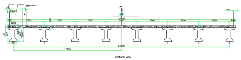
The general arrangement of superstructure is shown in the Figure 1. Five longitudinal girders are proposed with 3.0m C/C. These Each longitudinal girders are placed over POT-PTFE /Elastomeric bearings. The thickness of deck slab is considered 220mm it. The total width of superstructure is 26.0m. The cross girder/Diaphragm is provided at the support location.
Electric Train Load:
Load Sequence:-
| 74.50 | |
| 74.50 | 0.914 |
| 74.50 | 0.914 |
| 74.50 | 2.743 |
| 74.50 | 0.914 |
| 74.50 | 0.914 |
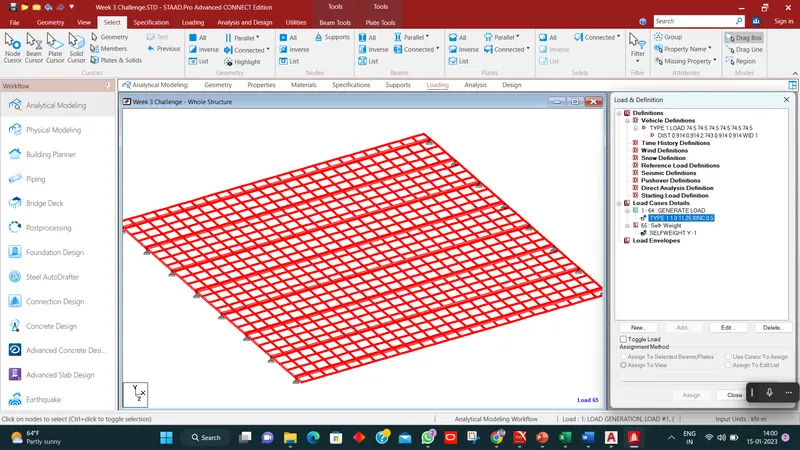
No of loads to be generated= ({Travelling Distance + Train Length)/ Load Increment Value}+1=(25+6.399)/.5+1=64 Nos
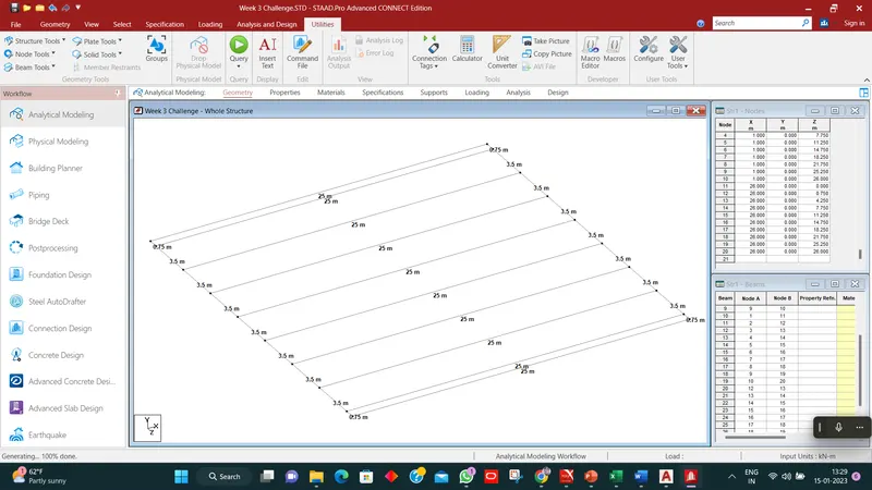
Geo-metry Figure of the structure
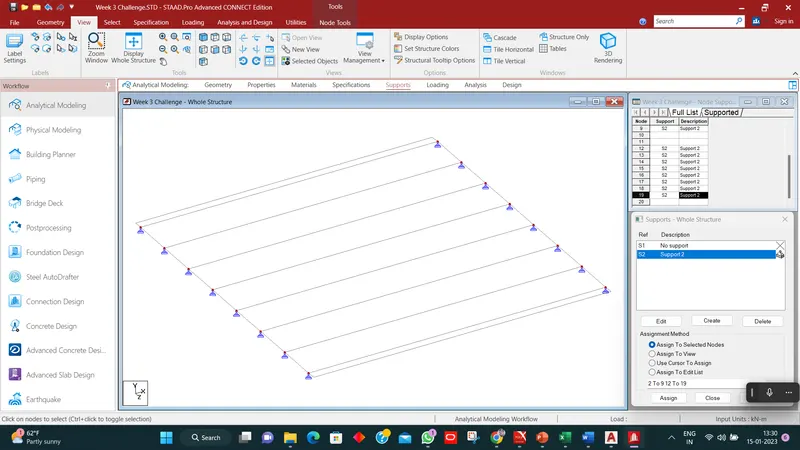
2. Support Assigned :
3.Properties Assigned the following members:-
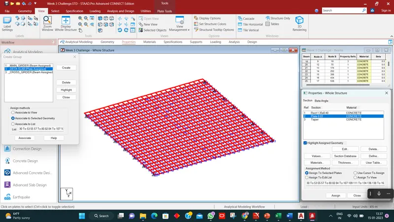
4.3D View after assinged the properties:-
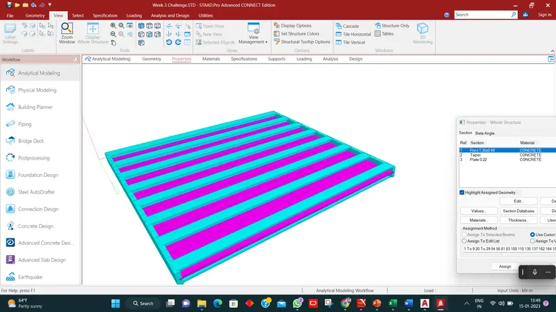 6. Load Assigned on the structure:- Metro-Rail loading
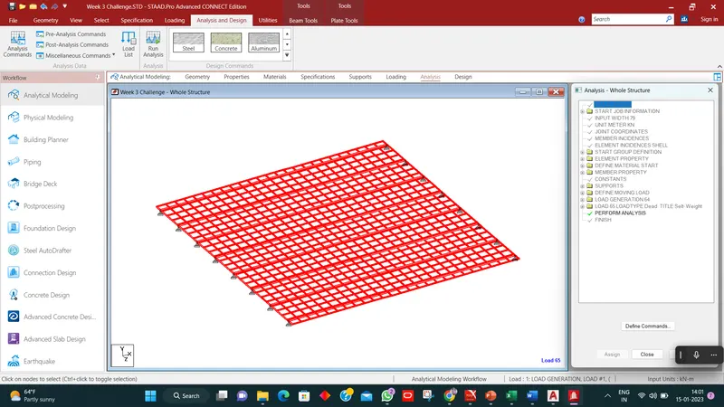
7.Perform Analysis:
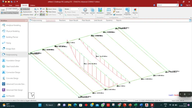
8.maximum bending Moment at mid Span:-
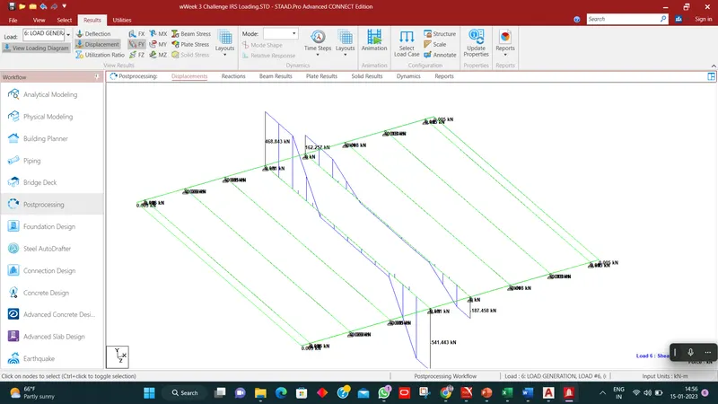
9.Max. Shear Force at End
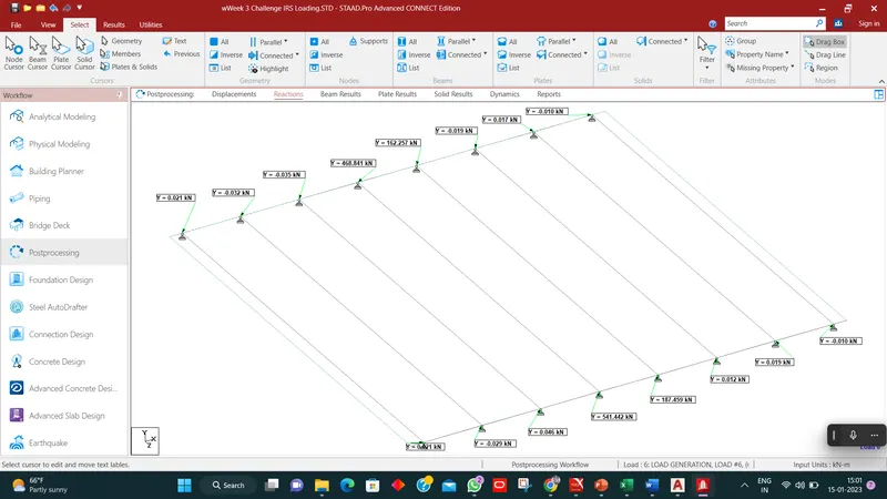
10. reaction at Y direction:
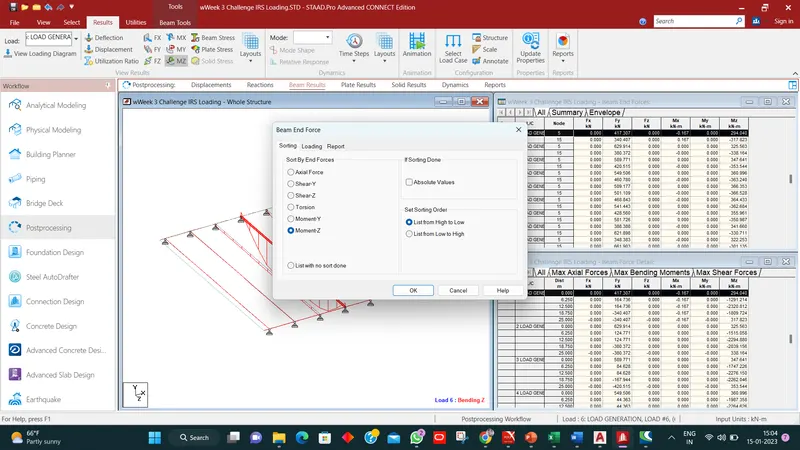
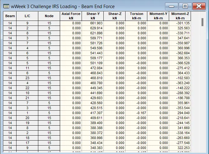
11. beam End Force acoording to high to low sequence:-
12.
Electric train Loading:-
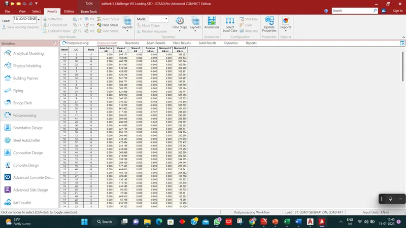
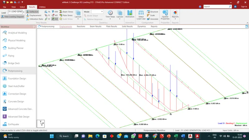
Report :-
| Output Results after Analysis of the Model | |||||||||
| Apply IRS Metro-Rail and Electric Train Load | |||||||||
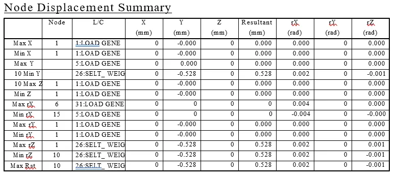
| Node Displacement Summary | |||||||||
| Max./Min. | Node | L/C | X (mm) |
Y (mm) |
Y (mm) |
Resultant (mm) |
rX (rad) |
rY (rad) |
rZ (rad) |
| Max X | |||||||||
| Min X | |||||||||
| Max Y | |||||||||
| Min Y | 10 | 26 self-weight | -0.528 | ||||||
| Max Z | |||||||||
| Min Z | |||||||||
| Max rX | |||||||||
| Min rX | |||||||||
| Max rY | |||||||||
| Min rY | |||||||||
| Max rZ 1 | |||||||||
| Min rZ | |||||||||
| Max Rst | 10 | 26 self-weight | 0.528 | ||||||
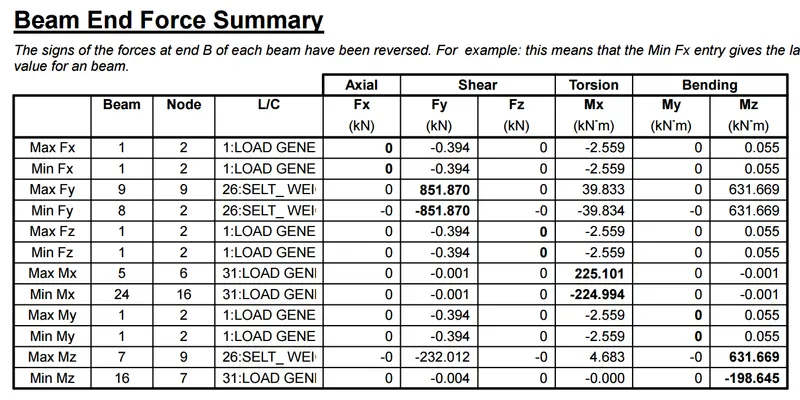
| Beam End Force Summary | |||||||||
| Max./Min. | Beam | Node | L/C | Axial | Shear | Torsion | Bending | ||
| Fx (kN) |
Fy (kN) |
Fz (kN) |
Mx (kN-m) |
My (kN-m) |
Mz (kN-m) |
||||
| Max FX | |||||||||
| Min FX | |||||||||
| Max FY | 9 | 9 | 26 self-weight | 851.87 | |||||
| Min FY | 8 | 2 | 26 self-weight | -851.87 | |||||
| Max FZ | |||||||||
| Min FZ | |||||||||
| Max MX | |||||||||
| Min MX | |||||||||
| Max MY | |||||||||
| Min MY | |||||||||
| Max MZ | 7 | 9 | 26 Self Weight | 631.669 | |||||
| Min MZ | 16 | 7 | 31 load Generation | -198.645 | |||||
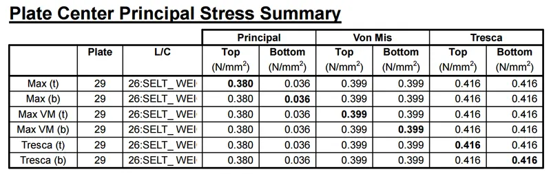
| Plate Center Principal Stress Summary | |||||||||
| Max./Min. | Beam | Plate | L/C | Principal | Von.Mis | Tresca | |||
| Top (N/mm2) |
Bottom (N/mm2) |
Top (N/mm2) |
Bottom (N/mm2) |
Top (N/mm2) |
Bottom (N/mm2) |
||||
| Max(Top) | 29 | 26 Self Weight | 0.38 | 0.036 | |||||
| Max(Bottom) | 29 | 26 Self Weight | |||||||
| Max. VM(Top) | |||||||||
| Max. VM(Bottom) | |||||||||
| Tresca(Top) | |||||||||
| Tresca(Bottom) | |||||||||
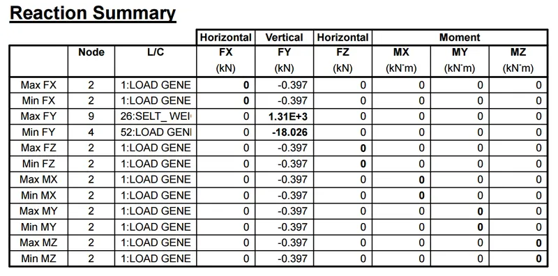
| Reaction Summary | |||||||||
| Max./Min. | Beam | Node | L/C | Horizental | Vertical | Horizental | Moment | ||
| FX (KN) |
Fy (KN) |
Fz (KN) |
FX (KN-m) |
Fy (KN-m) |
Fz (KN-m) |
||||
| Max FX | |||||||||
| Min FX | |||||||||
| Max FY | 9 | 26 self-weigth | 6.560842 | ||||||
| Min FY | 51 load generation | -18.026 | |||||||
| Max FZ | |||||||||
| Min FZ | |||||||||
| Max MX | |||||||||
| Min MX | |||||||||
| Max MY | |||||||||
| Min MY | |||||||||
| Max MZ | |||||||||
| Min MZ | |||||||||
Report Summary(after analysis):-