Week 5 Bending of iPhone
Aim
a) To simulate the bending of given iPhone model
b) To obtain the results as per the requirements in the question
c) To compare the results of the cases mentioned in the video
Procedure
1. Imparting the model
1.1 Original Geometry
After opening the ANSYS Workbench and selecting the static structural analysis, first of all the model has been imparted and edited in spaceclaim as given below:
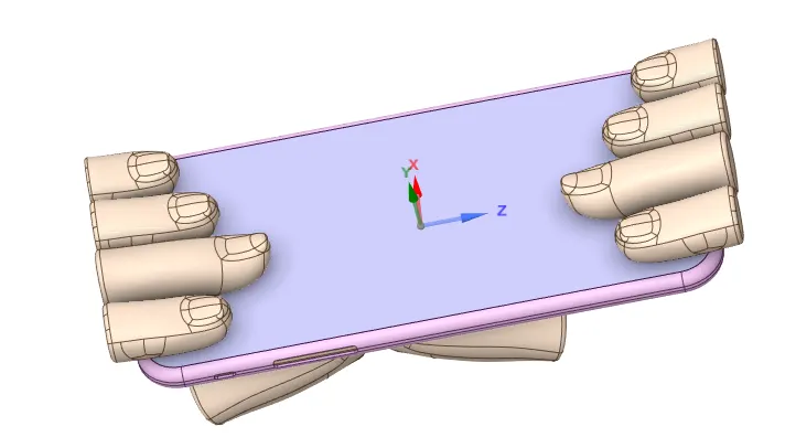
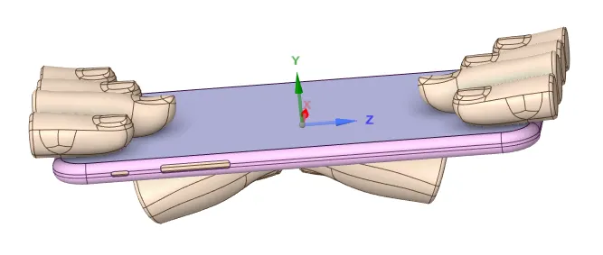
1.2 Modified Geometry (x=22.5 and Z=10)
Using the surfaces merge option, feometry has been edited in spaceclaim. The modified geomtery is shown as below:
2. Material Data
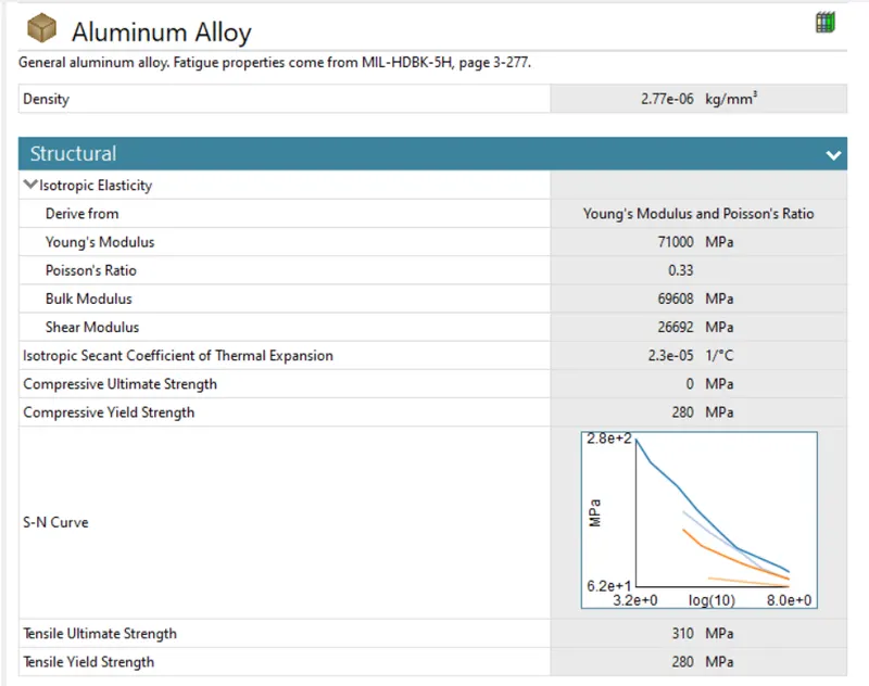
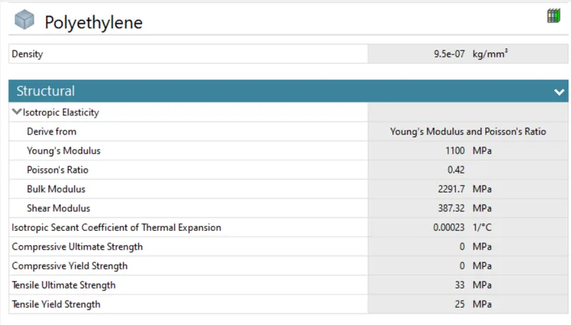
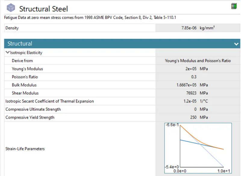
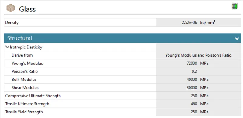
For frame of given iPhone, Aluminum alloy has been selected and for display glass has been selected. For interior part polyethylene has been assigned and for pushing fingers and other fingers, structural steel has been assigned.
The material properties are as follows:
3. Connections
3.1 contacts
3.1.1 Frictionless Contacts
There are many frictionless contacts defined in this simulation and the details are given below:
Between Display and Interior
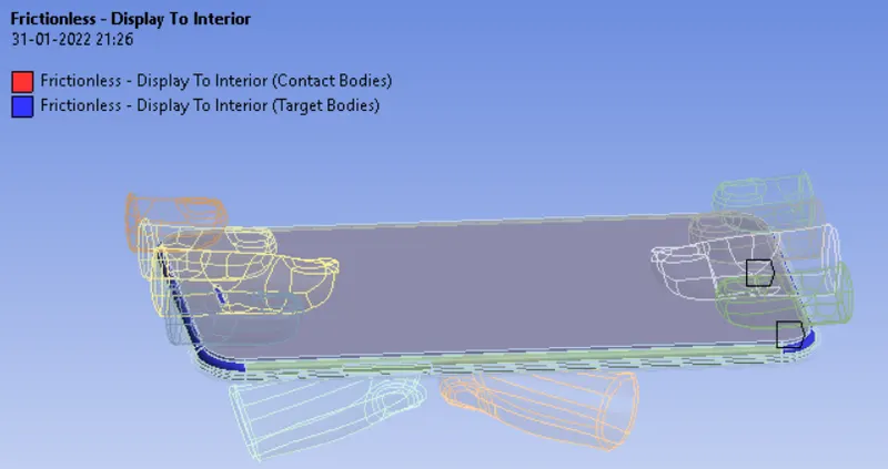
As shown above, frictionless contact has been assigned between display and interior.
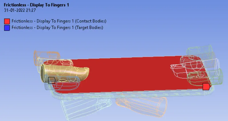
As shown in the above figure, all the fingers of the top surface of display has been assigned the frictionledd contact between display and fingers.
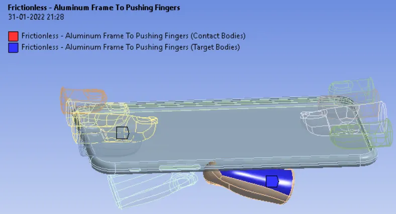
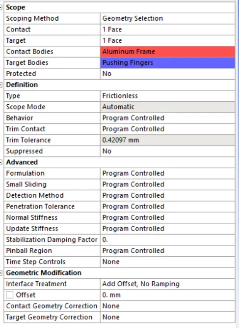
As shown above, the frictionless contacts have also been assigned to the pushing fingers and frame.
3.1.2 Bonded Contact
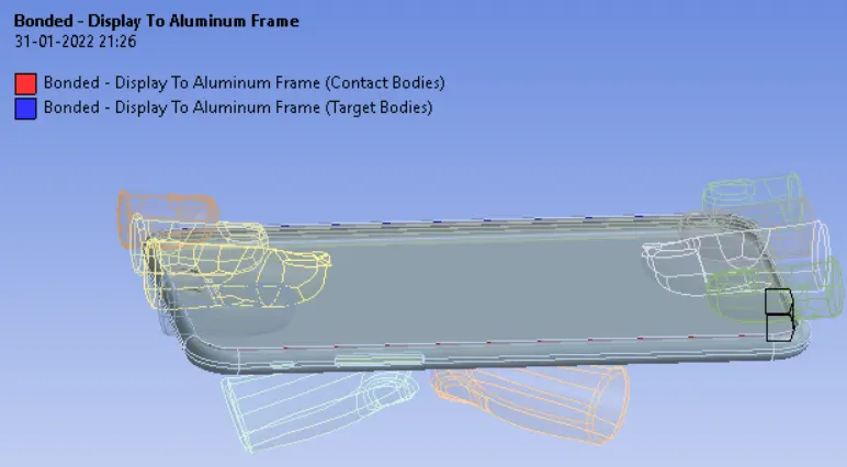
There was only one bonded contact that was assigned to Aluminum frame and display.
3.2 Joints
3.2.1 Fixed Joints
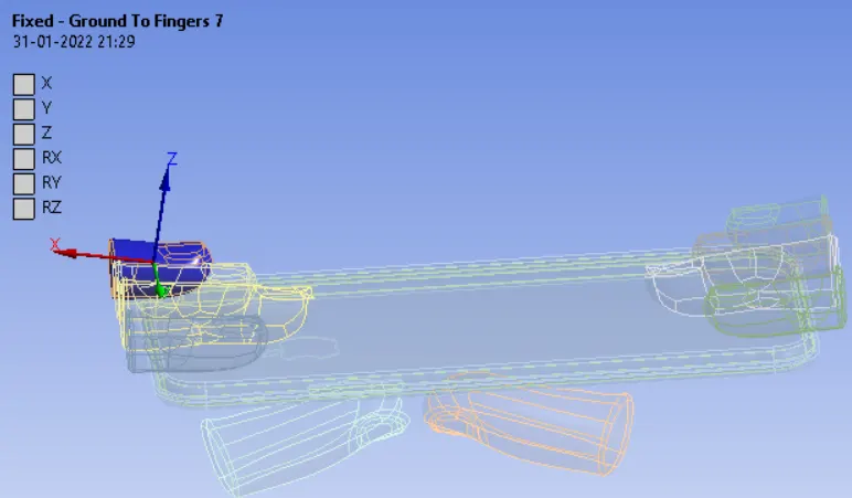
Just like above, all the top surface fingers have been assigned as fixed joint from body to ground.
3.2.2 Translatory Joint
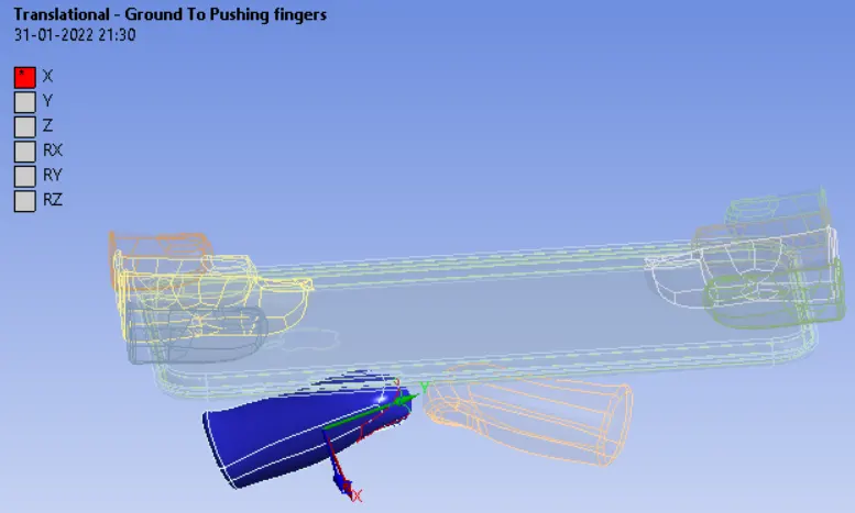
For both of the pushing fingers, translatory joint has been assigned and these joints were translated in the X Direction.
4. Mesh Details
Face Sizing
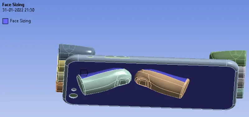
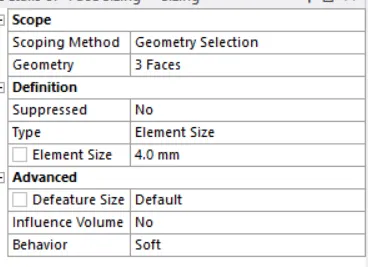
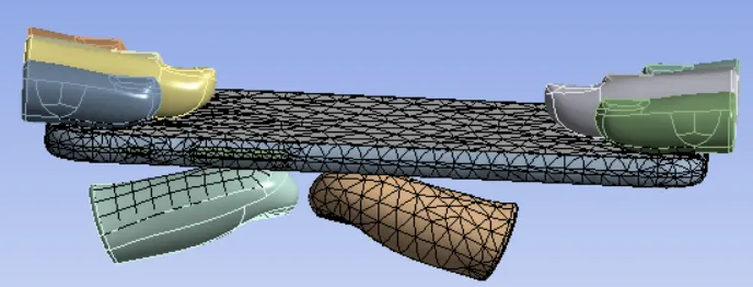
As shown above, the selected faces have been assigned a finer mes of 4.0 mm size and for rest of the parts the mesh details were set as default. The mesh was looked as giben below:
5. Analysis Settings
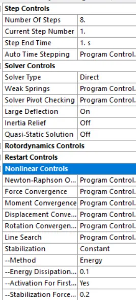
The anslysis was done in the eight steps with auto time stepping as program controlled and the stabilization method was fixed as constant. Energy dissipation ratio was given the value of 0.1. Weak springs were taken as program controlled.
6. Load Details
6.1 Fixed Support
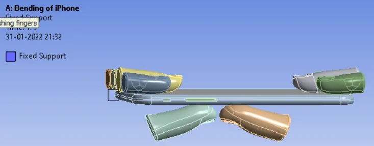
As shown above the two side surface of aluminum frame was assigned as foxed support so that the given model will not be translated in the upward direction completely.
6.2 Displacement
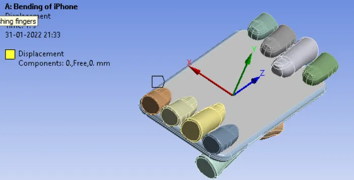
As shown above, the two side faces were give the zero displacement in the X and Z direction.
6.3 Joint Load
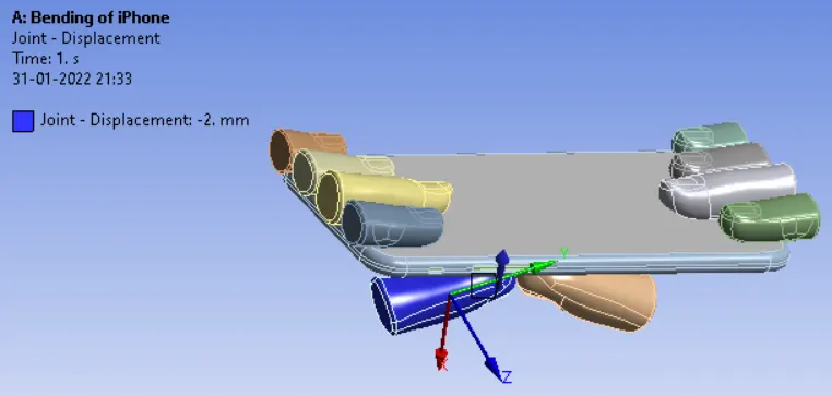
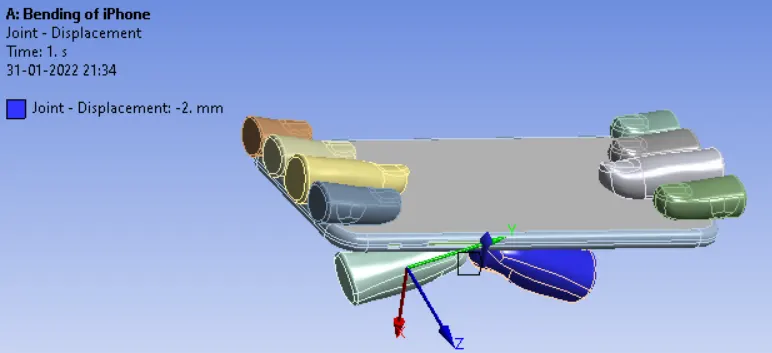
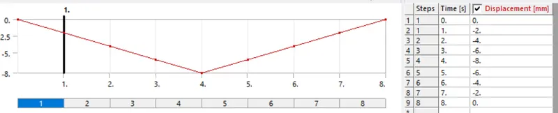
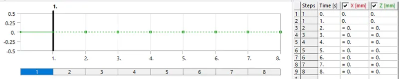
As shown in the above figure, the translatory joints were given the displacement in negative X direction.
7. Results
7.1 Case 1 - Original Position
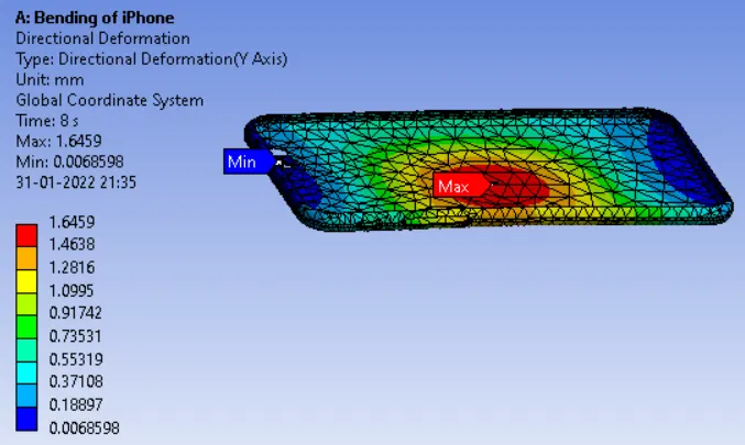
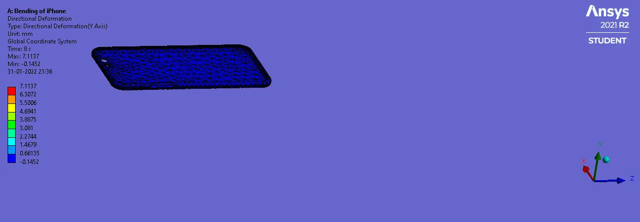
7.1.1 Directional Deformation (Y Axis)
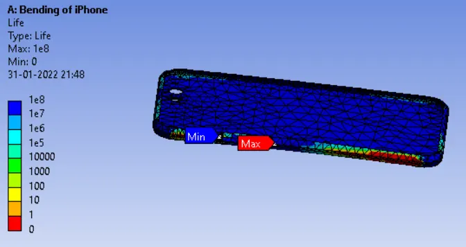
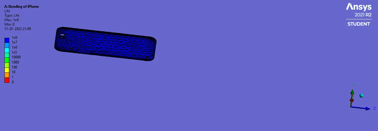
7.1.2 Fatigue Life
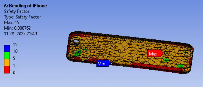
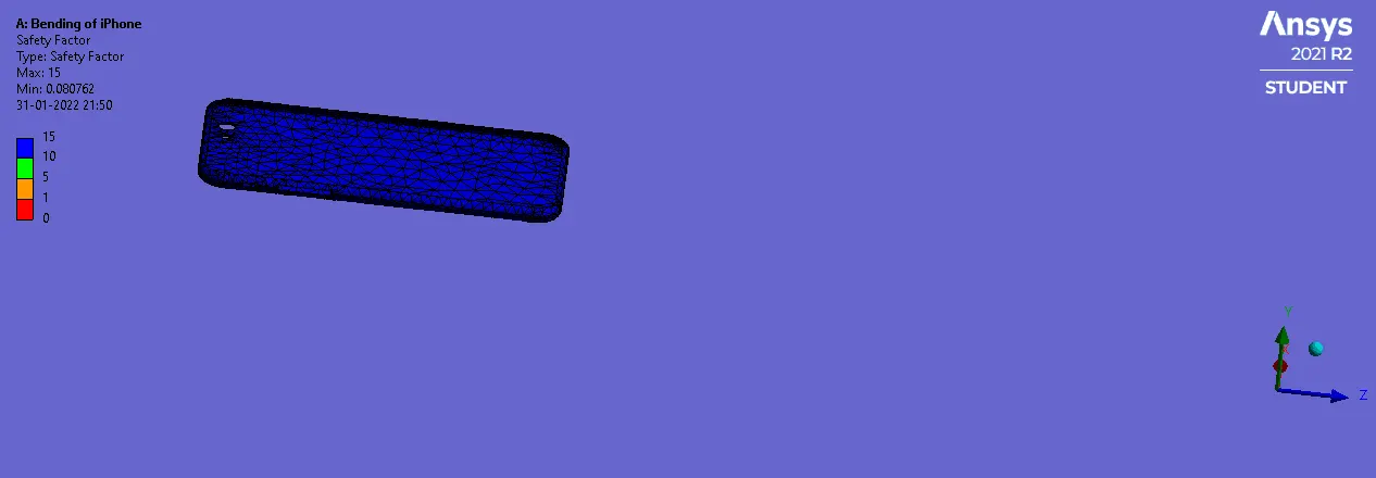
7.1.3 Fatigue Safety Factor
7.2 Case 2 - shifted Geometry (X=22.5 and Z=10)
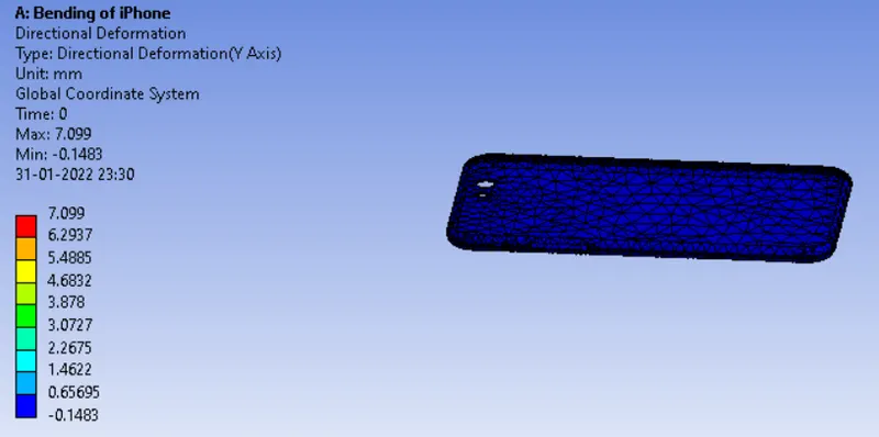
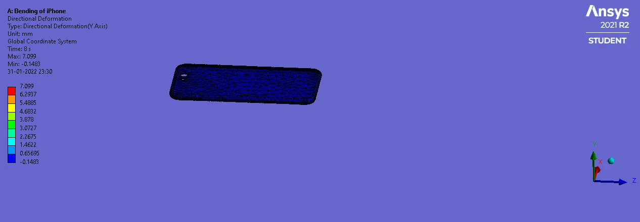
7.2.1 Directional Deformation
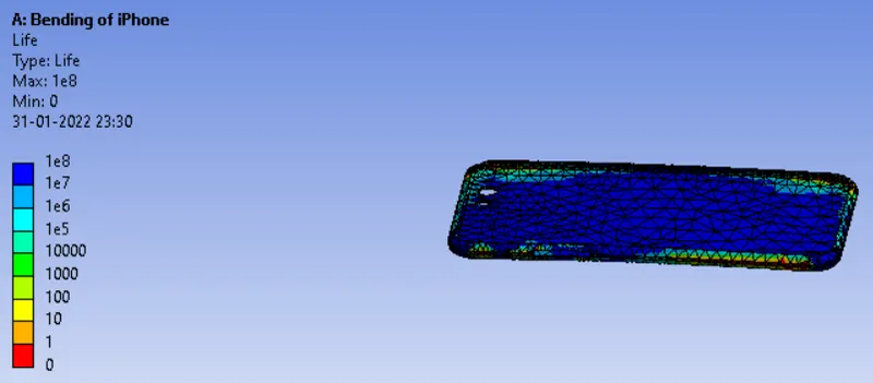
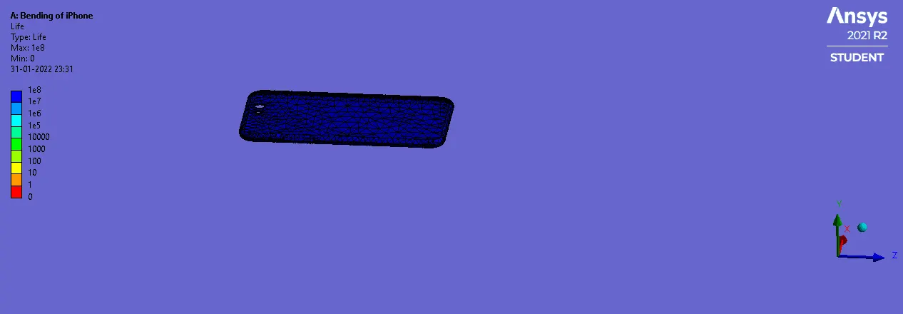
7.2.2 Life
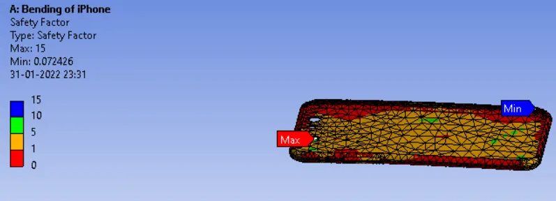
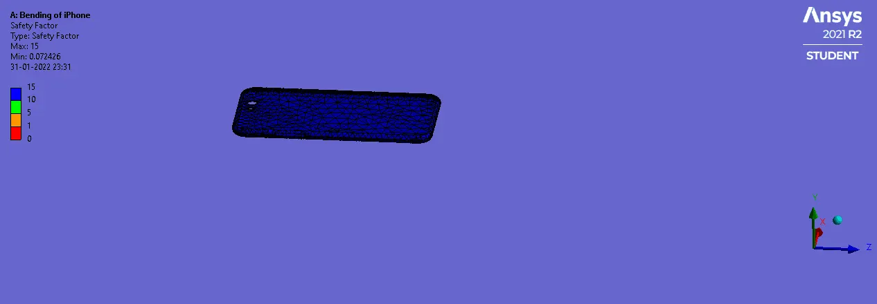
7.2.3 Fatigue Safety Factor
8. Conclusions
a) As seen in the above results, directional deformation is greater in case 1 as the geometry has been moved to somewhat near to the center.
b) Life if just the same for both the cases.
c) The fatigue load safety factor is also same for both the cases.