Week 5 Bending of iPhone
Aim:
For this challenge, simulate the bending of iPhone as per the given cases below
Case 1: Simulate the model as it is given in the video
Case 2: Move the bottom fingers from their defined position to the given position X= 22.5mm & Z= 10mm and obtain the results for the simulation. Also define the S-N curve for the Aluminium Alloy material as per values given below and determine the fatigue life results for the same.
| Stress, MPa | Number of Cycles, N |
| 225 | 10000 |
| 175 | 100000 |
| 143 | 1000000 |
| 110 | 10000000 |
| 80 | 100000000 |
Results and Deliverables
- Obtain the directional deformation for the model
- Factor of Aluminium Alloy NL
- Life of the Aluminium alloy for the case
- Compare the results and present with the conclusion.
Procedure:
Assign material as Glass for Display, Polyethelene for inner components and Magnesium Alloy ( Non Linear) from General non material list of materials. Now add a static structural simulation and change material of wire as Copper Alloy (Non Linear) for case 1.
Open the model in space claim module to check for any abnormalities in the model.
Connections :
Automatic connections are assigned by Ansys, among them assign Display to Casing as bonded connection else other connections as frictionless.
Assign all the top 8 fingers as fixed joint as they are acting as support for the model.
Assign the bottom 2 fingers as translation as they are applying the load on the model and displacing till 8 mm vertically.
Meshing:
The bottom 2 fingers and casing surface is assigned with 6mm mesh element size and other surfaces are assigned as default.
Analysis:
In the analysis screen do 8 steps analysis. With 1st step as Large defelection and stabilization on.
Fix the inner body by selecting two edge faces and assign the casing with displacement joint.
One by one assign both the lower fingers as displacment joints with tabular data upto 8 mm displacement in Y direction.
Now run the simulation and results are summarized below:
Results :
Case 1 :
Directional Deformation in the frame :
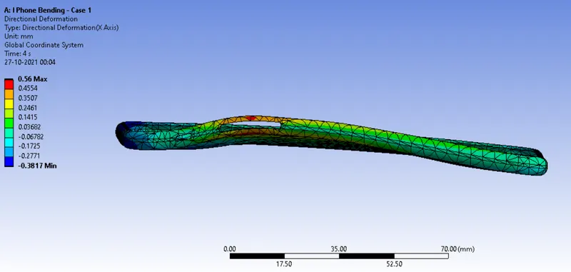
Factor of Safety for the frame :
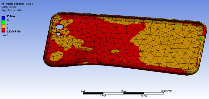
Life of frame :
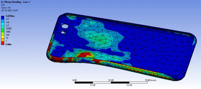
Case 2 :
Directional Deformation in the frame :
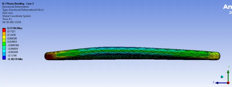
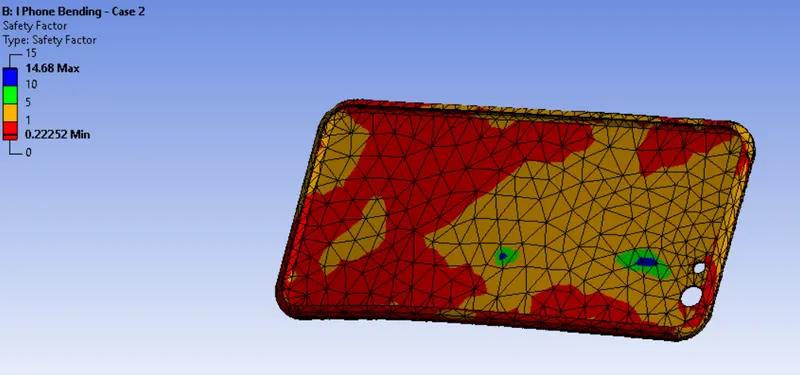
Factor of Safety for the frame :
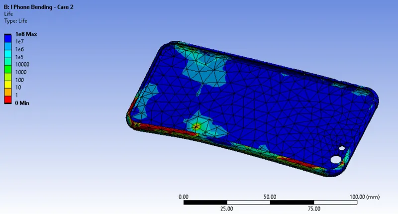
Life:
| Case | Max. Directional Deformation (Y-axis) | Factor of Safety |
Life of Case |
| 1 | 0.56 mm | 0.13 Min - 15 Max | 1 x e8 cycles |
| 2 | 0.21 mm | 0.22 Min - 15 Max | 1 X e8 cycles |
Conclusion :
Maximum deformation is in Case 1 as the force applied is near the border and load doesn't got distributed evenly.
Max Life is indicated with blue zones and least life through red zone.
Max Factor safety is indicated on Blue zone least on red zone.