Week 5 Bending of iPhone
OBJECTIVE
To simulate the bending of the iPhone for the following case study,
- Case (1): To simulate the model with bottom fingers in their pre-defined position.
- Case (2): To move the bottom fingers from their defined position to the given position X= 22.5mm & Z= 10mm and obtain the results for the simulation.
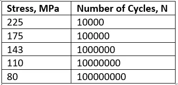
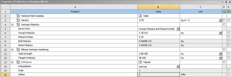
To define the S-N curve for the Aluminium Alloy material for the frame as per values given below and determine the fatigue life results for the same.
1. STEPS FOR PERFORMING ANALYSIS:
1. Open ANSYS workbench.
2. Select the static structural module.
3. Select the proper Engineering data card.
4. Import geometry.
5. Open Mechanical model.
6. Give proper connections (contacts and joints).
7. Generate mesh.
8. Set Analysis Setting as given.
9. Insert output request
10. Analyze Result.
2. ANALYSIS SETUP:
2.1 Geometry:
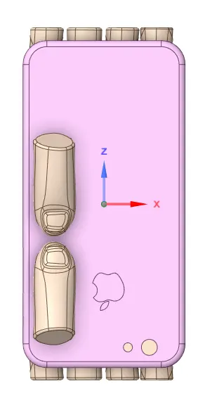
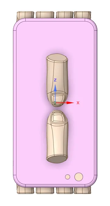
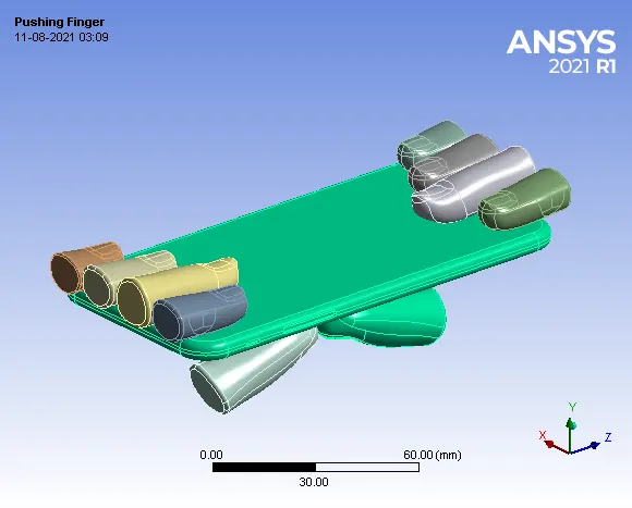
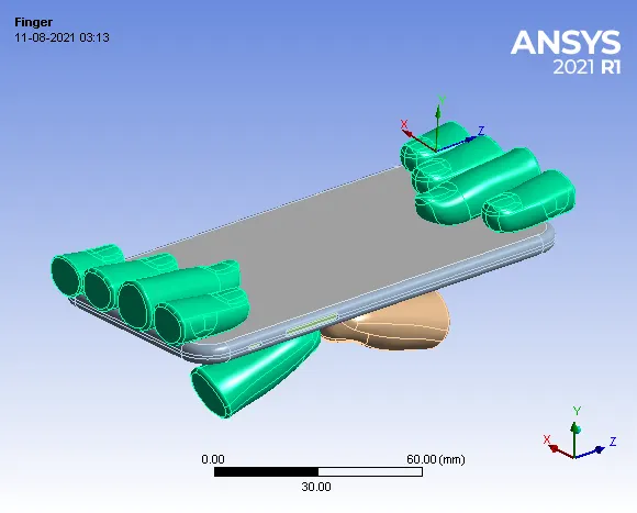
(a)Case 1: Initial position of pushing fingers. (b)Case 2: Pushing fingers moved to a defined position.
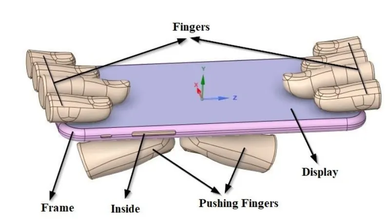
The given 3D model of iPhone bending assembly is imported into SpaceClaim. The iPhone assembly consists of a display, frame, inside parts, pushing fingers and supporting fingers. For case (1), the position of pushing fingers is as shown in fig. 2.1.1 (a). For case (2), the pushing fingers are moved from their defined position to the given position X= 22.5mm & Z= 10mm using the move option in SpaceClaim.
- Stiffness Behaviour
(c) Flexible Behaviour
(d) Rigid Behaviour
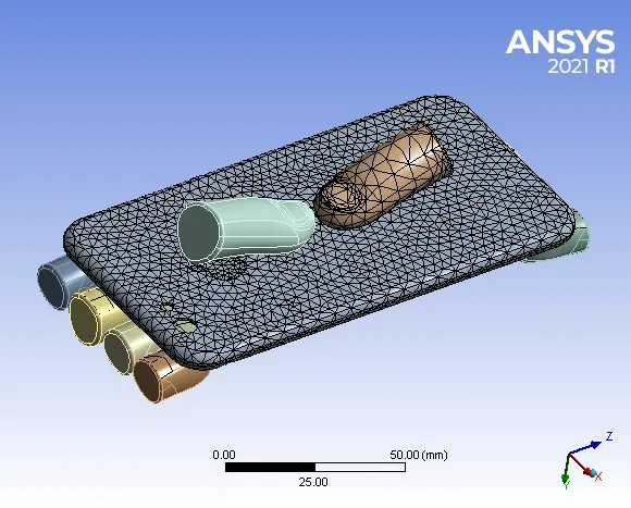
2.2 Meshed Model:
- Details:
- Face Sizing: Bottom surafce of Frame = 3 mm
- Global Sizing = 6 mm
- No of Nodes = 30556
- No of Elements = 12770
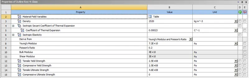
2.3 Material Properties:
- For Display: Glass
- For Frame: Aluminium Alloy NL.
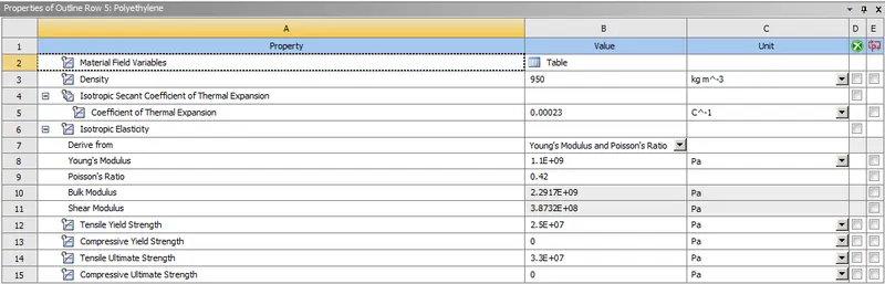
- For Inside: Polyethylene
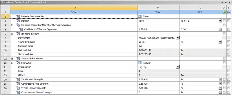
- For Fingers: Structural Steel.
2.4 PROCEDURE:
(2.4.1) Import model in ANSYS Workbench.
(2.4.2) Assign material properties.
(2.4.3) Open the mechanical module, where we going to perform analysis.
(2.4.4) Meshed the model with desired element size.
(2.4.5) Now after meshing, From Project Tree, select "Connections" and create "Contacts"
- CONTACTS
1.Bonded: Display to Frame
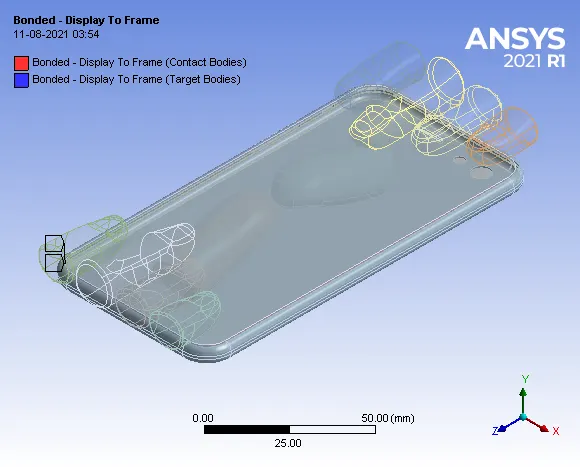
2. Frictionless Contact: Display and fingers assigned as frictionless.
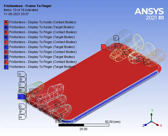
(2.4.6) Joint Details.
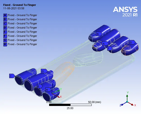
1. Fixed Joint: The fixed joint is assigned to all supporting fingers.
2. Translational Joint: Applied to pushing fingers.
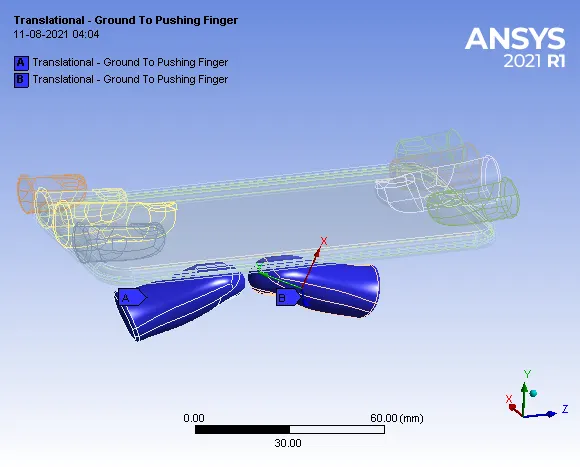
The fixed type of joint is assigned for supporting fingers to hold the display with the connection type being body-ground. The translational type of joint is assigned for both pushing fingers with the connection type being body-ground since the pushing fingers have to move upward to bend the iPhone.
(2.4.6) Analysis Setting:
- Now let's define the Analysis Setting.
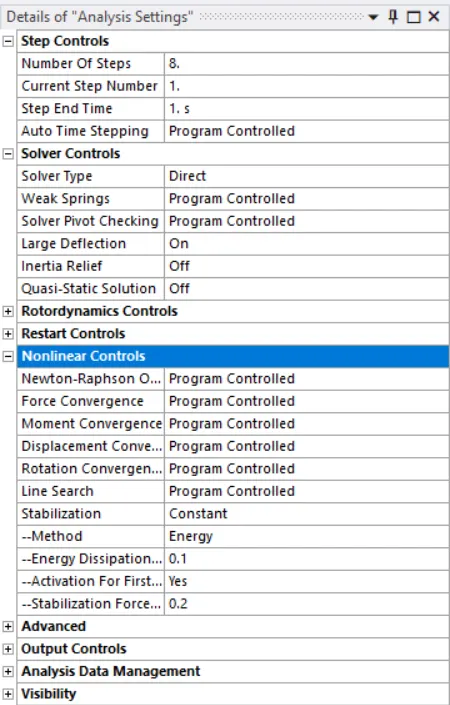
In the analysis settings, the number of steps considered is 8. In solver controls, the solver type selected is ‘Direct’, with weak spring set as ‘Program controlled’ and large deflection is set to ‘On’. Under the nonlinear controls, the stabilization is set as constant with the energy dissipation ratio being ‘0.1’ and activation for the first sub-step set as ‘Yes’.
(2.4.7) BOUNDARY CONDITIONS:
- Now let's define the Boundary Condition
1. Fixed Support: Fixed support to the surface of the inside of the i-phone.
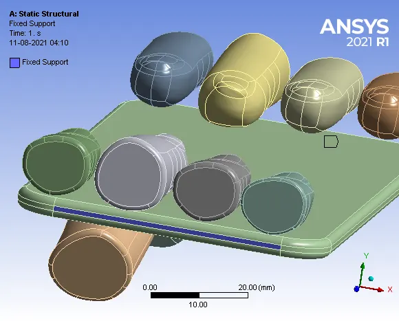
Fig. (a) Fixed Support.
2. Displacement: Displacement applied on the frame along Y-axis, X and Z axis should be constant.
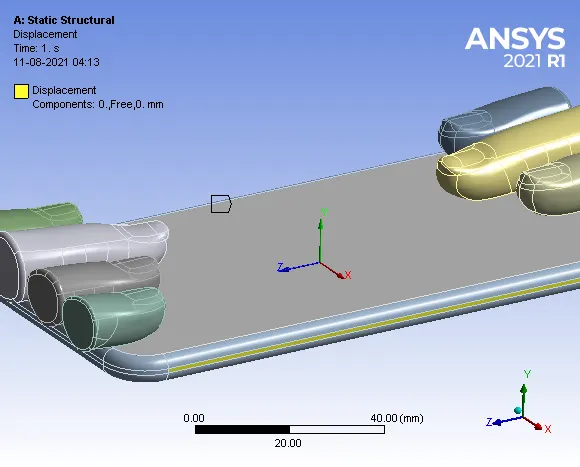
Fig. (b) Displacement
3. Translational Joint Load:
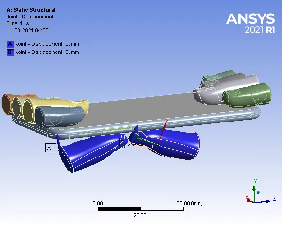
Fig. (C) joint Load
The fixed support is applied on the surface of the inside part of the iPhone on both sides. To move the iPhone in upward Y-direction while pushing, the displacement is set to free in Y-direction and constrained in another direction. To bend the iPhone, the translational joint load is applied on both pushing fingers as shown in fig (C).
(2.4.7) SOLUTION:
- After giving proper Boundary conditions, create a solution for the output result.
- Obtain the directional deformation for the model
- The factor of Aluminium Alloy NL
- Life of the Aluminium alloy for the case
3. RESULT AND DISCUSSIONS:
(A) CASE 1: Bottom fingers in their pre-defined position.
1. Directional Deformation:
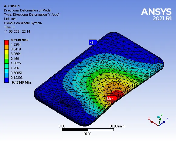
Maximum deformation = 4.8149 mm
- Deformation Contours:
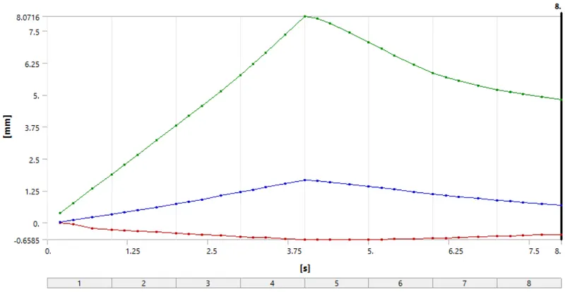
The maximum deformation of the Model along the Y-axis reaches a maximum of 8.0716 mm at the lower side of the hole region for the side button and reduces as the load is removed and reaches a value of 4.8149 mm at the end of step 8. Hence, it is observed from the plot that the model deforms plastically and does not regain its original shape and position.
2. Directional Deformation of Frame:
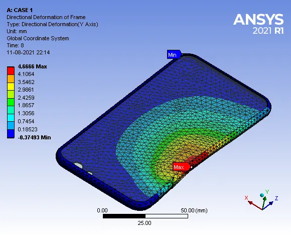
Maximum Deformation = 4.6666 mm
- Deformation Contours:
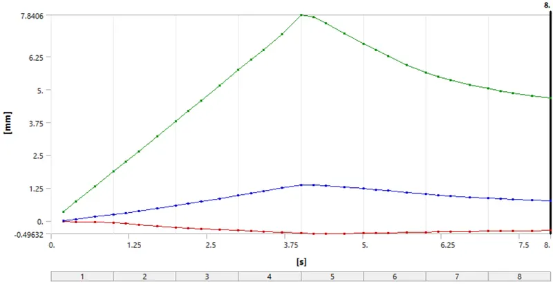
The maximum deformation of the frame along the Y-axis reaches a maximum of 7.8406 mm at the lower side of the hole region for the side button and reduces as the load is removed and reaches a value of 4.6666 mm at the end of step 8. Hence, it is observed from the plot that the frame deforms plastically and does not regain its original shape and position.
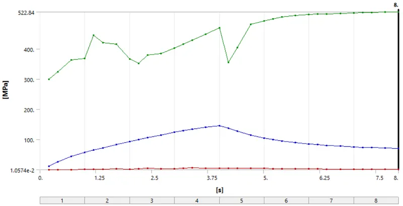
3. Equivalent v-m Stress:
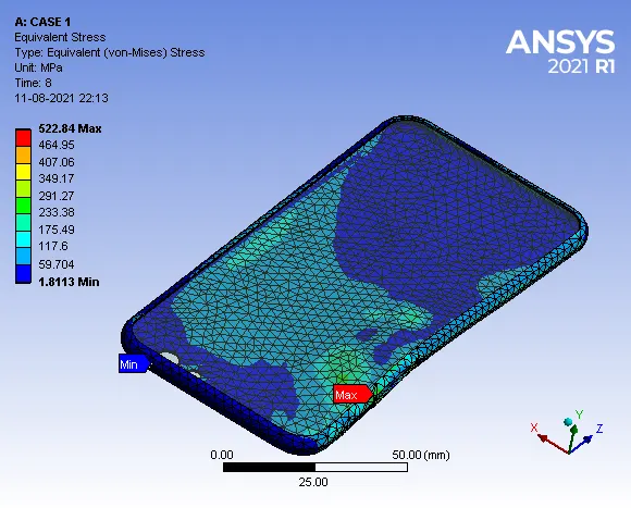
Maximum Stress = 522.84 MPa
- Stress Contours:
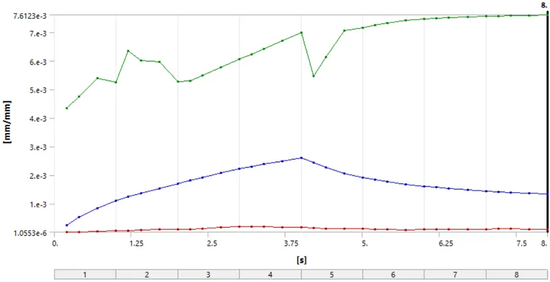
4. Equivalent Elastic Strain:
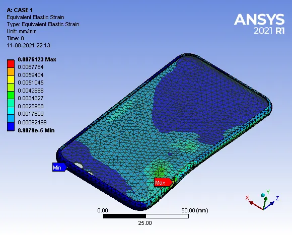
Maximum Strain = 0.0076123 mm/mm
- Strain Contours:
5. Fatigue Safety factor of Frame:
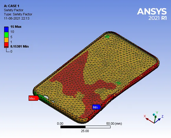
The fatigue safety factor for the aluminum alloy NL material of frame is 0.15301, which is less than 1, hence material cannot sustain the applied load and eventually leads to failure.
6. Fatigue Life of Frame:
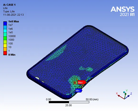
The maximum fatigue life of frame is 1e8 cycles. The minimum life of frame is 0 cycles which is observed near the region of side button hole, hence there is possibility of crack propagation and failure of the component.
(B) CASE 2: Bottom fingers moved from their defined position to the given position X= 22.5mm & Z= 10mm.
1. Directional Deformation of Model:
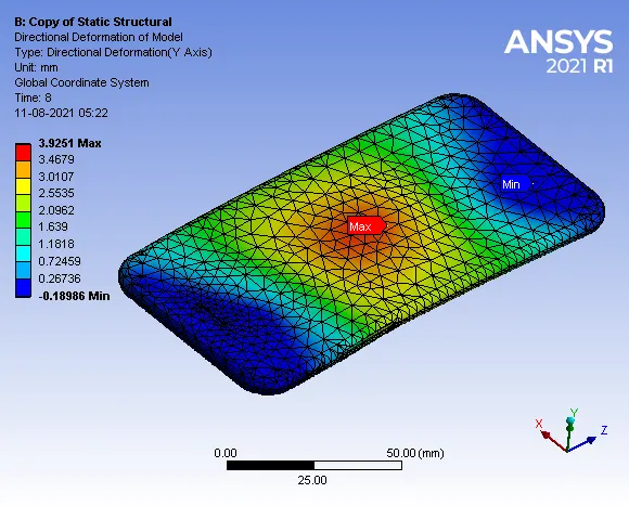
Maximum Deformation = 3.9251 mm
- Deformation Contours:
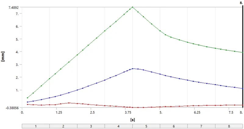
2. Directional Deformation of Frame:
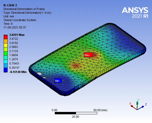
Maximum Deformation = 3.9251 mm
- Deformation Contours:
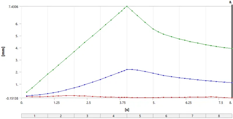
The maximum deformation of the frame along the Y-axis reaches a maximum of 7.4306 mm at the middle and reduces as the load is removed and reaches a value of 3.9251 mm at the end of step 8. Hence, it is observed from the plot that the frame deforms plastically and does not regain its original shape and position.
3. Equivalent v-m Stress:
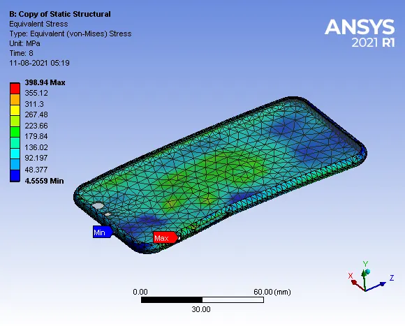
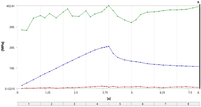
Maximum Stress = 398.94 MPa
The maximum v-m Stress developed in the frame is 398.94 MPa near the hole region for the side button.
- Stress Contours:
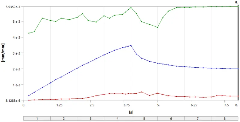
4. Equivalent Elastic Strain:
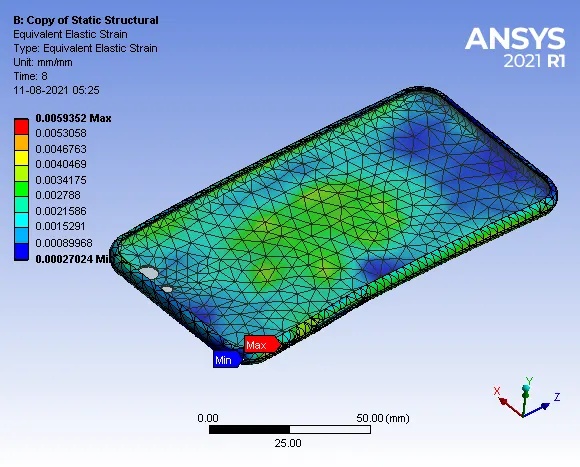
Maximum Strain = 0.0059352 mm/mm
The maximum Equivalent Elaastic strain developed in the frame is 0.0059352 near the hole region for the side button.
- Strain Contours:
5. Fatigue Safety factor of Frame:
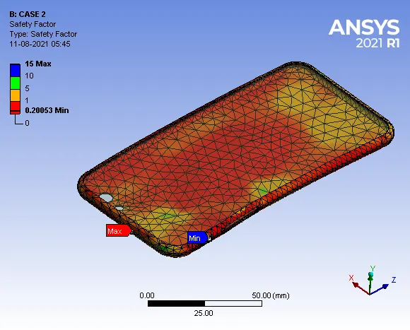
The fatigue safety factor for the Aluminium Alloy NL material of the frame is 0.20053, which is less than 1, hence the material cannot sustain the applied load and eventually leads to failure.
6. Fatigue Life of Frame:
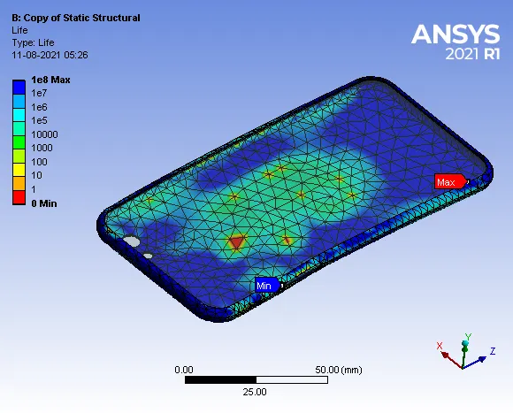
The maximum fatigue life of the frame is 1e8 cycles.
5. Comparison of Results:
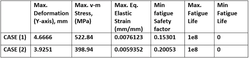
From the table, it is observed that the max. deformation along Y-axis, v-m stress and equivalent elastic strain for case (1) are more than compared to case (2) because the load applied through pushing fingers for case (2) is at the middle of the frame.
The minimum fatigue safety factor for Aluminium alloy NL material of frame in both cases is less than 1, hence the material cannot sustain the applied load and eventually leads to failure.
The minimum fatigue life of frame for case (2) is 0 cycles, hence there is the possibility of crack propagation and failure of the component.
The minimum fatigue life of frame for both cases is 0 cycles, hence there is the possibility of damage of the component.
6. CONCLUSION
1. Simulation of bending of iPhone was carried out successfully for the following case study,
- Case (1): Bottom fingers in their pre-defined position.
- Case (2): Bottom fingers moved from their defined position to the given position X= 22.5mm & Z= 10mm.
2. The values of max. deformation along Y-axis, v-m stress and equivalent elastic strain for case (1) are more compared to case (2) because the load applied through pushing fingers for case (2) is at the middle of the frame.
3. The minimum fatigue safety factor for Aluminium alloy NL material of frame in both cases is less than 1, hence the material cannot sustain the applied load and eventually leads to failure.
4. The minimum fatigue life of the frame for both cases is 0cycles, hence there is the possibility of damage of the component.