Week 5 Bending of iPhone
Objective:
The objective is to run the simultaion in 2 cases the first one being as shown in the video and the second one being by displacing the pushing fingers and giving an S-N curve for aluminium alloy as given above and to compare directional deformation, Factor o aluminium alloy and life of aluminium alloy.
Setup:
For the first case we insert the materials Aluminium alloy from general materials non-linear, then from general materials add polyethylene. Then duplicate polyethylene and change the properties to rename it to glass. For case 2 we need to add S-N curve to aluminium alloy and give the values for number of cycles as mentioned. Once that is done we import the geometry into spaceclaim to check for any abnormalities. If there is no abnormalities we load the model in mechanical module. Once loaded we name the parts as Glass, Internal, Frame, Pushing fingers and fingers reqpectively. All the fingers are assigned structural steel, Glass is assigned glass, Frame is assigned Aluminium Alloy and Internal is assigned polyethylene. All the fingers except one pushing finger is made rigid. Going into contacts we delete any finger to finger contacts. Then except the Glass to Frame contact which will be bonded all the other contacts are set as frictionless. Once that is done we select each finger hide all other bodies box select the finger and set it as geometry for ground to body fixed support except for the pushing fingers which will be translational Ground to body joint. For the pushing fingers make sure that the x axis is pointed up towards the phone. After defining all the joints we give a face sizign of 8mm to the contact surfaces between pushing finger and the phone back surface. We also give a patch conforming method of tetrahedrons for the Internal. Moving onto Analysis settings we give 8 steps chaneg solver type to direct, weak springs to program controlled, large deflection to on and all output controls to yes. We also make stabilization constant by giving a value of 0.1 switching activation for first step to yes. We the give a fixed support by selecting the edge surface on both sides of Internal, and a displacement in which X and Z are given the calues of 0 by selecting the sides of the frame. After that we give joint load to both the finger in y direction with 2.4.6.8.6.4.2 being the values. Then we select directional deformation along y axis as solution along with a fatigue tool which contains life and Safety Factor.
Case 1:
Total Deformation:
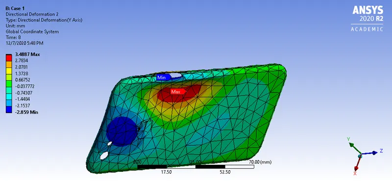
The maximum amount of deformation thats occured is at 3.4887mm at the point of application of the load.
For this case neither the life or the safety factor could be found out as there was no S-N curve for the selected material (Aluminium Alloy NL)
Case 2:
Directional Deformation:

The maximum deformation again occured at the point of application of pressure at 2.9584mm
Life:
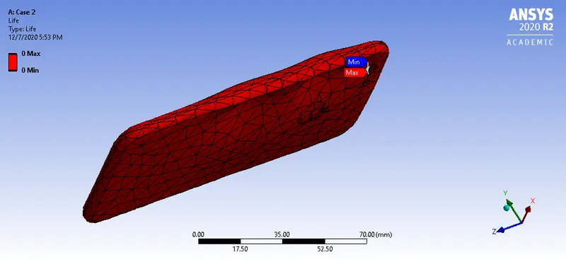
As expected the number of cycles the frame was able to withstand was at 0, as after the application of force the frame is bend.
Safety Factor:
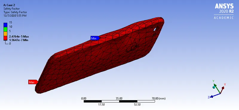
The safety factor obtained was at 15.
Conclusion:
Comparing the results we can see that the maximum amount of deformation occured at the point of application of the force for both models. with case 2 yielding less deformation than case 1. The stress developed in the first case was also higher when compared to the stress developed in the second case. In both cases the frame did bend but there was no crack. But the phone was bend in such a way that it wasnt recovering,i.e, it underwent plastic deformation.